Article

Single-Wire Electric-Field Coupling Power Transmission Using Nonlinear Parity-Time-Symmetric Model with Coupled-Mode Theory

School of Electric Power Engineering, South China University of Technology, Guangzhou 510641, China
*
Author to whom correspondence should be addressed.
Energies 2018, 11(3), 532; https://doi.org/10.3390/en11030532
Submission received: 20 January 2018 / Revised: 9 February 2018 / Accepted: 26 February 2018 / Published: 1 March 2018

Abstract

:
The output power and transmission efficiency of the traditional single-wire electric-field coupling power transmission (ECPT) system will drop sharply with the increase of the distance between transmitter and receiver, thus, in order to solve the above problem, in this paper, a new nonlinear parity-time (PT)-symmetric model for single-wire ECPT system based on coupled-mode theory (CMT) is proposed. The proposed model for single-wire ECPT system not only achieves constant output power but also obtains a high constant transmission efficiency against variable distance, and the steady-state characteristics of the single-wire ECPT system are analyzed. Based on the theoretical analysis and circuit simulation, it shows that the transmission efficiency with constant output power remains 60% over a transmission distance of approximately 34 m without the need for any tuning. Furthermore, the application of a nonlinear PT-symmetric circuit based on CMT enables robust electric power transfer to moving devices or vehicles.

1. Introduction

Since the discovery of electricity, the power transmission has mainly depended on the wires, and the way of power transmission through wires requires at least two wires to provide conduction paths for conduction current, which may be difficult to install but also has a large number of safety issues, such as the risk of fire and electric shock caused by short circuits. However, in the early 20th century, Nikola Tesla first proposed the concept of wireless power transmission (WPT) [1], which is a novel technology that can transfer power through air without wires. His imagination about global power transmission without wires also shocked the world. Although Tesla’s experiment was not completed due to funding problems [2], it caused numerous experts and scholars to start exploration and research on this technology which can provide human beings with more convenience of production and lifestyles.
Currently, WPT technology is mainly divided into three categories [3], namely, non-radiative WPT, radiative WPT, and electromechanical WPT. Among them, the most extensively studied are inductively coupling wireless power transmission (ICPT) [4], magnetic resonant coupling wireless power transmission (MRWPT) [5], microwave wireless power transmission (MWPT) [6], and laser wireless power transmission (LWPT) [7]. The concept of ICPT was first proposed by Professor J. T. Boys of the University of Auckland, New Zealand. His research team started to study this technology as early as the 1990s, and achieved a great deal of success [8,9,10]. In the theoretical analysis, a lot of studies have been done on the basic principle, characteristic analysis, compensation circuit analysis, frequency splitting and stability of ICPT [8,9,10]. In practical application, inductive wireless charging for electric vehicles, mobile robots, and implanted devices were studied [11,12,13]. Professor Marin of MIT (Massachusetts Institute of Technology) proposed a new MRWPT technology and published it in the magazine Science in 2007 [5]. Until now, great progress has been made in the modeling of the system, impedance matching, electromagnetic safety, and standard setting [14,15]; in the application, Haier developed the tailless television in 2010, the KAIST (Korea Advanced Institute of Science and Technology) established a 12-km demonstration route of dynamic power supply for electric vehicles in Gumi city, South Korea in 2015, and the company of Zhonghui Chuangzhi in China applied MRWPT technology to charge a mine equipment monitoring system. As early as 1964, Willian C. Brown of Raytheon succeeded in using the MWPT technology to power a helicopter platform [16]. Subsequently, many scientists continued to study this technology, however, the bottleneck of transmission efficiency higher than 10% cannot be broken through. The technology of LWPT is still in the experimental stage and has not been put into practical application, Japan started experimenting on LWPT in 1997 [17], and used laser energy to power robots, kites, and helicopters [7,18]; scientists from Germany and the United States conducted experiments about LWPT in succession [19,20]. The first two WPT technologies have more extensive application and development prospects since the transmission efficiency of the latter two kinds of WPT technology is very low and the sensitivity of the direction is extremely high. The transmission distance of inductively coupling WPT is relatively close, in the range of tens of centimeters, and the distance of magnetic resonant coupling WPT is relatively far, in the range of a few meters, while its output power is not high, only suitable for low-power applications, such as mobile phones and other portable devices [21]. In addition, the output power and transmission efficiency of these two WPT system both decrease rapidly with the increase of the transmission distance [22,23]. To overcome the danger of two-wire or three-wire power transmission modes and improve the transmission distance at the same time, a single-wire power transmission system was proposed [24]. Dmitry S. Strebkov of the All-Russia Institute of Agricultural Electrification produced single-wire power transmission systems of different voltage levels with a total capacity of 1 kW and high transmission efficiency in 2000 [25]. In 2011, Steve Jackson gave a presentation about single-wire power transmission at McMaster University in Canada, with a transmission distance of up to 20 m [26].
The single-wire power transmission system can transfer high energy to the load with only one wire, simultaneously the transmission distance can be up to tens of meters. Whereas keeping constant output power while maintaining high constant transmission efficiency against variable distance is also a significant challenge for single-wire ECPT systems.
Furthermore, the concept of PT-symmetry originated in the optical system, and was first applied to the related fields of WPT in 2017 [27]. A PT-symmetric system supports two phases, including an unbroken and broken phase, only the characteristics of unbroken phase were used in WPT system. In the unbroken phase, eigenfrequencies of the system remain real and the energy is equally stored in transmitting and receiving resonators [28]. Despite its many advantages, the nonlinear PT-symmetric model is not applied in actual WPT systems, especially the single-wire ECPT system.
In order to make the output power and efficiency of the single-wire ECPT system robust to the transmission distance, in this paper, a novel nonlinear PT-symmetric model based on CMT for single-wire ECPT system is proposed. Firstly, a theoretical model of single-wire ECPT system is established based on CMT, then, the PT-symmetric model of the system is obtained, and the transmission characteristics of the system is analyzed. Finally, the results by the analysis of circuit simulation show that the transmission efficiency with constant output power remains near 60% within the critical distance of 34 m.

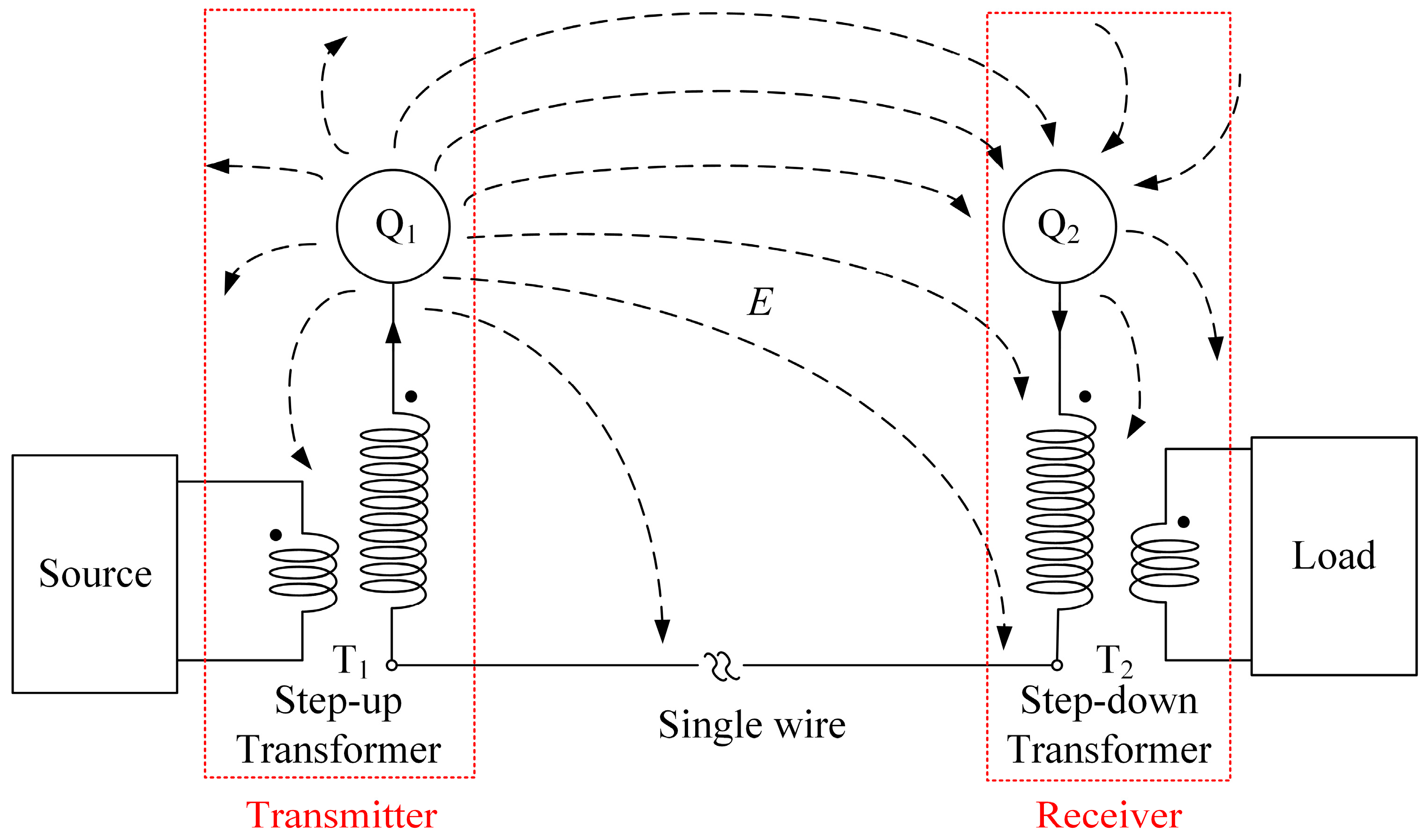
2. System Structure and Modeling

In general, single-wire ECPT systems mainly contain a source, transmitter, receiver, and load, as shown in Figure 1. The source is usually achieved by a converter, such as half-bridge, full-bridge, and others, which serves as power supply for the whole system. The transmitter includes a step-up transformer T1 and a metal conductor Q1 that obtains the power from the source and transfers it to the receiver through coupling electric field. The receiver comprises a metal conductor Q2 and step-down transformer T2 that provides power for a resistant load. Particularly, the coupling capacitance between Q1 and Q2 can be expressed as C 12 = 4 π ε 0 r 2 / d when both Q1 and Q2 are spherical metal conductors of radius r, ε 0 is the permittivity of vacuum.

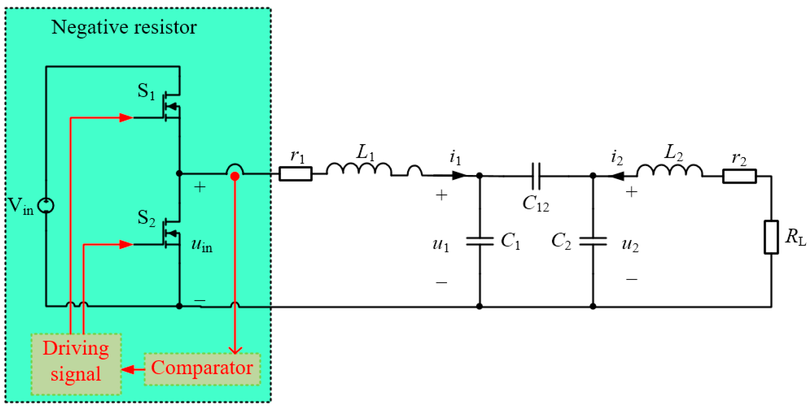
2.1. Discrete State Space Model

As illustrated in Figure 1, the transformer T1 on the transmitting side only plays a role in boosting the input voltage, similarly, the transformer T2 on the receiving side only serves to reduce the output voltage, the source reflected to the high-voltage coil on the transmitting side is proportional to the original voltage source or current source, and the load reflected to the low-voltage coil on the receiving side is also proportional to the actual load. Thus, the system shown in Figure 1 can be simplified to a two-coil equivalent circuit, as shown in Figure 2, it is a detailed schematic of the entire single-wire ECPT system based on the nonlinear PT model, which includes a half-bridge converter, coil inductance L1 and L2, internal resistance r1 and r2, parasitic capacitance C1 and C2, coupling capacitor C12, and load resistance RL. It is important to note that the half-bridge converter is used to realize a negative resistor with the characteristics of high power nonlinear gain saturation, thus attaining a PT-symmetric mode of the entire single-wire ECPT system. Besides, the implementation of the negative resistor is not limited to half-bridge converter.
The dynamics of this nonlinear PT-symmetric circuit in Figure 2 can be fully described by the discrete state space equations as follows
{ d i 1 d t = r 1 L 1 i 1 1 L 1 u 1 + 1 L 1 u in d u 1 d t = ( C 12 + C 2 ) ( C 12 C 1 + C 12 C 2 + C 1 C 2 ) i 1 + C 12 ( C 12 C 1 + C 12 C 2 + C 1 C 2 ) i 2 d i 2 d t = ( r 2 + R L ) L 2 i 2 1 L 2 u 2 d u 2 d t = C 12 ( C 12 C 1 + C 12 C 2 + C 1 C 2 ) i 1 + ( C 12 + C 1 ) ( C 12 C 1 + C 12 C 2 + C 1 C 2 ) i 2
where i1 and i2 are currents flowing through the inductors, u1 and u2 are voltages across the capacitors, uin is the output voltage of the half-bridge converter.
Equation (1) can be solved immediately when uin is given. Figure 3 shows the waveform of uin at two different operation cases, as well as i1 and the gate drive signals of S1 and S2 (vg_S1 and vg_S2). To simplify the analysis, the delay time and dead time is not considered in modeling. As shown in Figure 3, the voltage uin depends on current waveform i1 across the LC (inductance and capacitance) tank of the transmitter [29]. Therefore, assuming the direction of current i1 shown in Figure 2 is positive, uin is defined as
u in = sgn ( i 1 ) + 1 2 V in
where Vin is the input dc voltage of the half-bridge converter.

2.2. Dynamic Modeling by CMT

The state space averaging method is difficult to apply in the steady-state analysis and transient-state analysis of the system based on circuit theory because of the fast varying state variables, in and un, n = 1, 2. To overcome these problems, a dynamic modeling method based on coupled modes is proposed [29].
The voltages and currents of coupled resonators can be represented by coupled modes
a n = C n 2 u n + j L n 2 i n = A n e j ( ω t + θ n ) ,   n = 1 , 2
where the subscript 1 (or 2) denotes the transmitter (or receiver), the variables an are defined so that the energy contained in resonators n is | a n | 2 , ω is the operating angular frequency of system, the variables An represent the amplitudes of the modes while the variables θn refers to the phase of the modes. Both An and θn vary slowly with time.
To determine the dynamic equations of the coupled modes, representing the currents flowing through inductors and the voltage across capacitors by Equation (3), and substituting them and Equation (2) into Equation (1), the dynamic equations of the coupled modes can be derived out from the discrete state space model. Then, by assuming the slowly varying variables An and θn are constant during a switching period, and eliminating the high-frequency terms by averaging method [30], while remaining the low-frequency characteristics, thus, the time-invariant averaged model can be described by
{ d A 1 d t = r 1 2 L 1 A 1 C 12 C 1 C 2 2 ( C 12 C 1 + C 12 C 2 + C 1 C 2 ) 1 L 2 C 2 A 2 sin ( θ 2 θ 1 ) 1 2 L 1 1 π V in d θ 1 d t = ω + 1 2 1 L 1 C 1 + ( C 12 + C 2 ) C 1 2 ( C 12 C 1 + C 12 C 2 + C 1 C 2 ) 1 L 1 C 1 + C 12 C 1 C 2 2 ( C 12 C 1 + C 12 C 2 + C 1 C 2 ) 1 L 2 C 2 A 2 A 1 cos ( θ 2 θ 1 ) d A 2 d t = ( r 2 + R L ) 2 L 2 A 2 + C 12 C 1 C 2 2 ( C 12 C 1 + C 12 C 2 + C 1 C 2 ) 1 L 1 C 1 A 1 sin ( θ 2 θ 1 ) d θ 2 d t = ω + 1 2 1 L 2 C 2 + C 12 C 1 C 2 2 ( C 12 C 1 + C 12 C 2 + C 1 C 2 ) 1 L 1 C 1 A 1 A 2 cos ( θ 2 θ 1 ) + ( C 12 + C 1 ) C 2 2 ( C 12 C 1 + C 12 C 2 + C 1 C 2 ) 1 L 2 C 2
The derivative of Equation (3) over time can be defined as
d a n d t = d A n d t e j ( ω t + θ n ) j ( ω + d θ n d t ) A n e j ( ω t + θ n ) ,   n = 1 , 2
Substituting Equation (4) into Equation (5), the dynamic equations of coupled modes for single-wire ECPT system can be derived as
{ d a 1 d t = [ j ω 1 1 2 ( 1 + 1 + 1 k 12 C 2 C 1 1 + 1 k 12 C 2 C 1 + C 2 C 1 ) + g 0 τ 10 ] a 1 j ω 2 k 12 2 ( C 1 + C 2 C 1 C 2 k 12 + 1 ) a 2 d a 2 d t = [ j ω 2 1 2 ( 1 + 1 + 1 k 12 C 1 C 2 1 + 1 k 12 C 1 C 2 + C 1 C 2 ) τ 20 τ L ] a 2 j ω 1 k 12 2 ( C 1 + C 2 C 1 C 2 k 12 + 1 ) a 1
where the natural resonant frequencies are defined as: ω 1 = 1 / L 1 C 1 and ω 2 = 1 / L 2 C 2 . The loss rates are denoted as: τ 10 = r 1 / 2 L 1 , τ 20 = r 2 / 2 L 2 , and τ L = R L / 2 L 2 . The electric-field coupling coefficient between transmitter and receiver is k 12 = C 12 / C 1 C 2 , and the gain rate is g 0 = V in / ( π 2 L 1 | a 1 | ) .
For a long-range ECPT system, natural resonant frequencies of two LC tanks are usually close to each other ( ω 1 ω 2 ). Besides, a PT-symmetric system requires that the two natural resonant frequencies are the same ( ω 1 = ω 2 = ω 0 ). The term C12 is for the coupling capacitor that is generated by the displacement current between the metal conductors on the transmitting and receiving sides, which is much smaller than C1 and C2 in general. In addition, the values of τ 10 , τ 20 , τ L , g 0 | a 1 | and ω0k12 are relatively close in weak coupling region. Therefore, to simplify Equation (6), the simplified coupled-mode equations can be derived as follows
{ d a 1 d t = ( j ω 0 + g 0 τ 10 ) a 1 j κ a 2 d a 2 d t = ( j ω 0 τ 20 τ L ) a 2 j κ a 1
where κ = ω 0 k 12 / 2 is defined as the coupling coefficient between two modes a1 and a2.

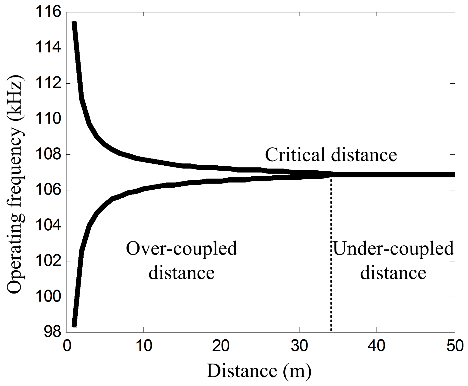
3. Analysis of Transmission Characteristics

The transmission performance, such as the power delivered to the load PL, transmission efficiency η and the operating frequency ω, can be easily derived from the steady solutions of the coupled-mode Equation (7).
Defining a 1 , 2 e j ω t , the operating frequency in the steady state can be obtained by characteristic equation
[ j ( ω ω 0 ) g 0 + τ 10 ] [ j ( ω ω 0 ) + τ 20 + τ L ] + κ 2 = 0
Separating the real and imaginary parts of Equation (8), it can be see that there are two equations to be satisfied, as follows
{ ( ω ω 0 ) 2 + ( g 0 τ 10 ) ( τ 20 + τ L ) κ 2 = 0 ( ω ω 0 ) ( g 0 τ 10 τ 20 τ L ) = 0
By solving the above Equation (9), it can be found that there are two regions containing solutions of Equation (9), depending on the relative values of κ and τ 20 + τ L , as shown in Figure 4. In the over-coupled region ( κ τ 20 + τ L ), which is called PT-symmetric phase, the system supports two modes with two solutions of frequency ω = ω 0 + κ 2 ( τ 20 + τ L ) 2 and ω = ω 0 κ 2 ( τ 20 + τ L ) 2 , the gain coefficient is exactly balanced with all the losses of system, that is, g 0 = τ 10 + τ 20 + τ L . The mode amplitudes of two modes are equal, that is, | a 2 / a 1 | = 1 , which means | a 2 | = V in / [ π 2 L 1 ( τ 10 + τ 20 + τ L ) ] . In the under-coupled region ( κ < τ 20 + τ L ), which is called PT broken phase, only one mode is located at ω = ω 0 , the corresponding gain coefficient is g 0 = τ 10 + κ 2 / ( τ 20 + τ L ) , and the ratio of these two mode amplitudes is | a 2 / a 1 | = κ / ( τ 20 + τ L ) , that is, | a 2 | = κ V in / { π 2 L 1 [ τ 10 ( τ 20 + τ L ) + κ 2 ] } . Moreover, κ = τ 20 + τ L is the critical coupling coefficient.
Based on the above analysis of multiple solutions of the system, the power delivered to the load can be expressed as
P L = 2 τ L | a 2 | 2 = { τ L V in 2 π 2 L 1 ( τ 10 + τ 20 + τ L ) 2 ,   κ τ 20 + τ L τ L κ 2 V in 2 π 2 L 1 [ τ 10 ( τ 20 + τ L ) + κ 2 ] 2 ,   κ < τ 20 + τ L
and the transmission efficiency can be represented as
η = 2 τ L | a 2 | 2 2 τ 10 | a 1 | 2 + 2 ( τ 20 + τ L ) | a 2 | 2 × 100 % = { τ L τ 10 + τ 20 + τ L ,   κ τ 20 + τ L κ 2 τ L [ τ 10 ( τ 20 + τ L ) + κ 2 ] ( τ 20 + τ L ) ,   κ < τ 20 + τ L
From Equations (10) and (11), it can be see that the output power and transmission efficiency of the system remain constant in the over-coupled region.

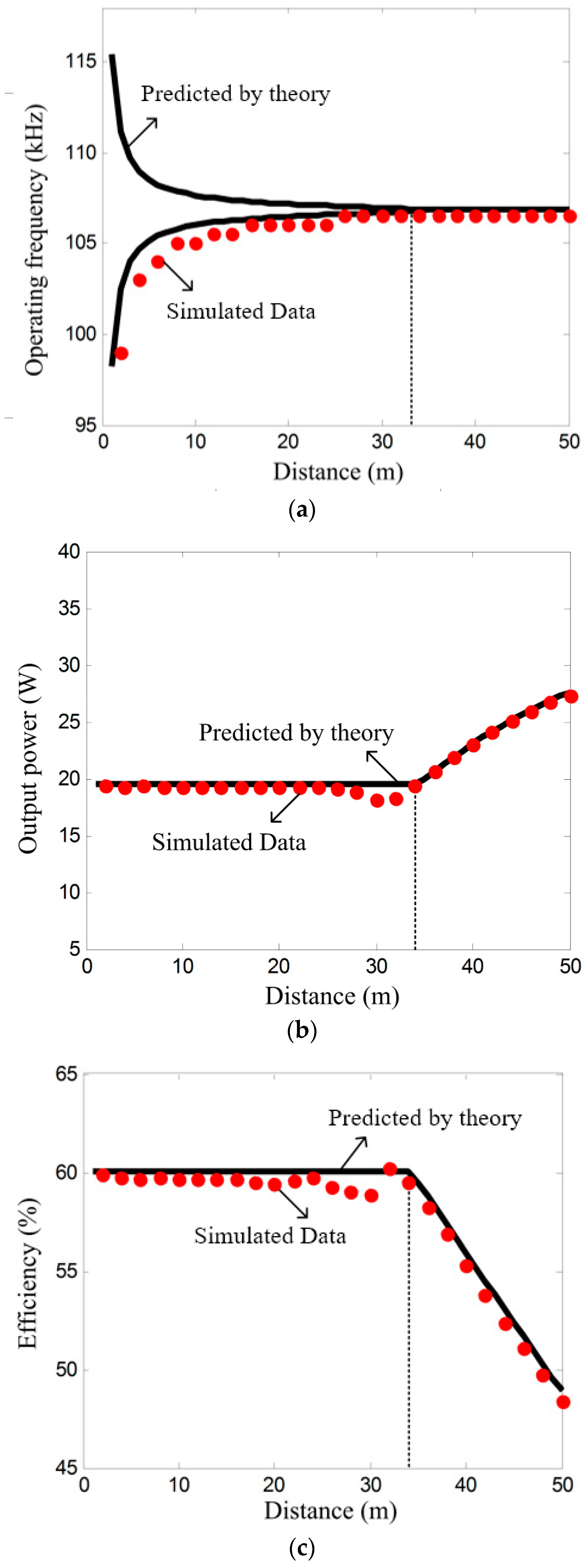
4. Comparison of Theoretical Analysis and Simulation

To show the wonderful characteristics of the actual single-wire ECPT system, two spherical metal conductors of radius 22.5 cm are adopted to generate the electric field to transfer the energy obtained from the transmitter to the receiver. The metal balls placed on the top of the PVC tube are connected to the earth through a large inductance L1 and L2 winding around the PVC tube, and the grounding side of the inductors is connected with a single metal wire to form a conductive closed loop with the upper metal balls. The capacitance between the metal balls is expressed by the coupling capacitance C12, the parasitic capacitance of the metal balls relative to the single metal wire is described by C1 and C2. The specific parameters is shown in Table 1.
Combining the specific expression of coupling capacitance C12 with the detailed expression of critical coupling coefficient κ = τ 20 + τ L , and substituting the parameters of Table 1 into it, the critical distance can be obtained
d c = 111.2 r 2 ω 0 L 2 ( r 2 + R L ) C 1 × 10 12 34.23 m
To verify the results of theoretical analysis, a circuit simulation model is built. By substituting the parameters of Table 1 into Equations (10) and (11), and combining with circuit simulation, the comparison of the results of theoretical analysis and circuit simulation are shown in Figure 5.
As illustrated in Figure 5, the circuit simulation results are consistent with the theoretical analysis. In the over-coupled region ( d d c ), the system operates in low-frequency mode, that is, the operating frequency automatically meet the condition of ω = ω 0 κ 2 ( τ 20 + τ L ) 2 without any tuning, the output power is constant near 19 W, and the transmission efficiency is near stable at 60% over a distance of 34 m with a deviation less than 5%. The internal resistances of the inductor is 50 Ω in our simulation, the efficiency of the system can reach 90% if the internal resistance is further reduced. In addition, in the under-coupled region, the operating frequency is fixed at natural resonant frequency, f 0 = 106.8   kHz .

5. Discussion and Conclusions

This paper proposes a new nonlinear PT-symmetric model for single-wire ECPT system based on CMT, which is an extraordinary progress compared to traditional ECPT system. The proposed model can be used to achieve robust power transmission via electric field with constant output power and high constant transmission efficiency over a wide range of transmission distance. Based on the proposed model, the negative resistor, which is used to realize a gain rate g0, is achieved by a half-bridge converter, and the control of half-bridge converter depends only on the information of current flowing through the resonant inductor of transmitter, which is very simple and feasible. Moreover, the simulation results are consistent with the theoretical analysis, the load can obtain stable power of 19 W with constant efficiency of 60% over distances in excess of 34 m.

Acknowledgments

This project was supported by the Key Program of National Natural Science Foundation of China (grant no. 51437005).

Author Contributions

Xujian Shu established the model, analyzed the characteristics of the proposed model, and implemented the simulation and wrote this article; Bo Zhang guided and revised the paper.

Conflicts of Interest

The authors declare no conflict of interest.

References

  1. Marincic, A.S. Nikola Tesla and the wireless transmission of energy. IEEE Trans. Power Appar. Syst. 1982, PAS-101, 4064–4068. [Google Scholar] [CrossRef]
  2. Tesla, N. System of Transmission of Electrical Energy. U.S. Patent 645,576, 20 March 1900. [Google Scholar]
  3. Pudur, R.; Hanumante, V.; Shukla, S.; Kumar, K. Wireless power transmission: A survey. In Proceedings of the IEEE International Conference on Recent Advances and Innovations in Engineering, Jaipur, India, 9–11 May 2014. [Google Scholar] [CrossRef]
  4. Liu, C.; Hu, A.P.; Budhia, M. A generalized coupling model for capacitive power transfer systems. In Proceedings of the IECON 2010, 36th Annual Conference of the IEEE Industrial Electronics Society, Glendale, AZ, USA, 7–10 November 2010. [Google Scholar] [CrossRef]
  5. Kurs, A.; Karalis, A.; Moffatt, R.; Joannopoulos, J.D. Wireless power transfer via strongly coupled magnetic resonances. Science 2007, 317, 83–86. [Google Scholar] [CrossRef] [PubMed]
  6. Mcspadden, J.O.; Mankins, J.C. Space solar power programs and microwave wireless power transmission technology. IEEE Microw. Mag. 2002, 3, 46–57. [Google Scholar] [CrossRef]
  7. Howell, J.T.; O’Neill, M.J.; Fork, R.L. Advanced receiver/converter experiments for laser wireless power transmission. In Proceedings of the Solar Power from Space (SPS04) and 5th Wireless Power Transmission (WPT5) Conference, Granada, Spain, 30 June–2 July 2004. [Google Scholar]
  8. Covic, F.A.; Boys, J.T.; Kissin, M.L.; Lu, H.G. A three-phase inductive power transfer system for roadway. IEEE Trans. Ind. Electron. 2007, 54, 3370–3378. [Google Scholar] [CrossRef]
  9. Huang, C.Y.; Boys, J.T.; Covic, G.A. LCL pickup circulating current controller for inductive power transfer systems. IEEE Trans. Power Electron. 2013, 28, 2081–2093. [Google Scholar] [CrossRef]
  10. Hao, H.; Covic, G.A.; Boys, J.T. Aparallel topology for inductive power transfer power supplies. IEEE Trans. Power Electron. 2014, 29, 1140–1151. [Google Scholar] [CrossRef]
  11. Choi, B.; Nho, J.; Cha, H.; Ahn, T.; Choi, S. Design and implementation of low-profile contactless battery charger using planar printed circuit board windings as energy transfer device. IEEE Trans. Ind. Electron. 2004, 51, 140–147. [Google Scholar] [CrossRef]
  12. Adachi, S.I.; Sato, F.; Kikuchi, S.; Matsuki, H. Consideration of contactless power station with selective excitation to moving robot. IEEE Trans. Magn. 1999, 35, 3583–3585. [Google Scholar] [CrossRef]
  13. Lee, B.; Kiani, M.; Ghovanloo, M. A triple-loop inductive power transmission system for biomedical application. IEEE Trans. Biomed. Circuits Syst. 2016, 10, 138–148. [Google Scholar] [CrossRef] [PubMed]
  14. Hui, S.Y.R. Magnetic resonance for wireless power transfer. IEEE Power Electron. Mag. 2016, 3, 14–31. [Google Scholar] [CrossRef]
  15. Thomas, E.M.; Heebl, J.D.; Pfeiffer, C.; Grbic, A. A power link study of wireless non-radiative power transfer systems using resonant shielded loops. IEEE Trans. Circuits Syst. I Regul. Pap. 2012, 59, 2125–2136. [Google Scholar] [CrossRef]
  16. Celeste, A.; Jeanty, P.; Pignolet, G. Case study in reunion island. Acta Astronaut. 2004, 54, 253–258. [Google Scholar] [CrossRef]
  17. Yugami, H.; Kanamori, Y.; Arashi, H. Field experiment of laser energy transmission and laser to electric conversion. In Proceedings of the Intersociety Energy Conversion Engineering Conference, Honolulu, HI, USA, 27 July–1 August 1997. [Google Scholar] [CrossRef]
  18. Kawashima, N.; Takeda, K. Laser energy transmission for a wireless energy supply to robots. Robot. Autom. Constr. 2008. [Google Scholar] [CrossRef]
  19. Steinsiek, F.; Foth, W.P.; Weber, K.H. Wireless power transmission experiment as an early contribution to planetary exploration missions. In Proceedings of the 54th International Astronautical Congress of the International Astronautical Federation, the International Academy of Astronautics, the International Institute of Space Law, Bremen, Germany, 29 September–3 October 2003; Volume 3, pp. 169–176. [Google Scholar] [CrossRef]
  20. Hyde, R.A.; Dixit, S.N.; Weisberg, A.H.; Rushford, M. Eyeglass: Large aperture diffractive space telescope. Proc. SPIE Int. Soc. Opt. Eng. 2002, 4849, 28–39. [Google Scholar]
  21. Tetsuo, N.; Tianhongshu, P.; Yong, L. Great power wireless transmission technology. Electron. Des. Appl. 2007, 6, 42–54. [Google Scholar]
  22. Mayordomo, I.; Drager, T.; Spies, P.; Bernhard, J.; Pflaum, A. An overview of technical challenges and advances of inductive wireless power transmission. Proc. IEEE 2013, 101, 1302–1311. [Google Scholar] [CrossRef]
  23. Dukju, A.; Songcheol, H. A transmitter or a receiver consisting of two strongly coupled resonators for enhanced resonant coupling in wireless power transfer. IEEE Trans. Ind. Electron. 2014, 61, 1193–1203. [Google Scholar] [CrossRef]
  24. Strebkov, D.S.; Avramenko, S.V.; Nekrasov, A.I. Single-wire electric power system for renewable-based electric grid. New Energy Technol. Mag. 2001, 20–25. Available online: http://ptp.irb.hr/upload/mape/kuca/07_Dmitry_S_Strebkov_SINGLE-WIRE_ELECTRIC_POWER_SYSTEM_FOR_RE.pdf (accessed on 18 January 2018).
  25. Dmitry, S.S.; Wang, X. Single-wire transmission system used for rural areas. Rural Electrification 2001, 49–51. [Google Scholar] [CrossRef]
  26. Jackson, S. Pesn Open Source Project Tesla Wireless Power Transmission. Available online: http://www.apparentlyapparel.com/uploads/5/3/5/6/5356442/jacksons_tesla-wireless-coil_instructions_apr-21-2011.pdf (accessed on 21 April 2011).
  27. Assawaworrarit, S.; Yu, X.; Fan, S. Robust wireless power transfer using a nonlinear parity–time-symmetric circuit. Nature 2017, 546, 387–390. [Google Scholar] [CrossRef] [PubMed]
  28. Schindler, J.; Lin, Z.; Lee, J.M.; Ramezani, H.; Ellis, F.M.; Kottos, T. PT-symmetric electronics. J. Phys. A Math. Theor. 2012, 45, 2077–2082. [Google Scholar] [CrossRef]
  29. Li, H.; Wang, K.; Huang, L.; Chen, W.; Yang, X. Dynamic modeling based on coupled modes for wireless power transfer systems. IEEE Trans. Power Electron. 2015, 30, 6245–6253. [Google Scholar] [CrossRef]
  30. Sanders, J.A.; Verhulst, F. Averaging Methods in Nonlinear Dynamical Systems; Springer: New York, NY, USA, 1985. [Google Scholar]
Figure 1. The circuit diagram of the single-wire ECPT system.
Energies 11 00532 g001
Figure 2. Equivalent circuit topology of a half-bridge type single-wire ECPT system.
Energies 11 00532 g002
Figure 3. Implementation of the negative resistor with the characteristics of nonlinear gain saturation.
Energies 11 00532 g003
Figure 4. Theoretical values of the operating frequency. The critical distance is about 34 m, which is far greater than the transmission distance of the typical WPT system.
Energies 11 00532 g004
Figure 5. Calculated and simulated values of operating frequency, output power, and transmission efficiency as a function of distance between transmitter and receiver, the black solid line is the theoretical values derived from the equations of system, the red solid point is the simulated values by the circuit simulation: (a) operating frequency versus distance; (b) output power versus distance; (c) efficiency versus distance.
Energies 11 00532 g005
Table 1. Parameters of the single-wire ECPT system.
ParametersValues
Vin200 V
L163.4 mH
L263.4 mH
C135 pF
C235 pF
r150 Ω
r250 Ω
RL150 Ω
r22.5 cm
f0106.8 kHz

