Adaptive Backstepping Control with Online Parameter Estimator for a Plug-and-Play Parallel Converter System in a Power Switcher

Abstract
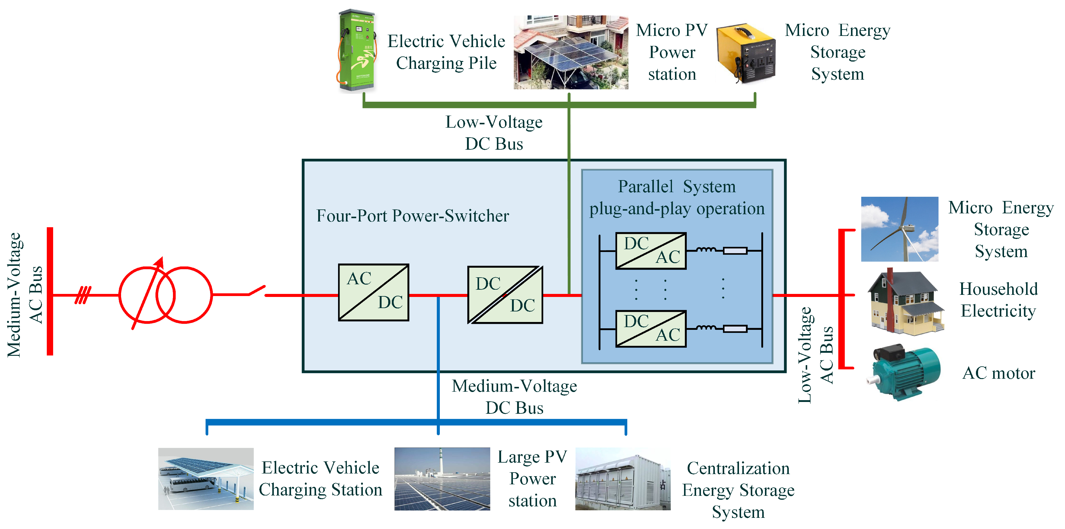
:1. Introduction
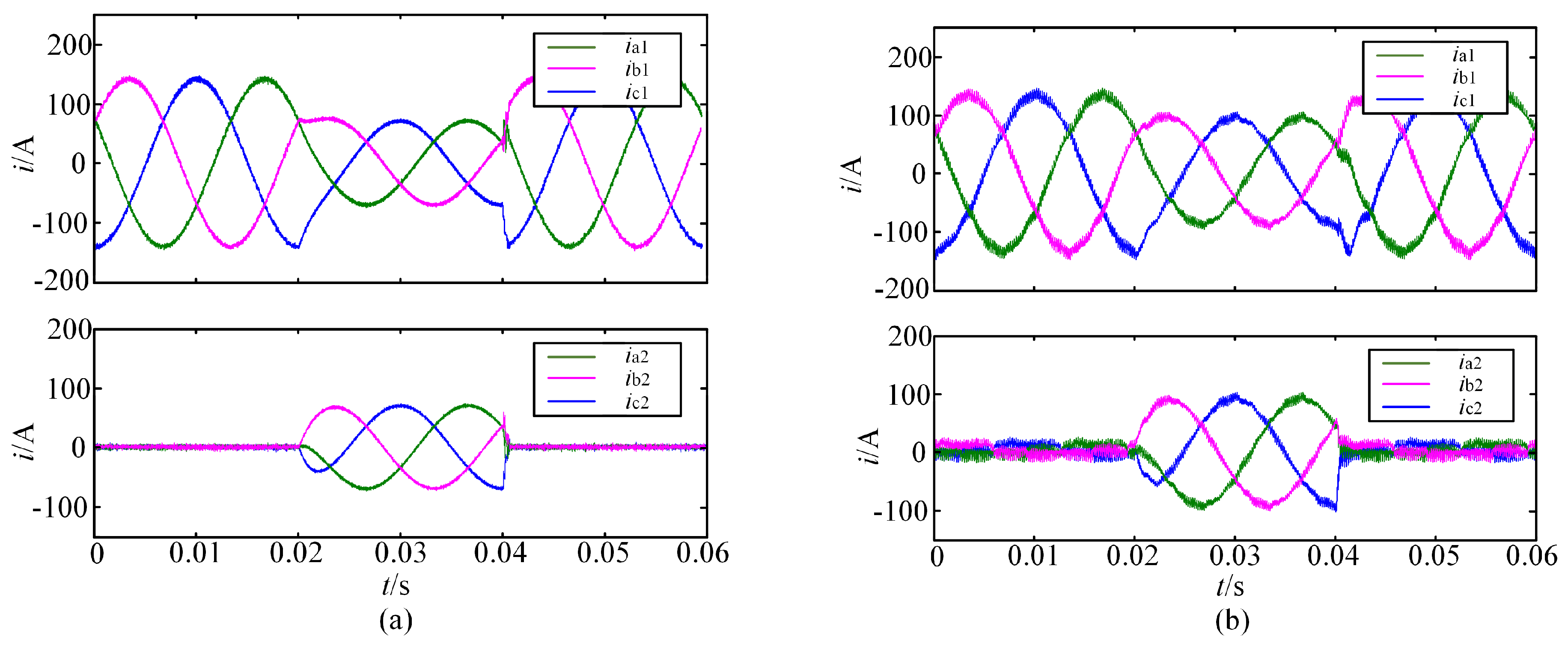
2. Circulating Current Analysis
3. System Model and Control Design
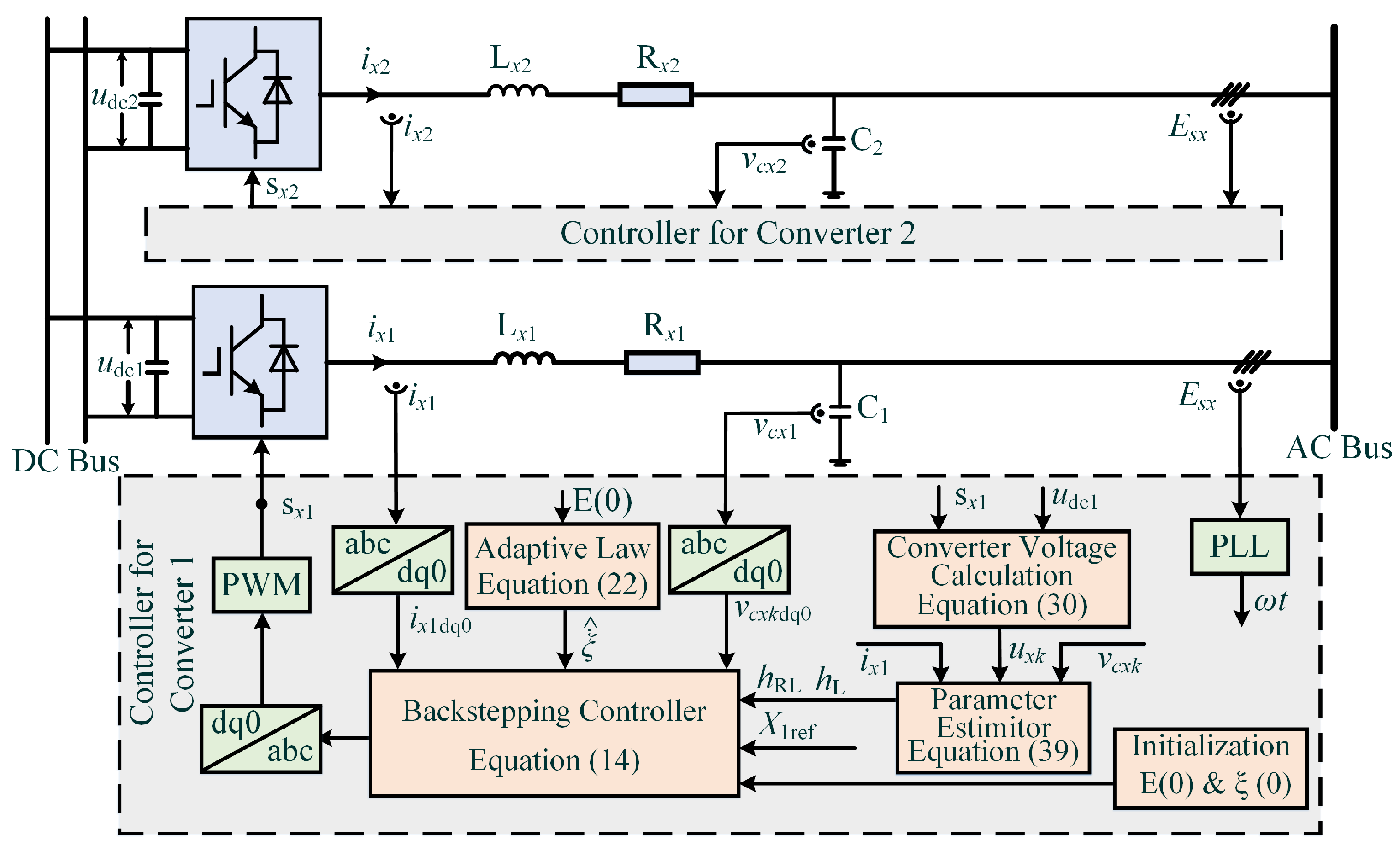
3.1. System Model
3.2. Backstepping Controller Design
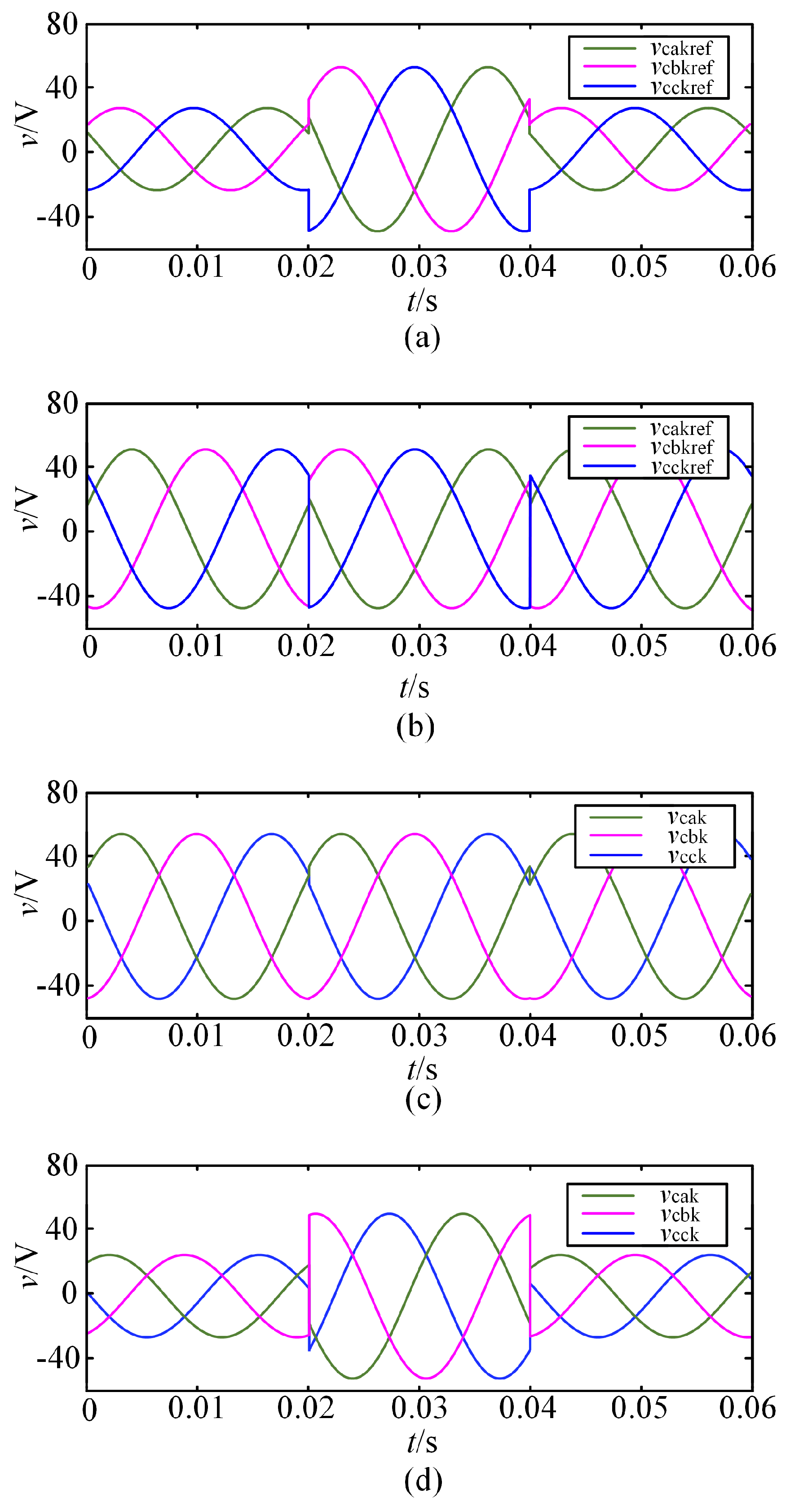
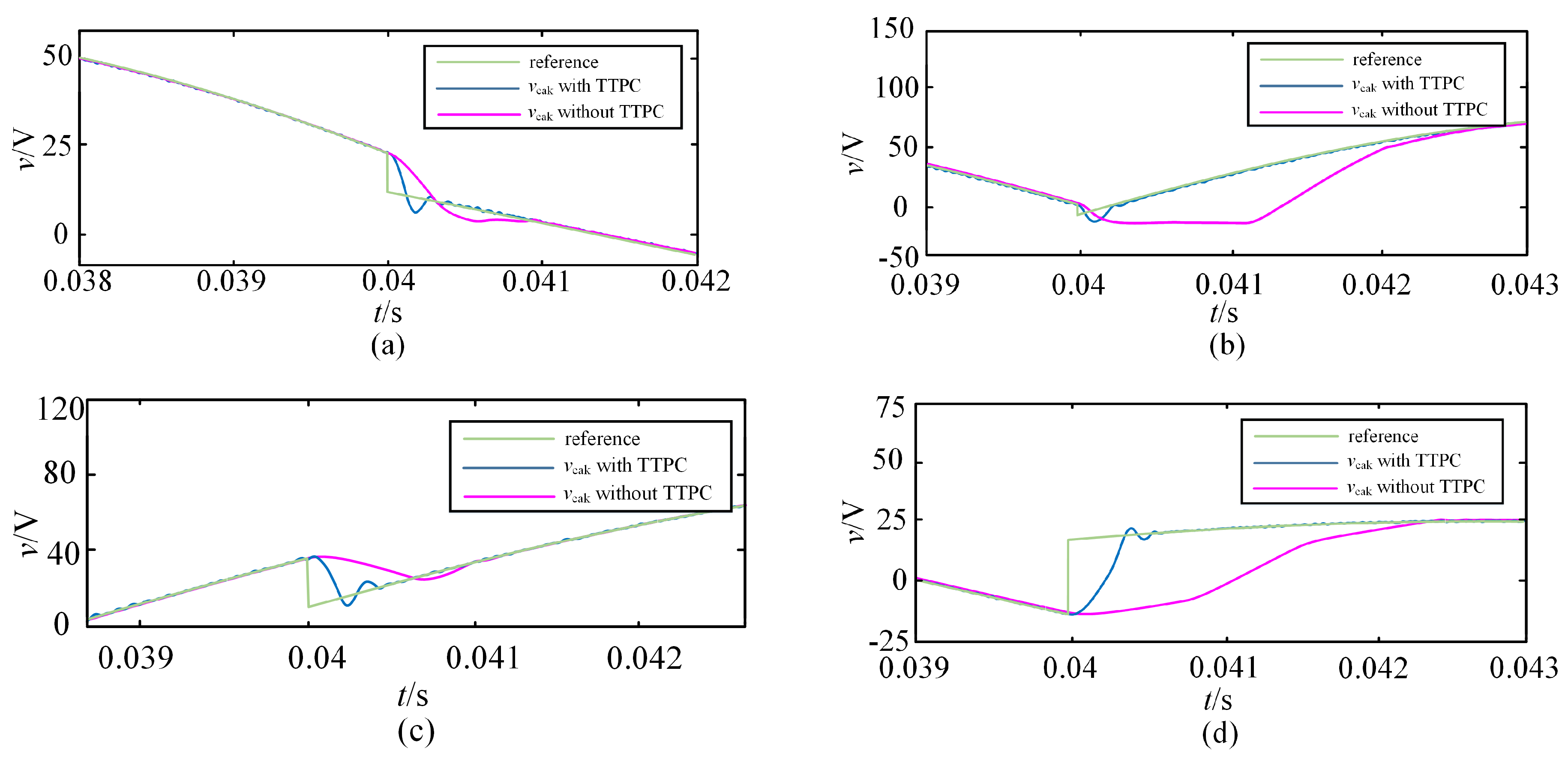
3.3. Transient Tracking Performance Control
3.4. Online Parameter Estimator Design
3.5. Block Diagram of the Proposed Control Strategy
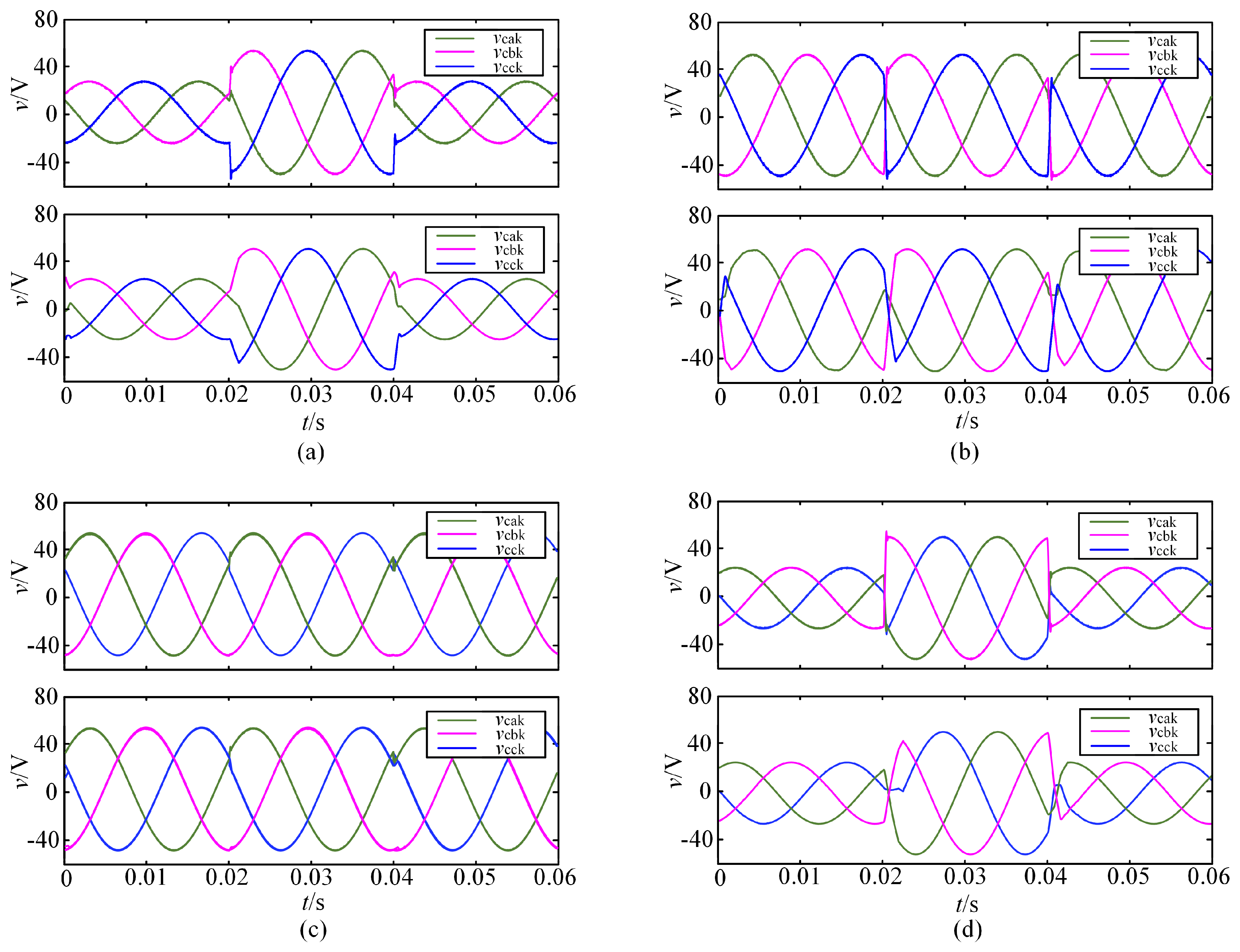
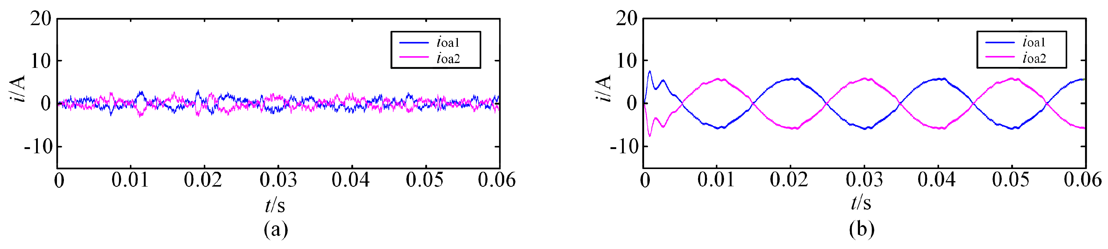
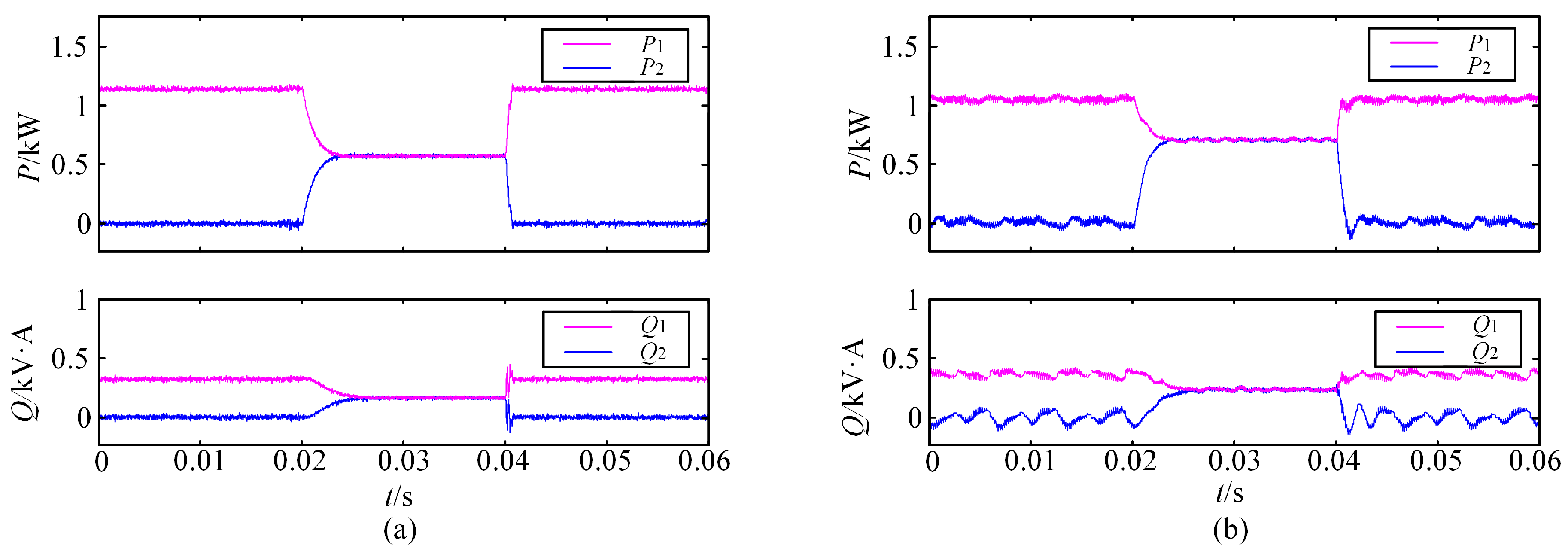
4. Simulation Study
5. Conclusions
Author Contributions
Funding
Conflicts of Interest
References
- Wanxing, S.; Qing, D.; Xiaoli, M.; Haitao, L.; Changkai, S. Research on the AC & DC seamless-hybrid fluent power distribution system following the power electronics evolution. Proc. CSEE 2017, 37, 1877–1888. [Google Scholar] [CrossRef]
- Iyer, A.R.; Kandula, R.P.; Moghe, R.; Hernandez, J.E.; Lambert, F.C.; Divan, D. Validation of the plug-and-play ac/ac power electronics building block (AC-PEBB) for medium-voltage grid control applications. IEEE Trans. Ind. Appl. 2014, 50, 3549–3557. [Google Scholar] [CrossRef]
- Mohammad, M.; Parisa, M.S.; Ali, M. Analysis and output voltage control of a high-efficiency converter for DC microgrids. In Proceedings of the IEEE Conference on Industrial Electronics Society, Washington, DC, USA, 21–23 October 2018. [Google Scholar]
- Rifkin, J. Third Industrial Revolution: How Lateral Power Is Transforming Energy, the Economy, and the World; Palgrave Macmillan: New York, NY, USA, 2011; pp. 31–46. [Google Scholar]
- Ghaffarianfar, M.; Hajizadeh, A. Voltage stability of low-voltage distribution grid with high penetration of photovoltaic power units. Energies 2018, 11, 1960. [Google Scholar] [CrossRef]
- Ashabani, M.; Mohamed, I.; Mirsalim, M.; Aghashabani, M. Multivariable droop control of synchronous current converters in weak grids/micro-grids with decoupled dq-axes currents. IEEE Trans. Smart Grid 2015, 6, 1610–1620. [Google Scholar] [CrossRef]
- Xia, Y.; Wei, W.; Peng, Y.; Yang, P.; Yu, M. Decentralized coordination control for parallel bidirectional power converters in a grid-connected dc micro-grid. IEEE Trans. Smart Grid 2017. [Google Scholar] [CrossRef]
- Yang, J.; Cui, H.; Li, S.; Zolotas, A. Optimized active disturbance rejection control for DC-DC buck converters with uncertainties using a reduced-order GPI observer. IEEE Trans. Circuits Syst. I Regul. Pap. 2018, 65, 832–841. [Google Scholar] [CrossRef]
- Feng, G.; Huang, L.; Zhu, D. High performance control of induction motor based on auto-disturbance rejection controller. Proc. CSEE 2001, 21, 55–58. [Google Scholar] [CrossRef]
- Song, J.; Gan, Z.; Han, J. Study of active disturbance rejection controller on filtering. Control Decis. 2003, 18, 55–58. [Google Scholar] [CrossRef]
- Wang, B.; Shen, Z.; Liu, H.; Hu, J. Linear ADRC direct current control of grid-connected inverter with LCL filter for both active damping and grid voltage induced current distortion suppression. IET Power Electron. 2018, 11, 1748–1755. [Google Scholar] [CrossRef]
- Yang, N.; Gao, F.; Paire, D.; Miraoui, A.; Liu, W. Distributed control of multi-time scale DC micro-grid based on ADRC. IET Power Electron. 2017, 10, 329–337. [Google Scholar] [CrossRef]
- Wang, J.; Li, S.; Yang, J.; Wu, B.; Li, Q. Extended state observer-based sliding mode control for PWM-based DC–DC buck power converter systems with mismatched disturbances. IET Control Theory Appl. 2014, 9, 579–586. [Google Scholar] [CrossRef]
- Zhang, D.; Yao, X.; Wu, Q.; Song, Z. ADRC based control for a class of input time delay systems. J. Syst. Eng. Electron. 2017, 28, 1210–1220. [Google Scholar] [CrossRef]
- Xue, W.; Bai, W.; Yang, S.; Song, K.; Huang, Y.; Xie, H. ADRC with adaptive extended state observer and its application to air-fuel ratio control in gasoline engines. IEEE Trans. Ind. Electron. 2015, 62, 5847–5857. [Google Scholar] [CrossRef]
- Lia, Y.; You, J.; Yang, J.; Wang, Z.; Jin, L. Disturbance-observer-based model predictive control for battery energy storage system modular multilevel converters. Energies 2018, 11, 2285. [Google Scholar] [CrossRef]
- Yang, W.; Zhang, H.; Li, J.; Zhang, A.; Zhou, Y.; Wang, J. PIDR sliding mode current control with online inductance estimator for VSC-MVDC system converter stations under unbalanced grid voltage conditions. Energies 2018, 11, 2599. [Google Scholar] [CrossRef]
- Yan, S.; Zhang, A.; Zhang, H.; Wang, J.; Cai, B. Optimized and coordinated model predictive control scheme for DFIGs with dc-based converter system. J. Mod. Power Syst. Clean Energy 2017, 5, 620–630. [Google Scholar] [CrossRef]
- Vazquez, S.; Leon, J.I.; Franquelo, L.G.; Rodriguez, J.; Young, H.A.; Marquez, A.; Zanchetta, P. Model predictive control: A review of its applications in power electronics. IEEE Ind. Electron. Mag. 2014, 8, 16–31. [Google Scholar] [CrossRef]
- Guo, C.J.; Zhang, A.M.; Zhang, H.; Ren, Z.G.; Zhang, L. A model predictive control method for bidirectional interfacing converters in hybrid ac/dc micro-grids. J. Xi’an Jiaotong Univ. 2018, 52, 40–46. [Google Scholar] [CrossRef]
- Ramírez, R.O.; Espinoza, J.R.; Melín, P.E.; Reyes, M.E.; Espinosa, E.E.; Silva, C.; Maurelia, E. Predictive controller for a three-phase/single-phase voltage source converter cell. IEEE Tran. Ind. Inform. 2014, 10, 1878–1889. [Google Scholar] [CrossRef]
- An, F.; Song, W.; Yang, K.; Hou, N.; Ma, J. Improved dynamic performanceof dual active bridge dc-dc converters using MPC scheme. IET Power Electron. 2018, 11, 1756–1765. [Google Scholar] [CrossRef]
- Hooman, G.; Ali, M. Predictive set point modulation technique to enhance the dynamic response of a power system. In Proceedings of the IEEE Applied Power Electronics Conference and Exposition, Tampa, FL, USA, 26–30 March 2017; pp. 1134–1140. [Google Scholar] [CrossRef]
- Young, H.A.; Perez, M.A.; Rodriguez, J. Analysis of finite-control-set model predictive current control with model parameter mismatch in a three-phase inverter. IEEE Trans. Ind. Electron. 2016, 63, 3100–3107. [Google Scholar] [CrossRef]
- Mohammad, G.; Saeed, L. Control of flywheel energy storage systems in presence of uncertainties. IEEE Trans. Sustain. Energy 2018. [Google Scholar] [CrossRef]
- Zhang, Y.; Kang, Y.; Chen, J. The zero-sequence circulating currents between parallel three-phase inverters with three-pole transformers and reactors. In Proceedings of the IEEE Applied Power Electronics Conference and Exposition, Dallas, TX, USA, 19–23 March 2006; pp. 1710–1715. [Google Scholar] [CrossRef]
- Sun, X.; Wong, L.; Lee, Y.; Xu, D. Design and analysis of an optimal controller for parallel multi-inverter systems. IEEE Trans. Circuits Syst. II Express Briefs 2006, 53, 56–61. [Google Scholar] [CrossRef]
- Lia, Y.; Chen, H.C. Simplified PWM with switching constraint method to prevent circulating currents for paralleled bidirectional AC/DC converters in grid-tied system using graphic analysis. IEEE Trans. Ind. Electron. 2015, 62, 4573–4586. [Google Scholar] [CrossRef]
- Zhang, X.; Chen, J.; Ma, Y.; Wang, Y.; Xu, D. Bandwidth expansion method for circulating current control in parallel three-phase PWM converter connection system. IEEE Trans. Power Electron. 2014, 29, 6847–6856. [Google Scholar] [CrossRef]
- Zhang, X.; Zhang, W.; Chen, J.; Xu, D. Deadbeat control strategy of circulating currents in parallel connection system of three-phase PWM converter. IEEE Trans. Energy Convers. 2014, 29, 406–417. [Google Scholar] [CrossRef]
- Zhang, Y.; Yu, M.; Liu, F.; Li, S.; Wang, J.; Kang, Y. Instantaneous current share method for modular UPS through virtual impedance. In Proceedings of the IEEE Conference on Industrial Electronics Society, Melbourne, Australia, 7–10 November 2011; pp. 1384–1389. [Google Scholar] [CrossRef]
- Sun, B.; Liu, H.; Wu, H.; Wang, W. A suppression method of circulating current in parallel photovoltaic system based on virtual impedance. In Proceedings of the IEEE Conference on International Power Electronics and Motion Control, Hefei, China, 22–26 May 2016; pp. 1532–1538. [Google Scholar] [CrossRef]
- Shi, H.; Zhuo, F.; Zhang, D.; Geng, Z.; Wang, F. Adaptive implementation strategy of virtual impedance for paralleled inverters UPS. In Proceedings of the IEEE Energy Conversion Congress and Exposition, Pittsburgh, PA, USA, 14–18 September 2014; pp. 158–162. [Google Scholar] [CrossRef]
- Cai, J.; Chen, C.; Liu, P.; Duan, S. Adaptive current-sharing control strategy with virtual circulating impedance for parallel operation of UPS. In Proceedings of the IEEE Energy Conversion Congress and Exposition, Montreal, QC, Canada, 22–24 September 2015; pp. 1243–1247. [Google Scholar] [CrossRef]
- Sureshkumar, R.; Ganeshkumar, S. Comparative study of proportional integral and backstepping controller for buck converter. In Proceedings of the International Conference on Emerging Trends in Electrical and Computer Technology, Nagercoil, India, 23–24 March 2011; pp. 375–379. [Google Scholar] [CrossRef]
- Song, Z.; Sun, K. Adaptive backstepping sliding mode control with fuzzy monitoring strategy for a kind of mechanical system. ISA Trans. 2014, 53, 125–133. [Google Scholar] [CrossRef] [PubMed]
- Zhang, L.; Zhang, A.; Han, J.; Zhang, H. Adaptive backstepping passivity feedback control design of static volt-ampere reactive compensator. Control Theory Appl. 2012, 29, 298–304. [Google Scholar] [CrossRef]
- Yuz, A.; Diego, L.; Jesus, L.; Luis, H.; Victor, M. Adaptive backstepping control for a fuel cell/boost converter system. IEEE J. Emerg. Sel. Top. Power Electron. 2018, 6, 686–695. [Google Scholar] [CrossRef]
- Mahdi, S.; Jafar, S.; Gholamreza, A.; Navid, R. Indirect output voltage regulation of dc-dc buck/boost converter operating in continuous and discontinuous conduction modes using adaptive backstepping approach. IET Power Electron. 2012, 6, 732–741. [Google Scholar] [CrossRef]
- Su, Q.; Dong, F.; Shen, X. Improved adaptive backstepping sliding mode control of static var compensator. Energies 2018, 11, 2750. [Google Scholar] [CrossRef]
- Sun, D.; Wang, X.; Yang, F. Backstepping direct power control without phase-locked loop of AC/DC converter under both balanced and unbalanced grid conditions. IET Power Electron. 2016, 9, 1614–1624. [Google Scholar] [CrossRef]
- Wang, G.; Wai, R.; Liao, Y. Design of backstepping power control for grid-side converter of voltage source converter-based high-voltage dc wind power generation system. IET Renew. Power Gen. 2012, 7, 118–133. [Google Scholar] [CrossRef]


| Parameters | Value |
|---|---|
| AC voltage/V | 380 |
| DC voltage/V | |
| /mH | 12 |
| 5 | |
| 1 | |
| 1 | |
| 5000 | |
| 2500 |
| Parameters | Value |
|---|---|
| Number of bridge arms | 3 |
| Snubber resistance/ | 1 |
| Snubber capacitance/F | infinity |
| Internal resistance/ | 1 |
| Forward voltage of IGBT/V | 1 |
| Forward voltage of antiparallel diodes/V | 1.2 |
© 2018 by the authors. Licensee MDPI, Basel, Switzerland. This article is an open access article distributed under the terms and conditions of the Creative Commons Attribution (CC BY) license (http://creativecommons.org/licenses/by/4.0/).
Share and Cite
Guo, C.; Zhang, A.; Zhang, H.; Zhang, L. Adaptive Backstepping Control with Online Parameter Estimator for a Plug-and-Play Parallel Converter System in a Power Switcher. Energies 2018, 11, 3528. https://doi.org/10.3390/en11123528
Guo C, Zhang A, Zhang H, Zhang L. Adaptive Backstepping Control with Online Parameter Estimator for a Plug-and-Play Parallel Converter System in a Power Switcher. Energies. 2018; 11(12):3528. https://doi.org/10.3390/en11123528
Chicago/Turabian StyleGuo, Chujia, Aimin Zhang, Hang Zhang, and Lei Zhang. 2018. "Adaptive Backstepping Control with Online Parameter Estimator for a Plug-and-Play Parallel Converter System in a Power Switcher" Energies 11, no. 12: 3528. https://doi.org/10.3390/en11123528
APA StyleGuo, C., Zhang, A., Zhang, H., & Zhang, L. (2018). Adaptive Backstepping Control with Online Parameter Estimator for a Plug-and-Play Parallel Converter System in a Power Switcher. Energies, 11(12), 3528. https://doi.org/10.3390/en11123528