A Real-Life Application of a Smart User Network

 ,
,  ,
,  ,
, 


Abstract
:1. Introduction
2. A Brief Overview of DC Microgrids Management and Control
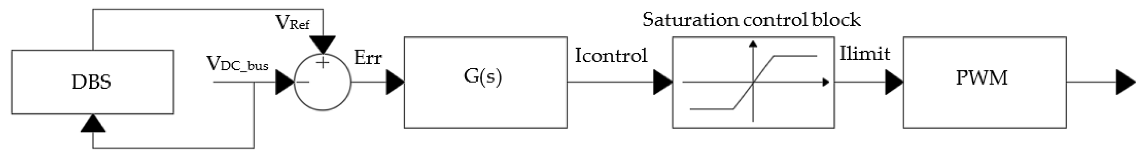
2.1. DC Control Strategy
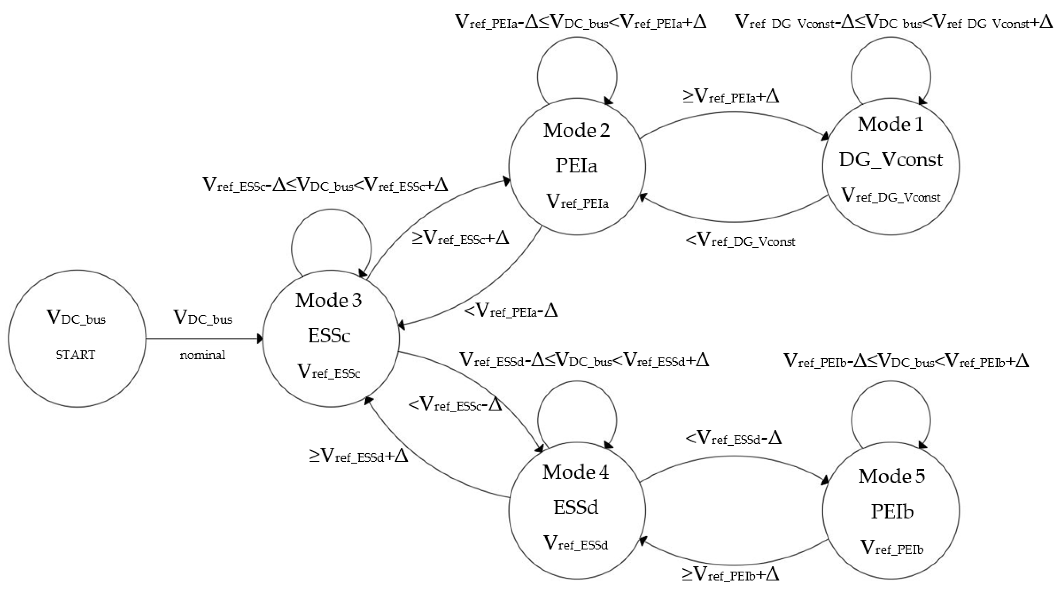
2.2. DBS Logic
- (1)
- Considering the line resistance in a Droop controlled DC microgrid, since the output voltage of each converter of the DC microgrid, cannot be exactly the same, the output current sharing accuracy is degraded;
- (2)
- The power sharing between the DC microgrid units is affected by the output impedance of the power converter and the line impedances. Hence, those virtual output-impedance loops can solve this problem. Therefore, the output impedance becomes another control variable;
- (3)
- This method is load-dependent frequency deviation, which implies a phase deviation between the output-voltage frequency of the UPS system and the input voltage provided by the grid;
- (4)
- The DC bus voltage deviation increases with the load due to the Droop action;
- (5)
- This control method is usually implemented on voltage control mode (VCM) converters, while most RES units embrace current control mode (CCM) converters;
- (6)
- The conditions of State of Charge (SOC) for storage devices are not taken into account when developing decentralized power control strategies.
2.3. Contribution of the Paper
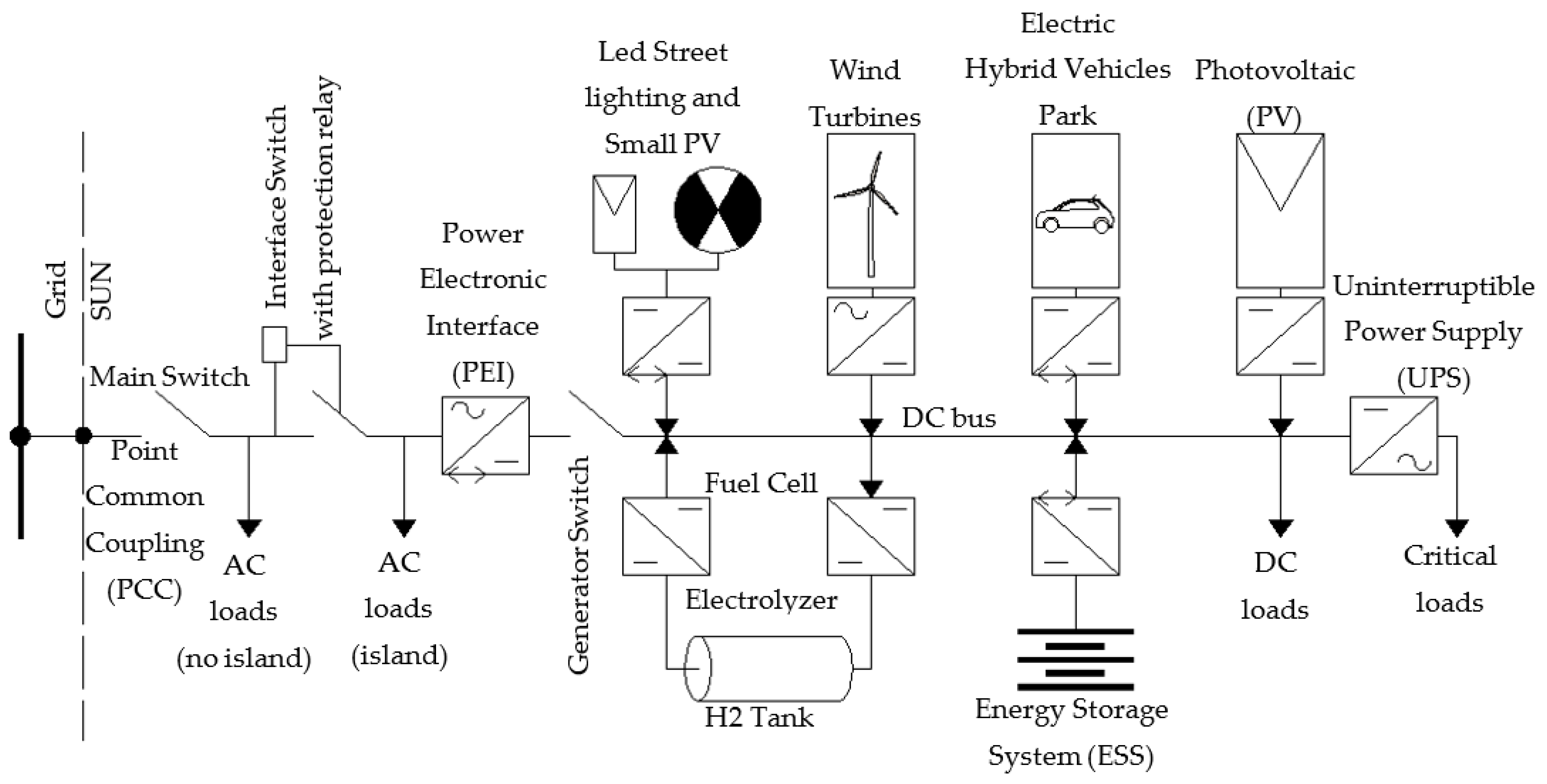
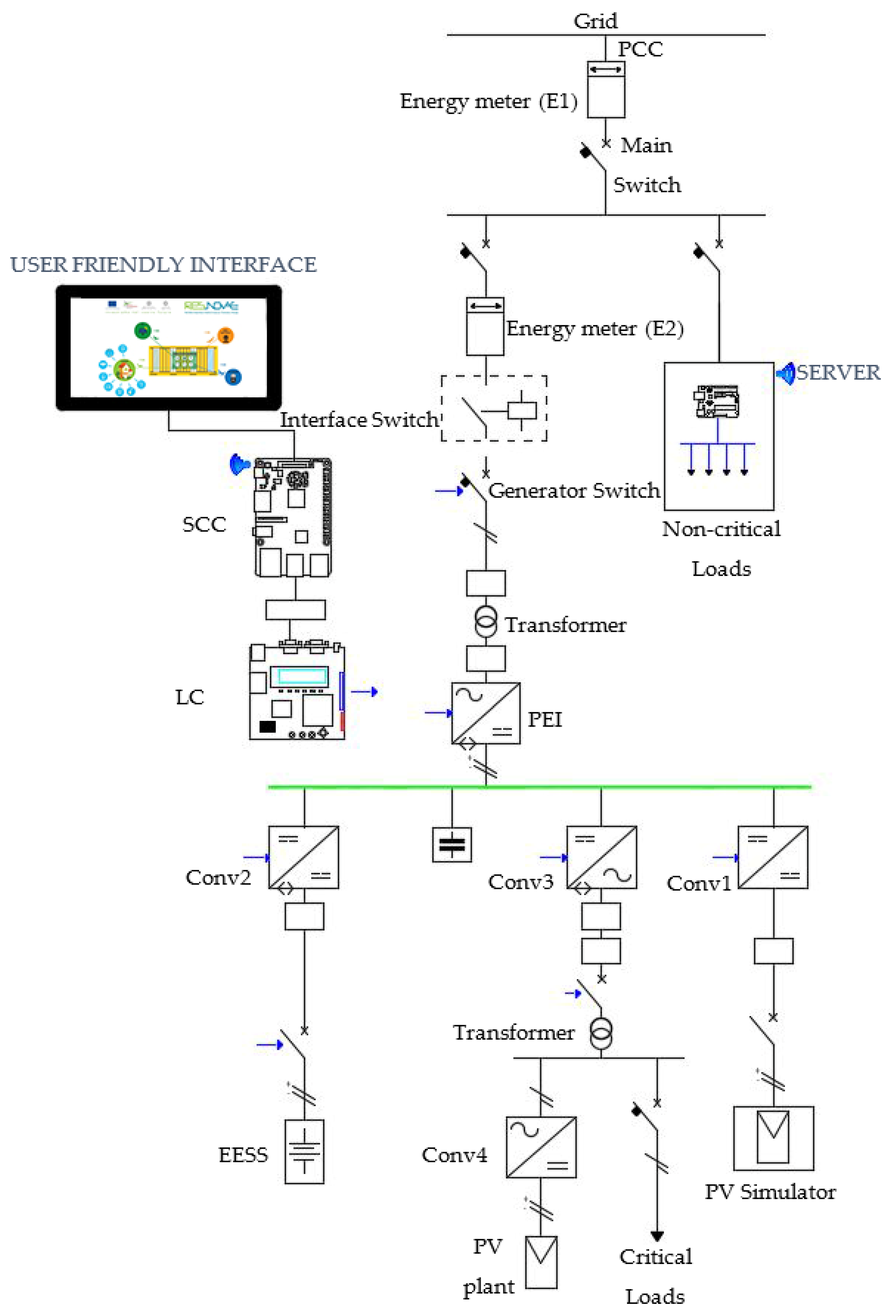
3. The SUN Configuration
- The electrical loads that need DC power supply are widely spread out;
- A DC distribution allows to reduce the conversion losses as well as a reduction of the voltage drop and a greater exploitation of the power leads;
- The micro DERs usually used (such as photovoltaic systems, wind turbines, fuel cells, etc.) produce electricity energy directly in DC or are equipped with an AC/DC power converter as a conversion stage for the decoupling of the source and then a second stage DC/AC power converter for connection to the grid; with a DC distribution the second conversion stage can be avoided;
- A DC distribution system ensures greater operational simplicity and above all greater safety and stability in case of operation in an intentional island configuration;
- A DC distribution system allows a very accurate control of power quality to which users are very sensitive; these users can be powered by an Uninterruptible Power Supply (UPS), a dedicated DC/AC power converter.
- To facilitate interconnection among different micro-energy sources from renewables and to make them more reliable and efficient;
- To easily manage different power flow;
- To compensate for load and production variations;
- To guarantee the continuity and quality of supply of critical loads, both in grid-connected and in stand-alone configuration;
- To maximize the use of renewable energy sources: Minimizing the exchange with the grid in grid-connected configuration and guaranteeing the supply of the critical loads in stand-alone configuration.
4. The SUN control
- SUN Central Controller (SCC);
- Local Controller (LC).
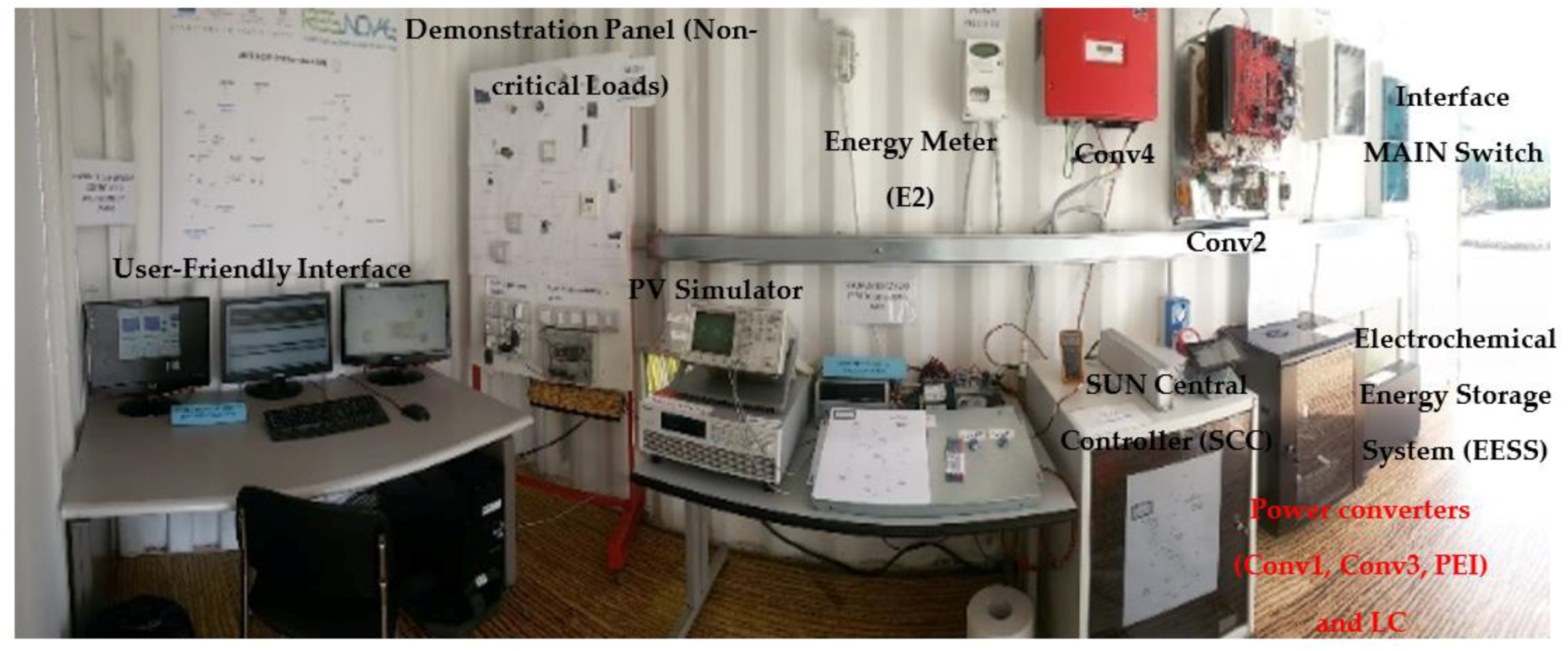
5. The SUN Installed at the Pilot Site
- Conv1: One boost DC-DC converter that performs the function of the Maximum Power Point Tracker (MPPT) and connects the PV simulator to the DC bus with a nominal power of 1 kW;
- Conv2: One half-bridge DC-DC converter that connects the electrochemical energy storage system to the DC bus with a nominal power of 1 kW;
- Conv3: One bi-directional DC/AC converter to supply the critical loads and to interface the PV standard DC/AC converter to the DC bus with a nominal power of 1 kW;
- PEI: The bidirectional DC/AC converter that operates as PEI with a nominal power of 1 kW.
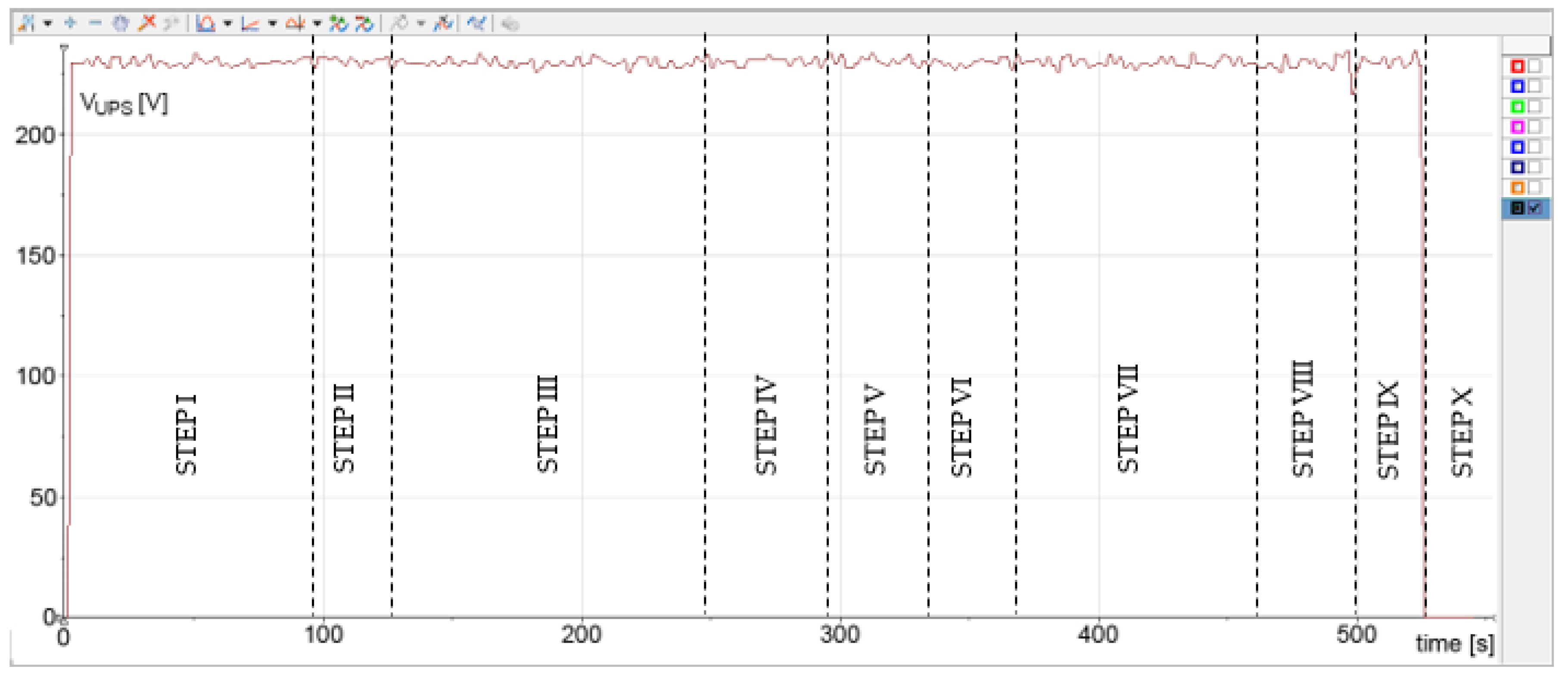
6. The Experimental Results
7. Conclusions
Author Contributions
Funding
Conflicts of Interest
References
- Dias-Sardinha, I.; Reijnders, L. Environmental performance evaluation and sustainability performance evaluation of organizations: An evolutionary framework. Corp. Soc. Responsib. Environ. Manag. 2001, 8, 71–79. [Google Scholar] [CrossRef]
- Parhizi, S.; Lotfi, H.; Khodaei, A.; Bahramirad, S. State of the art in research on microgrids: A review. IEEE Access 2015, 3, 890–925. [Google Scholar] [CrossRef]
- Ganesan, S.; Padmanaban, S.; Varadarajan, R.; Subramaniam, U.; Mihet-Popa, L. Study and Analysis of an Intelligent Microgrid Energy Management Solution with Distributed Energy Sources. Energies 2017, 10, 1419. [Google Scholar] [CrossRef]
- Barone, G.; Brusco, G.; Burgio, A.; Menniti, D.; Pinnarelli, A.; Sorrentino, N. A power management and control strategy with grid-ancillary services for a microgrid based on DC Bus. Int. Rev. Electr. Eng. 2014, 9, 792–802. [Google Scholar]
- Porsinger, T.; Janik, P.; Leonowicz, Z.; Gono, R. Modelling and optimization in microgrids. Energies 2017, 10, 523. [Google Scholar] [CrossRef]
- Brusco, G.; Burgio, A.; Menniti, D.; Pinnarelli, A.; Sorrentino, N. Energy management system for an energy district with demand response availability. IEEE Trans. Smart Grid 2014, 5, 2385–2393. [Google Scholar] [CrossRef]
- Barone, G.; Brusco, G.; Burgio, A.; Certo, F.; Menniti, D.; Pinnarelli, A.; Sorrentino, N. A local real-time controller to face the problem of power imbalance in a VED consisting of several DC Microgrids. In Proceedings of the 2016 IEEE 16th International Conference on Environment and Electrical Engineering (EEEIC), Florence, Italy, 7–10 June 2016; pp. 1–6. [Google Scholar]
- Rahmani-Andebili, M. Chapter 9: Cooperative Distributed Energy Scheduling in Microgrids. In Electric Distribution Network Management and Control; Springer: Singapore, 2018; pp. 235–254. [Google Scholar]
- Olivares, D.E.; Mehrizi-Sani, A.; Etemadi, A.H.; Cañizares, C.A.; Iravani, R.; Kazerani, M.; Jimenez-Estevez, G.A. Trends in microgrid control. IEEE Trans. Smart Grid 2014, 5, 1905–1919. [Google Scholar] [CrossRef]
- Chen, D.; Xu, L.; Yao, L. DC voltage variation based autonomous control of DC microgrids. IEEE Trans. Power Deliv. 2013, 28, 637–648. [Google Scholar] [CrossRef]
- Agustoni, A.; Borioli, E.; Brenna, M.; Simioli, G.; Tironi, E.; Ubezio, G. LV DC distribution network with distributed energy resources: Analysis of possible structures. In Proceedings of the 18th International Conference and Exhibition on Electricity Distribution, CIRED, Turin, Italy, 6–9 June 2005; pp. 1–5. [Google Scholar]
- Baek, J.; Choi, W.; Chae, S. Distributed Control Strategy for Autonomous Operation of Hybrid AC/DC Microgrid. Energies 2017, 10, 373. [Google Scholar] [CrossRef]
- Kurohane, K.; Senjyu, T.; Uehara, A.; Yona, A.; Funabashi, T.; Kim, C.H. A hybrid smart AC/DC power system. In Proceedings of the 5th IEEE Conference on Industrial Electronics and Applications, Taichung, China, 15–17 June 2010; pp. 764–769. [Google Scholar]
- Lee, W.P.; Choi, J.Y.; Won, D.J. Coordination Strategy for Optimal Scheduling of Multiple Microgrids Based on Hierarchical System. Energies 2017, 10, 1336. [Google Scholar] [CrossRef]
- Guerrero, J.M.; Vasquez, J.C.; Matas, J.; De Vicuña, L.G.; Castilla, M. Hierarchical control of droop-controlled AC and DC microgrids—A general approach toward standardization. IEEE Trans. Ind. Electron. 2011, 58, 158–172. [Google Scholar] [CrossRef]
- Lee, S.W.; Cho, B.H. Master–Slave Based Hierarchical Control for a Small Power DC-Distributed Microgrid System with a Storage Device. Energies 2016, 9, 880. [Google Scholar] [CrossRef]
- Guerrero, J.M.; Chandorkar, M.; Lee, T.L.; Loh, P.C. Advanced control architectures for intelligent microgrids—Part I: Decentralized and hierarchical control. IEEE Trans. Ind. Electron. 2013, 60, 1254–1262. [Google Scholar] [CrossRef]
- Abrishambaf, O.; Faria, P.; Gomes, L.; Spínola, J.; Vale, Z.; Corchado, J.M. Implementation of a Real-Time Microgrid Simulation Platform Based on Centralized and Distributed Management. Energies 2017, 10, 806. [Google Scholar] [CrossRef]
- Salas-Puente, R.; Marzal, S.; González-Medina, R.; Figueres, E.; Garcera, G. Experimental Study of a Centralized Control Strategy of a DC Microgrid Working in Grid Connected Mode. Energies 2017, 10, 1627. [Google Scholar] [CrossRef]
- Gao, L.; Liu, Y.; Ren, H.; Guerrero, J.M. A DC Microgrid Coordinated Control Strategy Based on Integrator Current-Sharing. Energies 2017, 10, 1116. [Google Scholar] [CrossRef]
- Li, D.; Zhao, B.; Wu, Z.; Zhang, X.; Zhang, L. An Improved Droop Control Strategy for Low-Voltage Microgrids Based on Distributed Secondary Power Optimization Control. Energies 2017, 10, 1347. [Google Scholar] [CrossRef]
- Lee, S.J.; Choi, J.Y.; Lee, H.J.; Won, D.J. Distributed Coordination Control Strategy for a Multi-Microgrid Based on a Consensus Algorithm. Energies 2017, 10, 1017. [Google Scholar] [CrossRef]
- Guerrero, J.M.; Loh, P.C.; Lee, T.L.; Chandorkar, M. Advanced control architectures for intelligent microgrids—Part II: Power quality, energy storage, and AC/DC microgrids. IEEE Trans. Ind. Electron. 2013, 60, 1263–1270. [Google Scholar] [CrossRef]
- Hwang, C.S.; Kim, E.S.; Kim, Y.S. A decentralized control method for distributed generations in an islanded dc microgrid considering voltage drop compensation and durable state of charge. Energies 2016, 9, 1070. [Google Scholar] [CrossRef]
- Soares, J.; Borges, N.; Vale, Z.; Oliveira, P.B. Enhanced Multi-Objective Energy Optimization by a Signaling Method. Energies 2016, 9, 807. [Google Scholar] [CrossRef]
- Baran, M.E.; Mahajan, N.R. DC distribution for industrial systems: Opportunities and challenges. IEEE Trans. Ind. Appl. 2003, 39, 1596–1601. [Google Scholar] [CrossRef]
- Brenna, M.; Bulac, C.; Lazaroiu, G.C.; Superti-Furga, G.; Tironi, E. DC power delivery in distributed generation systems. In Proceedings of the 13th IEEE International Conference on Harmonics and Quality of Power, Wollongong, Australia, 28 September–1 October 2008; pp. 1–6. [Google Scholar]
- Kwasinski, A. Quantitative evaluation of DC microgrids availability: Effects of system architecture and converter topology design choices. IEEE Trans. Power Electron. 2011, 26, 835–851. [Google Scholar] [CrossRef]
- Loh, P.C.; Li, D.; Chai, Y.K.; Blaabjerg, F. Autonomous operation of hybrid microgrid with AC and DC subgrids. IEEE Trans. Power Electron. 2013, 28, 2214–2223. [Google Scholar] [CrossRef]
- Justo, J.J.; Mwasilu, F.; Lee, J.; Jung, J.W. AC-microgrids versus DC-microgrids with distributed energy resources: A review. Renew. Sustain. Energy Rev. 2013, 24, 387–405. [Google Scholar] [CrossRef]
- Dou, C.-X.; Liu, B. Multi-agent based hierarchical hybrid control for smart microgrid. IEEE Trans. Smart Grid 2013, 4, 771–778. [Google Scholar] [CrossRef]
- Zheng, G.; Li, N. Multi-agent based control system for multi microgrids. In Proceedings of the 2010 International Conference on Computational Intelligence and Software Engineering, Wuhan, China, 10–12 December 2010; pp. 1–4. [Google Scholar]
- Colson, C.M.; Nehrir, M.H. Algorithms for distributed decision making for multi-agent microgrid power management. In Proceedings of the IEEE Power and Energy Society General Meeting, Detroit, MI, USA, 24–29 July 2011; pp. 1–8. [Google Scholar]
- Colson, C.M.; Nehrir, M.H. Comprehensive real-time microgrid power management and control with distributed agents. IEEE Trans. Smart Grid 2013, 4, 617–627. [Google Scholar] [CrossRef]
- Rahmani-Andebili, M.; Shen, H. Energy scheduling for a smart home applying stochastic model predictive control. In Proceedings of the IEEE 25th International Conference on Computer Communication and Networks (ICCCN), Waikoloa, HI, USA, 1–4 August 2016; pp. 1–6. [Google Scholar]
- Rahmani-Andebili, M.; Shen, H. Cooperative distributed energy scheduling for smart homes applying stochastic model predictive control. In Proceedings of the IEEE International Conference on Communications (ICC), Paris, France, 21–25 May 2017; pp. 1–6. [Google Scholar]
- Simoes, M. Intelligent based hierarchical control power electronics for distributed generation systems. In Proceedings of the IEEE Power Engineering Society General Meeting, Montreal, QC, Canada, 18–22 June 2006; pp. 1–7. [Google Scholar]
- Celli, G.; Pilo, F.; Pisano, G.; Soma, G.G. Optimal participation of a microgrid to the energy market with an intelligent EMS. In Proceedings of the 7th International Power Engineering Conference, Singapore, 29 November–2 December 2005; Volume 2, pp. 663–668. [Google Scholar]
- Xu, L.; Chen, D. Control and operation of a DC microgrid with variable generation and energy storage. IEEE Trans. Power Deliv. 2011, 26, 2513–2522. [Google Scholar] [CrossRef]
- Vandoorn, T.L.; Meersman, B.; Degroote, L.; Renders, B.; Vandevelde, L. A control strategy for islanded microgrids with dc-link voltage control. IEEE Trans. Power Deliv. 2011, 26, 703–713. [Google Scholar] [CrossRef]
- Vandoorn, T.L.; Meersman, B.; De Kooning, J.D.; Vandevelde, L. Analogy between conventional grid control and islanded microgrid control based on a global DC-link voltage droop. IEEE Trans. Power Deliv. 2012, 27, 1405–1414. [Google Scholar] [CrossRef]
- Wu, T.F.; Chang, C.H.; Lin, L.C.; Yu, G.R.; Chang, Y.R. DC-bus voltage control with a three-phase bidirectional inverter for DC distribution systems. IEEE Trans. Power Electron. 2013, 28, 1890–1899. [Google Scholar] [CrossRef]
- Lu, X.; Guerrero, J.M.; Sun, K.; Vasquez, J.C. An improved droop control method for dc microgrids based on low bandwidth communication with dc bus voltage restoration and enhanced current sharing accuracy. IEEE Trans. Power Electron. 2014, 29, 1800–1812. [Google Scholar] [CrossRef]
- Bryan, J.; Duke, R.; Round, S. Decentralized generator scheduling in a nanogrid using DC bus signaling. In Proceedings of the Power Engineering Society General Meeting, Denver, CO, USA, 6–10 June 2004; pp. 977–982. [Google Scholar]
- Schonbergerschonberger, J.; Duke, R.; Round, S.D. DC-bus signaling: A distributed control strategy for a hybrid renewable nanogrid. IEEE Trans. Ind. Electron. 2006, 53, 1453–1460. [Google Scholar] [CrossRef]
- Sun, X.; Lian, Z.; Wang, B.; Li, X. A hybrid renewable DC microgrid voltage control. In Proceedings of the IEEE 6th International Power Electronics and Motion Control Conference, IPEMC’09, Wuhan, China, 17–20 May 2009; pp. 725–729. [Google Scholar]
- Brenna, M.; Tironi, E.; Ubezio, G. Proposal of a local DC distribution network with distributed energy resources. In Proceedings of the IEEE 11th International Conference on Harmonics and Quality of Power, Lake Placid, NY, USA, 12–15 September 2004; pp. 397–402. [Google Scholar]
- Zhang, L.; Wu, T.; Xing, Y.; Sun, K.; Guerrero, J.M. Power control of DC microgrid using DC bus signaling. In Proceedings of the IEEE Twenty-Sixth Annual Applied Power Electronics Conference and Exposition (APEC), Fort Worth, TX, USA, 6–11 March 2011; pp. 1926–1932. [Google Scholar]
- Sun, K.; Zhang, L.; Xing, Y.; Guerrero, J.M. A distributed control strategy based on DC bus signaling for modular photovoltaic generation systems with battery energy storage. IEEE Trans. Power Electron. 2011, 26, 3032–3045. [Google Scholar] [CrossRef]
- Hwang, P.I.; Jang, G.; Pyo, G.C.; Han, B.M.; Moon, S.I.; Ahn, S.J. DC microgrid operational method for enhanced service reliability using DC bus signaling. J. Electr. Eng. Technol. 2015, 10, 452–464. [Google Scholar] [CrossRef]
- Dragičević, T.; Sučić, S.; Vasquez, J.C.; Guerrero, J.M. Flywheel-based distributed bus signalling strategy for the public fast charging station. IEEE Trans. Smart Grid 2014, 5, 2825–2835. [Google Scholar] [CrossRef]
- Eghtedarpour, N.; Farjah, E. Power control and management in a hybrid AC/DC microgrid. IEEE Trans. Smart Grid 2014, 5, 1494–1505. [Google Scholar] [CrossRef]
- Barone, G.; Brusco, G.; Burgio, A.; Menniti, D.; Pinnarelli, A.; Sorrentino, N. Intentional islanding control of a Smart User Network. In Proceedings of the 2015 IEEE 15th International Conference on Environment and Electrical Engineering (EEEIC), Rome, Italy, 10–13 June 2015; pp. 683–688. [Google Scholar]
- Belli, G.; Giordano, A.; Mastroianni, C.; Menniti, D.; Pinnarelli, A.; Scarcello, L.; Stillo, M. A unified model for the optimal management of electrical and thermal equipment of a prosumer in a DR environment. IEEE Trans. Smart Grid 2017. [Google Scholar] [CrossRef]
- Brusco, G.; Barone, G.; Burgio, A.; Menniti, D.; Pinnarelli, A.; Scarcello, L.; Sorrentino, N. A Smartbox as a low-cost home automation solution for prosumers with a battery storage system in a demand response program. In Proceedings of the 2016 IEEE 16th International Conference on Environment and Electrical Engineering (EEEIC), Florence, Italy, 7–10 June 2016; pp. 1–6. [Google Scholar]
- Barone, G.; Brusco, G.; Burgio, A.; Menniti, D.; Pinnarelli, A.; Sorrentino, N.; Motta, M. A Laboratory-Scale Prototype of a Smart User Network with DBS Control. Int. Rev. Electr. Eng. 2017, 12, 485–497. [Google Scholar]


| Power | Value | Description |
|---|---|---|
| PGrid | >0 | The SUN absorbs from the grid |
| =0 | The SUN not absorbs/injects from/into the grid or it is in stand-alone configuration | |
| <0 | The SUN injects into the grid | |
| PESS | >0 | The ESS charging |
| <0 | The ESS discharging | |
| PESS_max_charge, PESS_max_discharge | >0 | The ESS power maximum charge and the ESS power maximum discharge |
| PDG | >0 | The DG production is greater than zero |
| =0 | The DG production is equal to zero | |
| PLoad, PCritical_load | >0 | The loads absorb power |
| Components | Description | Parameters |
|---|---|---|
| Generator switch | Electromechanical contactor | 250V/50 Hz |
| Transformer | Transformer with transformation ratio of 1:1 | 230 V/50 Hz, 1 kVA |
| Grid Filter | Passive filter LCL type | L1 = 2.38 mH/6 A, C1 = 25 µF/500 V, R = 3 Ω/21 W, L2 = 0.77 mH/6 A |
| Load Filter | Passive filter LC type | L3 = 0.75 mH/6 A, C2 = 25 µF/500 V |
| Critical Load | Server | 1 kW-230 V/50 Hz |
| LC | ATMEL EVK1100 Evaluation kit with ATMEGA AT32UC3A microcontroller | 15 V/3.3 V-48 MHz-ADC 10 bit-PWM 15 kHz |
| SCC | Raspberry PI3 with Touch screen display 800 × 480 | 1.2 GHz 64-bit quad-core ARMv8 CPU, 802.11n Wireless LAN, 7″ |
| PV plant | Five polycrystalline solar panel, 250 W | 1.25 kWp |
| PV Simulator | Programmable DC power supply Chroma 62050H-600S | 600 V-8.5 A, 5 Kw-160 V-7.5 A, 1 kWp |
| EESS | FIAMM battery | 2 × 18 × 12 V = 2 × 216 V-9 Ah (around 3.9 kWh) |
| SCADA | Programmable Automation Controller (PAC) CompactRIO 9024–NI9114 FPGA–NI9229 ADC | 8 Ch-50 kS/s/Ch-24 bit |
| PEI | Bidirectional single- phase DC/AC full-bridge (IRAM136-3063B) | DC: 410 V-AC: 230 V/50 Hz 1 kW-PWM 15 kHz |
| Conv1 | Boost DC/DC converter | 160 V/410 V-PWM 16 kHz |
| Conv2 | half-bridge DC/DC converter | 216 V/410 V, 15 kHz |
| Conv3 | Bidirectional single- phase DC/AC full-bridge (IRAM136-3063B) | DC: 410 V-AC: 230 V/50 Hz 1 kW-PWM 15 kHz |
| Conv4 | Sunny Boy, SMA, DC/AC | 3 kW, 230 V, 50 Hz |
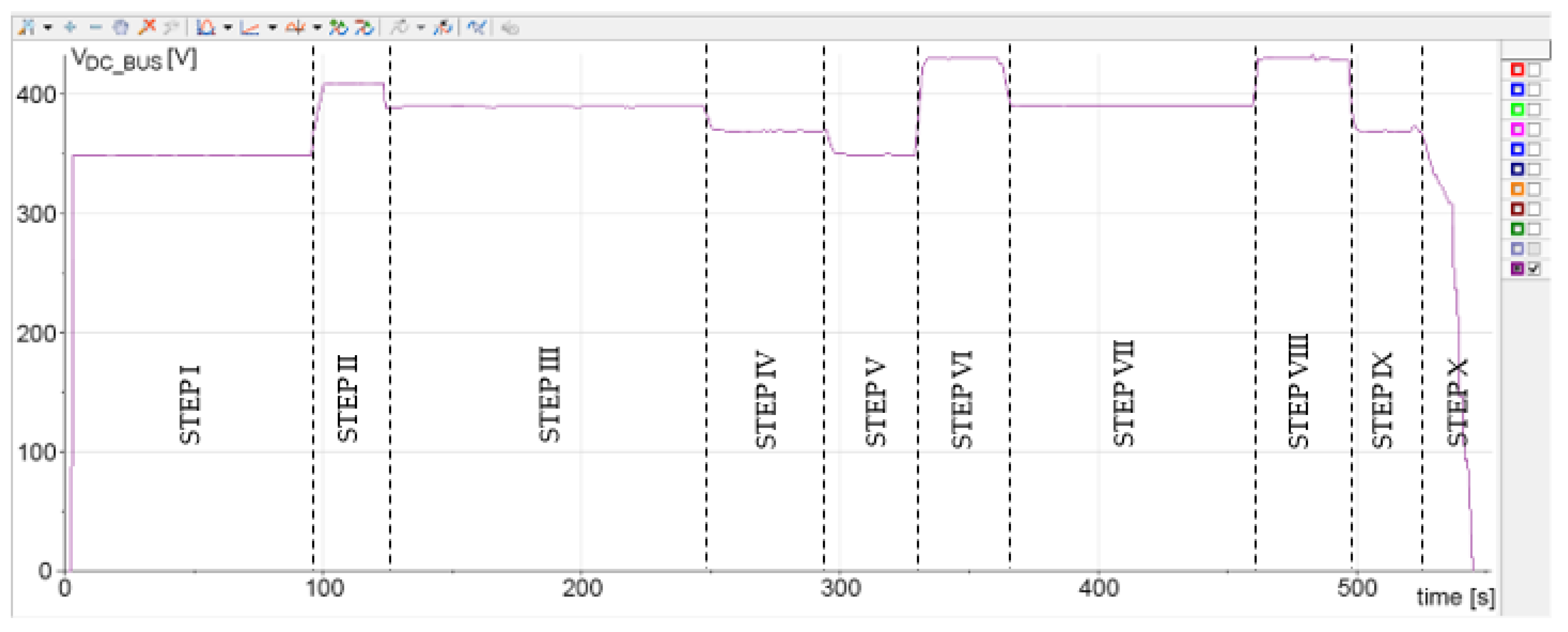
| VDC_BUS (V) | Mode | Operating Modes Description |
|---|---|---|
| 280 | Black-start | The PEI control is activated and operates as passive rectifier and all other converters are also activated |
| 350 | 5 | The PEI operates as master converter (rectifier configuration) and the EESS is discharging at maximum power |
| 370 | 4 | The half-bridge DC-DC converter (Conv2) of the EESS operates as master converter supplying the power deficit that is less than the maximum power supplied by the EESS |
| 390 | 3 | The half-bridge DC-DC converter (Conv2) of the EESS operates as master converter absorbing the power surplus that is less than the maximum power absorbed by the EESS |
| 410 | 2 | The PEI operates as master converter (inverter configuration) and the EESS is charging at maximum power |
| 430 | 1 | The PV boost DC-DC converter (Conv1) operates as master converter in constant voltage control (no MPPT) |
© 2018 by the authors. Licensee MDPI, Basel, Switzerland. This article is an open access article distributed under the terms and conditions of the Creative Commons Attribution (CC BY) license (http://creativecommons.org/licenses/by/4.0/).
Share and Cite
Barone, G.; Brusco, G.; Burgio, A.; Menniti, D.; Pinnarelli, A.; Motta, M.; Sorrentino, N.; Vizza, P. A Real-Life Application of a Smart User Network. Energies 2018, 11, 3504. https://doi.org/10.3390/en11123504
Barone G, Brusco G, Burgio A, Menniti D, Pinnarelli A, Motta M, Sorrentino N, Vizza P. A Real-Life Application of a Smart User Network. Energies. 2018; 11(12):3504. https://doi.org/10.3390/en11123504
Chicago/Turabian StyleBarone, Giuseppe, Giovanni Brusco, Alessandro Burgio, Daniele Menniti, Anna Pinnarelli, Michele Motta, Nicola Sorrentino, and Pasquale Vizza. 2018. "A Real-Life Application of a Smart User Network" Energies 11, no. 12: 3504. https://doi.org/10.3390/en11123504
APA StyleBarone, G., Brusco, G., Burgio, A., Menniti, D., Pinnarelli, A., Motta, M., Sorrentino, N., & Vizza, P. (2018). A Real-Life Application of a Smart User Network. Energies, 11(12), 3504. https://doi.org/10.3390/en11123504