1. Introduction
Energy generation from renewable sources has gained much attention in the last decade due to the drastic reduction of conventional energy sources from year to year and the rapid climate change primarily related to global warming. Among renewable energy sources, energy production from wind has been especially intensified. Concerning its growth trend, it is estimated that the installed capacity up to 2020 will reach almost 1300 TW world-wide [
1,
2]. Due not only to the facts that energy production using wind is recognized as environmentally friendly and is probably the most effective solution among renewable energy sources, but also due to the technological improvements achieved recently, WT systems have been brought into focus. The latest achievements are mainly focused on the development of optimal offshore solutions due to the higher potential for wind energy conversion at offshore sites in comparison with onshore installments. Offshore installments entail completely different challenges taking into consideration the difficult access to offshore sites and more complex hydrodynamical and aerodynamic loading profiles [
3]. It additionally faces the problems of energy transmission (laying cables under the sea), platform design, and similar problems. However, the larger abundance and greater strength of the wind at sea compared with onshore installments are sufficient reasons to investigate the possibilities of surmounting the existing shortcomings of offshore WT systems.
Further notable improvements are the development of advanced materials used for WT fabrication or even the development of smart multi-functional structures adopting continuous Structural Health Monitoring (SHM); for instance, smart sensor and actuator grids integrated in composite structures, reinforced steel structures (nacelle), advanced data transmission facilities, and others, as mentioned in [
4]. Most attention according to a number of existing publications is given to composite materials’ testing and the examination of the impacts of different fabrication methodologies on the feasibility of using composites (related to changes in strength and stiffness) [
5,
6,
7,
8]. As composite materials are mainly used for WT rotor blades’ fabrication and these are simultaneously the most susceptible to failure due to their direct exposure to the load, the integration of embedded sensing networks to enable continuous tracking of the state-of-health of composites is a reasonable strategy. Structural health monitoring systems implemented in such a way provide higher reliability of the system. Here, the information about the state-of-health can be used to make decisions about appropriate actions. Along with smart sensor network integration, the integration of in situ power sources in the composites has been discussed in some contributions [
9,
10,
11]. Even the loading profiles (wind speed and wind direction) are variable, so power provided to the grid has to fulfill dynamic requirements [
12]. To enhance the flexibility of the entire grid, integrated in situ power sources can be used to compensate lower energy production during low wind speed periods while recharging energy sources during periods of greater availability of wind. Embedding lithium-ion batteries into Carbon Fiber-Reinforced Polymers (CFRP) was proposed by Ladpli et al. [
9], whereas the integration of supercapacitors in CFRP was proposed by Shirshova et al. [
10]. Additional power sources utilizable for these purposes were reviewed and given in [
11,
13], each of them relating to different energy capacities and densities. Moreover, power generation using wind is currently more often discussed concerning wind farms, rather than individual WT systems. This additionally includes mutual relationships between individual WT systems on wind farms. It can be concluded from [
4] that the benefits of smart structures are closely related to efficient SHM of WT components, at the same time making the decision about a suitable response to changing inflow conditions possible. A suitable response in this case may include the control of vibration, damping, stress distribution, and similar responses.
Regardless of the location where the WT system is installed, fluctuating structural loads that induce mechanical stress on the wind turbine to a lesser or greater extent affect the system’s reliability. Due to the induced mechanical stresses, wind turbine systems and the systems’ components undergo gradual degradation over time, which is related to the decreased reliability of the system. To guarantee the reliability of the WT system, reducing the asymmetric structural loads on WT blades can be considered. Through the reduction of structural loads, the predefined service lifetime by the manufacturer of the wind turbine can be extended [
14].
A number of control strategies taking into consideration the mitigation of structural loads have been proposed [
15,
16,
17,
18,
19,
20,
21,
22]. In [
15], the aforementioned structural loads on rotor blades were mitigated using a nonlinear Individual Pitch Control (IPC). The controller proposed in [
15] consists of a “blade vibration damper and a pitch angle lead compensator” [
15]. The vibration damper mitigates the blade vibrations, whilst the angle lead compensator compensates for the delay between the desired/commanded and the real pitch angle. Similarly, Houtzager et al. [
16] introduced improvements to IPC by using the so-called lifted repetitive controller. The lifted repetitive controller is designed with the aim to reject load disturbances on rotor blades, leading to the reduction of structural loads and simultaneously extending the service lifetime. The results presented in [
16] proved that the lifted repetitive-based control reduced the vibrations on the structure to a great extent. The use of IPC for load reduction was proposed also in [
17,
18]. Combined pitch and trailing edge flap control for load mitigation was proposed in [
18]. The proposed control strategy included an individual pitch control loop and a trailing edge flap control loop, whereas the IPC control loop was used to mitigate the low frequency loads and the trailing edge flap control loop to mitigate the high frequency loads [
18]. The control strategy proposed in [
19] consisted of an optimal multivariable Linear Quadratic Gaussian (LQG) controller and a feedforward disturbance rejection controller with inaccessible wind turbine states estimated using a Kalman filter. The main objective of the LQG controller is the minimization of rotor tilt and yaw moments. The approach was tested and compared with the conventional IPC method “in simulation studies with models of different complexities” [
19]. In [
20], a set of collective and individual pitch control algorithms was proposed, whereas the control algorithms were LQR control algorithms with Integral action (LQRI) utilizing Kalman filters to estimate system states. The proposed control algorithms [
20] controlled rotor speed and blade bending moments at the same time. Based on the simulation results, acceptable rotor speed regulation and significant reduction of blade bending moments were achieved. Hence, a linear-quadratic regulator-based individual pitch controller aiming to reduce structural loads of wind turbines was proposed in [
21].
Beside IPC, a nonlinear Model Predictive Controller (MPC) considering wind predictions was proposed for the reduction of structural loads on the WT tower and blades [
23]. The information from Laser Induced Differential Absorption Radar (LIDAR) systems was used to predict wind disturbances at the front of wind turbines, which were further integrated into the control. According to [
23], the use of wind predictions in this sense contributes to the mitigation of structural loads by up to 30% with almost no impact on energy production and additionally limits the pitch rates. The reduction of structural loads in the aforementioned case was achieved through the mitigation of inflow transients (gusts), which were understood as unknown disturbances to MPC. Such an implementation does not guarantee the predefined service lifetime of WT. In [
23], Damage Equivalent Load (DEL) was calculated, but not integrated into the control as an online implementation of DEL calculation was not carried out. The analysis was based on a comparison of a baseline controller and MPC controller with integrated wind predictions, whereas the decrease in DEL was noticeable. Similarly, MPC was proposed in [
24] to minimize the damage accumulating in the system. Improved MPC, namely a scheduled model predictive controller able to control MIMO systems with multiple control objectives, was proposed in [
25]. This approach allows the introduction of system input constraints, as well as adjusting to the aerodynamic nonlinearities [
25].
Active load control of wind turbine tower structural loads using the disturbance accommodating control was proposed in [
26]. State-space control here was introduced to consider the coupled wind turbine dynamics. The disturbance accommodating control technique was applied to cancel the effect of wind disturbances. In a similar manner, disturbance tracking control was applied to the design of a torque controller, which optimized the energy capture under the influence of “persistent wind disturbances” [
27]. In both aforementioned contributions, the mitigation of blade bending moments was reported. Disturbance accommodating-based control was also used in [
28] to regulate rotor speed at above-rated wind speeds, mitigating at the same time cyclic blade root loads. Similarly, a parameterized disturbance observer-based controller with an individual pitch control strategy was designed in [
29] to reduce cyclic loads generated due to wind shear and tower shadow effects. The proposed controller was able to reduce “output power fluctuation, tower oscillation and drive-train torsion” [
29]. An approach to estimate the fatigue loads based on the reconstruction of data series of the stochastic properties measured at wind turbines was discussed in [
30,
31]. The authors here proved the possibility of accurate estimation of fatigue loads in any wind turbine on a wind farm using “only the load measurements at one single turbine and the set of wind speed measurements” [
30]. For these purposes, a stochastic differential equation describing the evolution of the torque for one wind turbine driven by the wind speed was derived and used for the prediction of fatigue loads [
30].
Structural loads on WT rotor blades can be reduced by appropriate WT blade design, as proposed in [
32]. In accordance with this, improvements primarily in rotor blade geometry and airfoil properties ultimately affect annual energy production, the overall mass of WT, as well as WT thrust/structural loads. These three parameters are considered for optimization. It is shown that changes introduced to WT rotor blades (blade thickness, changes in chord, airfoil geometry) have a high impact on the overall performance of the WT system [
32].
Although structural load mitigation of WT was discussed and achieved using different approaches in the mentioned contributions, the lack of solutions that include the information about the current state-of-health of WT and precisely-defined levels of the load that needs to be mitigated to achieve the predefined service lifetime is noticeable.
In this contribution, the evaluation of fatigue loads, targeted at integrating the knowledge about accumulated damage in the control strategy to mitigate structural loads, is given. Contrary to the aforementioned contributions, different easy to design and implement LQR-based IPC controllers and a suitable control selection module are used to achieve integration with the online estimated state-of-health and to guarantee the predefined service lifetime. The controller parameters are changed depending on the actual degradation state of WT rotor blades.
3. Controller Design
It is important to emphasize that the model of WT is provided by NREL. For controller design, it is important to determine which inputs and outputs are of high importance in terms of controller objectives and load mitigation. Simulation parameters, as well as the wind profile used for simulation are transferred to the model through configuration files provided by NREL, whereas also, the sampling rate is defined. Determined inputs and outputs in this case are closely related to enabled DoFs, which are explained in detail in
Section 2.1 and shown in
Figure 2.
Five controllers are designed, affecting structural loads to a greater or lesser extent depending on the loading profile and accompanying damage increments, whilst generator power and rotor speed have to be maintained as close as possible to the desired values. To provide the control of generator power and rotor speed, a baseline PI controller is used, but is not further elaborated here. Additionally, individual blade pitch (IPC) controllers are proposed for the reduction of flap-wise rotor blade bending moments [
35]. Individual blade pitch controllers are designed as LQR-based controllers. As introduced in detail in [
35], the objective function to be minimized is expressed as:
where
u is the control input and
x denotes the system state variable, while
Q and
R are the state and control weighting matrices, respectively. Here,
Q optimizes the trade-off between power/speed regulation and structural load reduction. On the other hand,
R is used to penalize the control efforts.
The tuning of controllers includes the selection of suitable
Q and
R matrices corresponding to different levels of structural load reduction. Not all system states are directly accessible, implying the utilization of the Kalman filter to estimate the inaccessible system states. The linearized model introduced in
Section 2.1 is used to design the controllers. The complete control scheme with integrated fatigue load examination is depicted in
Figure 2. Inputs to the control module according to
Figure 2 are, besides measured or estimated system variables, estimated damage increments or accumulated damage over time (depending on the considered case).
4. Simulation Results
The results obtained under the usage of the fatigue damage evaluation model along with controller selection based on information about the damage accumulated over the service lifetime are depicted in
Figure 3 and
Figure 4. Similarly, the results obtained using controller selection based solely on information about damage increments are given in
Figure 5 and
Figure 6.
In the upper diagrams of
Figure 3,
Figure 4,
Figure 5 and
Figure 6, wind speed at hub height, serving as one input to the wind turbine model, is given beside the controller outputs. Relevant system variables to be monitored are the generator power and rotor rotational speed. Here, no significant impact on generator power and rotor rotational speed was noticeable as the sacrifice of generator power/rotor rotational speed has to be in acceptable limits. Besides these two system variables, the root bending moment of Blade #1, fore-aft bending moment of the tower, as well as the accumulated damage are depicted in the lower diagrams in
Figure 3 and
Figure 5. Additionally, the effect of the adopted control strategy on the tower side-to-side bending moment, as well as high-speed shaft torque is illustrated in
Figure 4 and
Figure 6. The accumulated damage and accompanying damage increments (for the case where controller selection is done solely based on tracking damage increments) are given in
Figure 3 and
Figure 5. Controller #1 is the controller that provides the lowest impact on structural load reduction, whilst Controller #5 is that with the highest one.
Discussion about the Results Obtained
At first glance, it can be noticed that the level of flap-wise bending moment reduction (here, Blade #1) was much higher concerning controller selection based on accumulated damage than it was in the case when a particular controller was chosen based exclusively on information about the damage increments.
This result can be explained by the fact that in the case of controller selection based solely on the values of damage increments, the previously accumulated damage was not considered. Otherwise, it would be considered that the previous loading profile had no impact on damage accumulation and the consequent aging of system, but was still usable for the examination of structural loads in a short time framework. As such, the controller with the best performance regarding the reduction of structural loads was chosen only when the damage increment became very high. Accordingly, with the decrease of the damage increment, the controller with the worst performance according to the reduction of structural loads was chosen.
From another point of view, if values of damage increments were considered along with the overall damage accumulated in the system, then the controller with the best performance according to the reduction of structural loads was chosen as the system approached the end of its lifetime. This means that the highest level of the reduction of structural loads was achieved shortly before the end of the lifetime, albeit at a slightly compromised speed/power production objective. This caused the selection of the controller to be carried out in a successive way, and the controller with a higher level of structural load reduction, once chosen, was never swapped with a controller providing a lower level of structural load reduction.
Moreover, the tower side-side bending moment, as well as tower fore-aft bending moments were slightly decreased, even if the controllers were not designed to consider the reduction of the bending moments of the tower. As depicted in
Figure 3 and
Figure 4, the generator power and generator rotational speed were in both cases slightly scarified; but to a lesser extent, so that the decrease in power production was still acceptable. It is worth emphasizing that the controller with the highest impact on structural load reduction (Controller #5) produced in general a higher deviation between the desired and actual power generation. Exactly this fact justifies the integration of fatigue load examination in the control module, so that the sacrifice of power generation is acceptable in the case that the RUL of its lifetime is decreased to a predefined level.
The results presented in
Section 4 are compliant with the desired optimization goal, which is the determination of the trade-off between energy production and WT reliability. As such, the proposed control strategy can be considered as efficient.
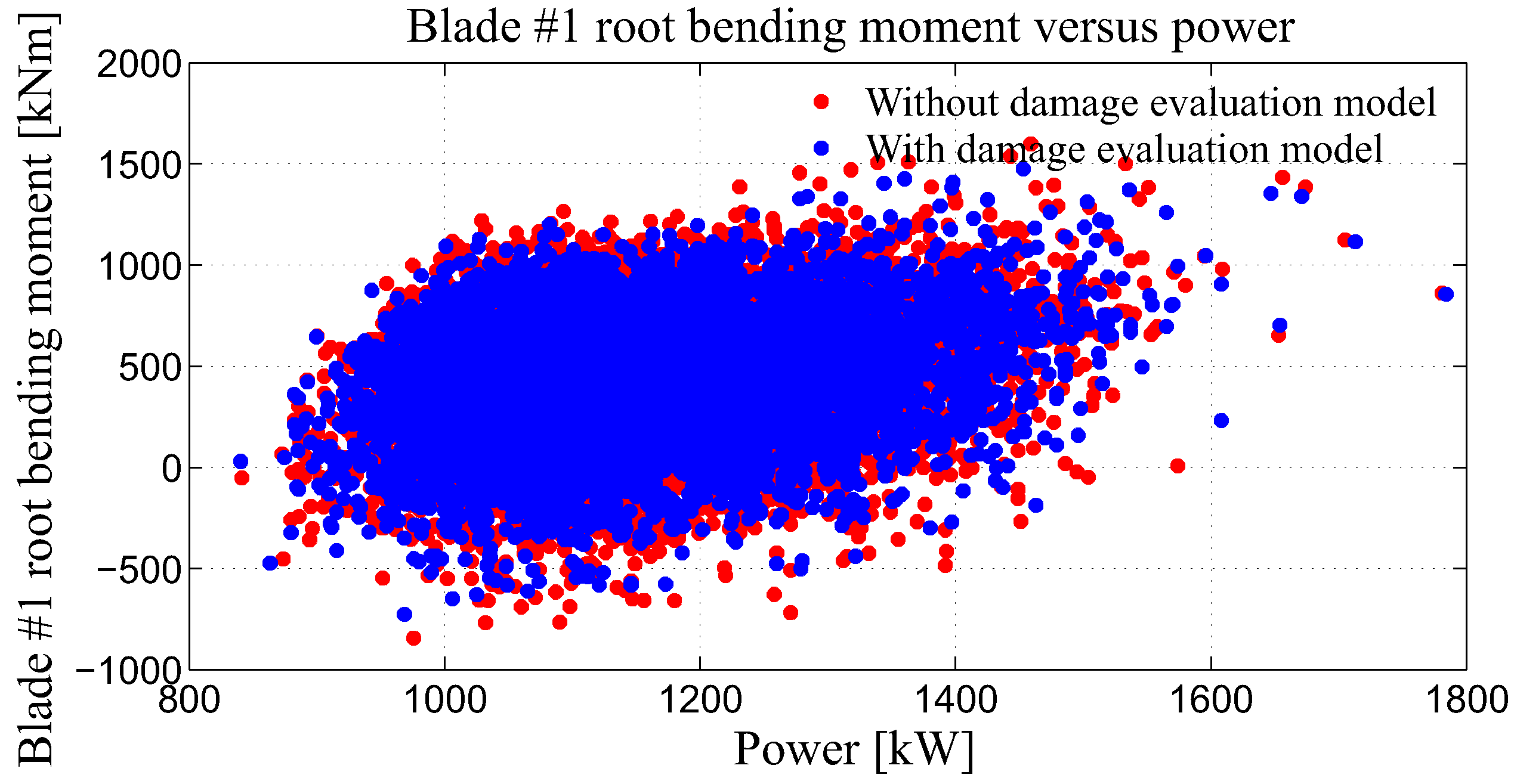
The resulting dependence and effects between rotor bending moment and generated power are depicted in
Figure 7 and
Figure 8. The dependence between High-Speed Shaft (HSS) torque and generated power is shown in
Figure 9 and
Figure 10.
The control results based on the use of the accumulated damage are depicted in
Figure 7 and
Figure 9, whilst the control results based on the actual resulting damage increments are shown in
Figure 8 and
Figure 10. Such a graphical illustration of the results obtained was used here to evaluate the performance of the newly-developed control strategy.
According to the results presented, a high impact on the flap-wise rotor blade bending moment was noticeable. The result of the implemented mechanism becomes clear in
Figure 7 and
Figure 8. The control reduced the number of outliers strongly affecting the lifetime, but the overall behavior was not effected. At the same time, the reduction of the high-speed shaft torque was much less. This implies that the reduction of structural loads on rotor blades did not have a high impact on HSS torque. This proves the capability of the proposed control strategy to reduce structural loads on WT blades without a significant impact on HSS torque. In addition, the standard deviation of generated power, HSS torque, and Blade #1 root bending moment are calculated and presented in
Table 1 to show not only qualitative, but also quantitative indicators.
All cases depicted in
Figure 8 and
Figure 9 were analyzed. Three cases are stated in
Table 1 as: (i) Case I, the model without structural load reduction consideration: the baseline PI controller; (ii) Case II, the model with the consideration of structural load reduction: controller selection based on accumulated damage; and (iii) Case III, the model with the consideration of structural load reduction: controller selection based on damage increments. However, the same conclusion was made, as the highest discrepancy in the standard deviation was obtained for bending moments, whilst the same did not change to a great extent for HSS torque and generated power.
5. Summary and Conclusions
In this contribution, a new control strategy for WT systems is introduced. The developed control strategy provides a trade-off between the mitigation of structural loads and the desired power production. By the evaluation of fatigue loads and the appropriate adoption of the control strategy according to the examined fatigue loads, it was intended to achieve the mitigation of structural loads. For this purpose, five different MIMO controllers corresponding to different levels of structural load reduction were designed. All MIMO controllers were LQR-based controllers, where the adjustment of the level of structural load reduction was obtained by appropriate selection of the Q and R matrices. Moreover, the usage of a number of MIMO controllers is equivalent to the usage of a single controller with adaptive controller parameters. The selection of a particular MIMO controller was conditioned by the actual value of damage accumulation or the damage increment, which were calculated using an appropriate fatigue damage evaluation model.
The results obtained prove that the proposed control strategy enabled the reduction of structural loads in combination with a slight compromise on the power generation. The mitigation of structural loads was analyzed using (i) successive controller selection, whereas the MIMO controller providing the highest level of structural load reduction corresponded to the highest values of accumulated damage, or (ii) damage increment-conditioned controller selection, whereas the MIMO controller providing the highest level of structural load reduction corresponded to the highest values of damage increments. In the case that the controller selection was carried out using accumulated damage, the reduction of structural loads was higher as the system was closer to its end of lifetime. On the contrary, in the case that the controller selection was conditioned by the tracking of damage increments, the reduction of structural loads had a short time span with a noticeable change of the structural loads.
This approach implicitly assumed that the damage between two subsequent load cycles stays constant. As this case rarely occurs in practice, the development of additional fatigue damage evaluation models can be investigated in the future to obtain a more accurate prediction of RUL. Besides the development of improved fatigue damage accumulation models, further improvements are still possible concerning the control strategy. These improvements may lead to an investigation of the possibilities to consider the mitigation of other structural loads of WT along with rotor blade structural loads, such as top-tower fore-aft and top-tower side-to-side tower structural loads.


