Article

Power-Split Hydrostatic Transmissions for Wind Energy Systems

Department of Mechanics Mathematics and Management (DMMM), Polytechnic University of Bari, Viale Japigia 182, 70126 Bari, Italy
*
Author to whom correspondence should be addressed.
Energies 2018, 11(12), 3369; https://doi.org/10.3390/en11123369
Submission received: 22 October 2018 / Revised: 22 November 2018 / Accepted: 28 November 2018 / Published: 1 December 2018
(This article belongs to the Section A: Sustainable Energy)

Abstract

:
In a wind turbine, if a continuously variable transmission is placed between the turbine rotor and the generator, the speed ratio can be tuned to match the variable rotor speed to the constant speed of the electric generator, thus eliminating the need to adapt the frequency to the grid. In this paper, power-split hydrostatic transmission (PS-HTS) architecture is proposed as a suitable continuously variable transmission for application to wind turbine systems. The performance of PS-HTS is modelled and compared with that of previously proposed architectures in which the hydrostatic transmission is placed in-line with traditional drives (in-line HTS). It is shown here that the PS-HTS can improve the annual energy production of a 250 kW rated power wind turbine of about 10–11% by employing a hydrostatic transmission with one-seventh the size of the one requested by in-line HTS architecture.

1. Introduction

Wind is the fastest growing and most widely used form of the emerging renewable energy technologies for the production of electricity [1]. Due to the numerous advances in wind generation technology, the potential for wind as a power source is immense. However, the conversion of wind energy into electric energy is particularly cumbersome due to the variability of wind speed. Wind turbine rotors achieve their maximum efficiency at a particular value of the tip-speed ratio [2]. A traditional wind power generation system requires a wind turbine rotor with blades, a gearbox, and a generator to harvest wind energy and produce electricity. Since the generator must rotate at a constant speed, the rotor must also rotate at a constant speed, even though the wind speed is not constant at all. To achieve this goal, the pitch angle of the blades is regulated in order to tune efficiency of the conversion of wind speed into torque, thus leading to the control of rotor velocity but, on the other hand, a reduction in the average efficiency of the generator. With the aim of increasing the efficiency of the wind turbines, variable speed systems are normally employed, which optimizes the rotor speed as a function of the wind speed [3,4]: In these systems, the turbine runs at a tip speed ratio that ensures the turbine has maximum efficiency over most of its working range. Further advantages in variable speed systems comes from the fact that the turbine can operate as a flywheel, smoothing the torque variations; they are less sensitive to the characteristics of the wind footprint of a given location; and they are quieter [3,5,6]. In currently developed variable speed turbines, an over gear is used to couple the turbine with an electric generator. The main electric generators used today are doubly-fed induction generators and converter drive synchronous generators [2,4]. A converter working at the same rated power is placed between the generator and the grid. In this architecture, the generator rotates with variable speed often far from its most efficient working points. In these systems, the strategies to capture the maximum amount of power are still under debate, as discussed in [7,8]. The development of novel, more reliable, and efficient wind turbine systems is of fundamental importance to optimize the wind energy recovery [9,10]. Khakpour et al. [11] and Hall et al. [12,13] investigated the performance that can be achieved by incorporating a mechanical variator with a discrete ratio into variable wind turbines. The effects of Continuously Variable Transmissions (CVT) placed between a wind turbine rotor and an electric generator (GEN) were examined in [14] and, in particular, in [15,16], and in [17], a belt/chain CVT and a half toroidal traction drive were considered, respectively. Finally, in [5], the speed ratio was varied continuously by means of a planetary gear coupled with an additional motor. In all of these cases, the variability of the speed ratio was demonstrated to bring benefits in terms of energy recovery, because the transmission can vary automatically the speed ratio, adapting the constant speed of the generator to any variation of the wind speed, thus allowing the generator to work at more efficient values. Further, the costs associated with the expensive power electronics are almost eliminated. Tuning the speed ratio between the rotor and the generator provides the opportunity to deliver power directly to the grid. The drawback of CVT is that it has a lower efficiency than the fixed ratio gearbox. Power split CVT transmissions (PS-CVT) are often employed to improve the performance of a CVT [18,19]. Their basic architecture includes a CVT and a planetary gear train (PG). The CT can be mechanical, electronic, or hydraulic. The literature is rich in studies on the efficiency of PS-CVTs [19,20,21], which have also been experimentally verified through test benches [22,23,24], or on the design of original typologies [25,26]. Depending on the particular design and characteristics of the CVT, these transmissions may lead to a power split path (type III flow, Reference [21]), in which the power bifurcates, partly going through the CVT and partly through the mechanical path (with a constant speed ratio), or recirculating power paths (type I and II, Ref. [21]) in which the power recirculates in such a way that sometimes the power through the CVT is larger than the total power delivered by the device. Mantriota [27] investigated the performance of variable speed wind turbines equipped with input split PS-CVT with a recirculating Type I power flow and an output split PS-CVT with Type III power flow. Both architectures allow the turbine to operate with maximum efficiency, and the generator produces electric power at a desired frequency. The results reported therein show that the maximum value of the ratio between the power across the CVT and the rated power of the turbine depends only on the speed ratio range r r of the CVT, defined as the maximum value divided by the minimum value of the speed ratio that the CVT transmission permits. In order to increase the efficiency of the PS-CVT, the amount of power crossing the CVT for given overall power delivered by the whole transmission should be as small as possible. In [27], it was shown that the output split configuration with Type III power flow is characterized by a maximum power ratio value of only 10%. This value is smaller than the 15% achieved with an input split transmission with Type I power flow; thus, the output split configuration is suggested to be the most convenient one to enhance the efficiency of the powertrain with a variable speed ratio [27]. The aforementioned architectures need a CVT with an infinitely large speed ratio range (i.e., Infinitely Variable Transmission, IVT). Recently some researchers have proposed the use of hydrostatic transmission [28,29] to maximize the turbine efficiency. A Hydraulic Transmission System (HTS) consists of a displacement pump driven by the prime-mover and one or more either fixed or variable-displacement motors. The pump converts the input mechanical energy into pressurized fluid, from which the potential energy is then delivered and distributed to the energy consumers. The motor(s) then convert the potential energy back into mechanical energy. The power transferred from the wind turbine to the generator is also important to feed the ancillary functions of the turbine [30,31]. Since HTS allows a neutral gear (speed ratio equal to zero), the speed ratio range of HTS is infinitely large; thus, such systems can be proficiently adopted in output split transmissions with high efficiency. This solution was also studied in [32], where the authors investigated control strategies to enhance the annual energy production of a wind turbine system by the prediction of the turbine reaction torque. In this paper, we follow a model based approach to investigate the performance of variable speed wind turbines equipped by two different powertrains. In the former, the tuning of the speed ratio is achieved by means of a power split HTS (PS-HTS); in the latter, it is achieved by HTS mounted in-line with the traditional part of the powertrain (in-line HTS). In this paper, the focus is on the efficiency of the hydraulic machines in real operation, which has somehow been neglected in previous research. The Annual Energy Production, related to a specific windmill site, for the same wind turbine equipped with the two different powertrains mentioned above is calculated and the comparison is discussed.

2. Wind Turbine and Power Split Hydraulic Transmission

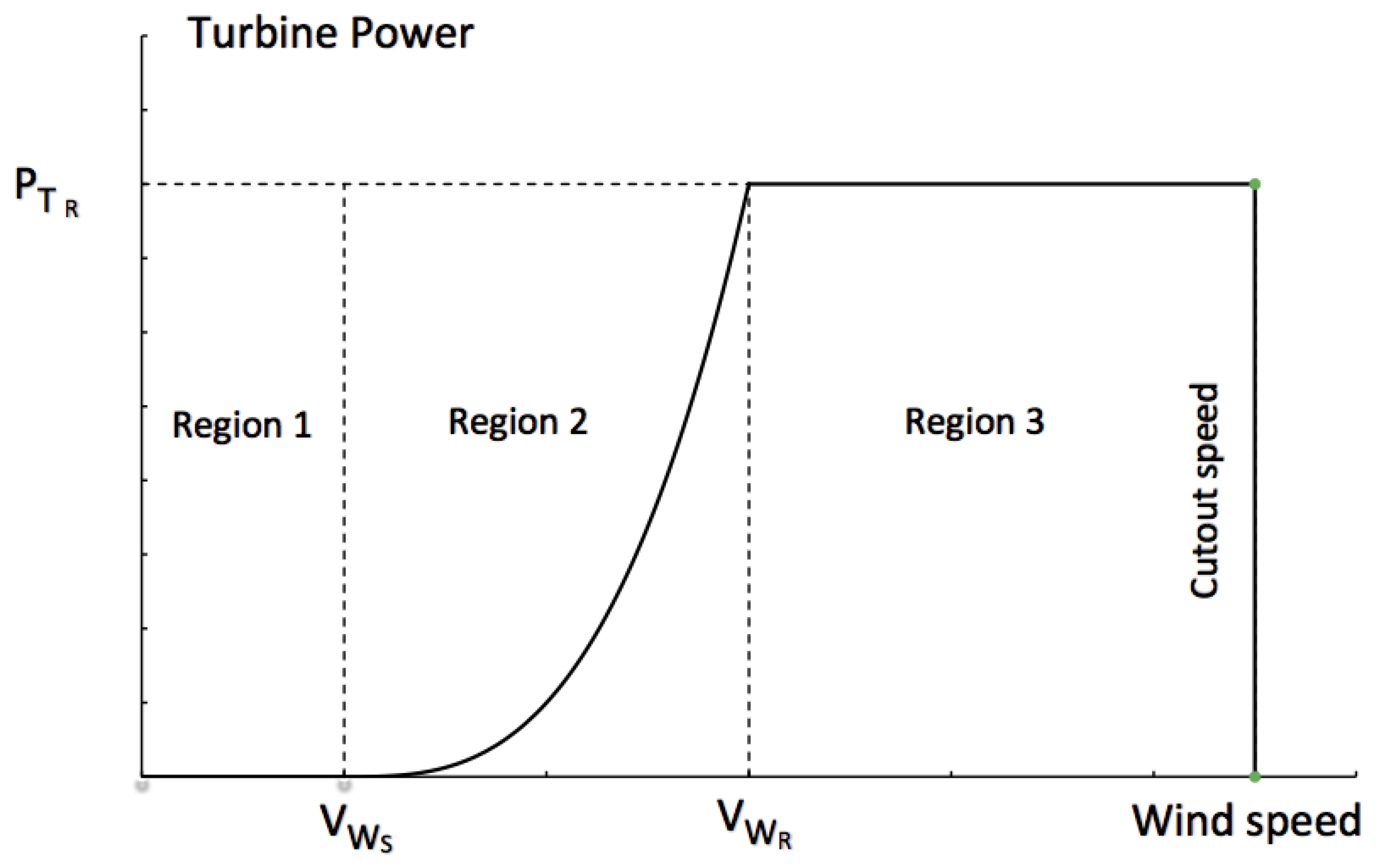
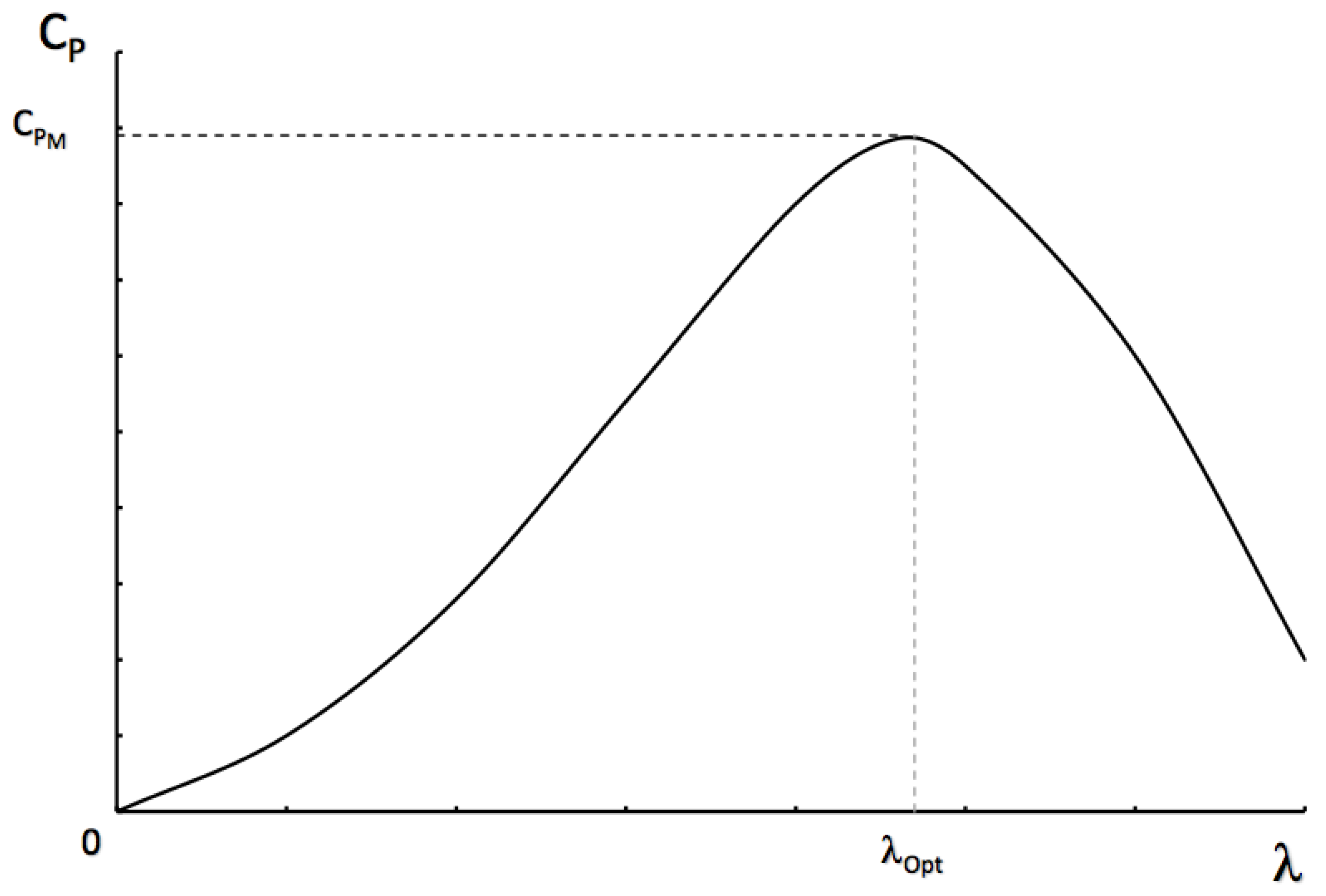
2.1. Wind Turbine System

There are typically three main operational regions for variable-speed wind turbines [1,33]. The operational regions of a variable-speed wind turbine are emphasized in Figure 1 where the turbine power is shown as a function of the wind speed V W . In the low-wind speed region (region 1), the rotor is still and the turbine is disconnected from the grid and it does not produce any power. The rotor starts rotating at the threshold value V W S to get into region 2. The boundary values of wind speed are the ones at which the turbine starts to operate V W S at the rated wind speed ( V W R ). At the rated wind speed, the turbine produces the rated power ( P T R ).
To achieve the goal of maximizing the power in region 2, the rotor speed is controlled in such a way that the characteristic power coefficient C P is maximized. When operating in region 3 the wind speed is high and the output power is maintained at a constant level that is equal to its maximum value, independently of the wind speed [1,33]. The control focus in this region is to prevent the output power exceeding the rated value. This prevents the system from power overloading and sustaining related damage. This control action can be realized by decreasing the power coefficient through the regulation of the blade pitch angle. If the wind speed exceeds the cut-out speed (Figure 1), the wind turbine is shut down. Optimal regulation of the turbine speed is necessary in region 2 where the turbine power is [2]
P T = 1 2 C P S ρ V W 3
in which ρ indicates the air density, C P is the power coefficient, and S is the wind turbine frontal area. The power coefficient is the function of a parameter commonly indicated as λ , which is defined as the peripheral speed u of the turbine rotor divided by the wind speed [2]:
λ = u V W = R ω T V W
where R is the turbine radius (blades) and ω T is the turbine angular velocity. In the case of a horizontal axis machine, the typical trend of the power coefficient C P is the one shown in Figure 2.
For each value V W of wind speed, the maximum turbine power is obtained if C P equals its maximum value C P M , which occurs when λ = λ O p t . Therefore, for optimal energy recovery, the turbine must always work at λ O p t . This means that (Equations (1) and (2))
P T = 1 2 C P M S ρ V W 3 = k 1 V W 3 = k 1 R λ O p t 3 ω T 3 = k 2 ω T 3
where P T and ω T are the optimal value of turbine power and related turbine velocity with wind speed V W ; k 1 and k 2 are constants. The electric machines commonly adopted for energy conversion and delivery to the electric mains are induction and synchronous electric generators [2,3]. The AC current frequency is a constraint for synchronous machines which must strictly rotate at a synchronous speed, whereas induction generators must work at slip values generally lower than 10% and at an angular speed greater than the synchronous speed. In this work, we assume a synchronous electric generator is connected directly to the mains (without an inverter device).

2.2. Hydraulic Transmission Systems (HTS)

HTS are exceptional power transmissions in the fields of manufacturing, automation, and heavy duty vehicles [34], when variable output velocity is required. They are characterized by high durability, quick response times, precise velocity regulation over a wide load range, and the ability to produce large forces at high speeds [35]. Today, the development of hybrid systems has a strong focus on electric solutions. This is due to the common feel that electric machines have higher efficiency than hydraulic machines and that electric power is cleaner and easier to control. The hydraulic machines must be more efficient, smaller, and lighter than most of the commonly used machines to compete with their electric equivalents. The commonly adopted axial piston machines with variable displacement are easy to control but their efficiency at small displacements is too small. For instance, the efficiency can drop by 90% to 73% for the in-line motors at a constant power of about 90 kW [36] when displacement is reduced. This characteristic is an obstacle to the making of an energy efficient hybrid system. New hydraulic machine concepts have been developed in recent years. Two of the most promising concepts are the earlier mentioned Digital Displacement pump/motor from Artemis, [35] and the Floating Cup machine from Innas [37]. The Digital Displacement machine is based on a smart arrangement of loaded bearings, which gives the lowest possible losses for the active cylinders. The efficiency is greater than 95% over a large loading range. The floating cup is reported to have high efficiency over a wide range of working conditions. The tested maximum efficiency is up to 97%. When operating at low speeds in combination with high loads, the hydro-mechanical losses are very small. These two machines are well adapted for hydraulic hybrid applications, where a large efficiency over a wide operating range is required to compete with other technologies. Also, the idling losses are small in these machines in comparison with common axial piston machines [38].

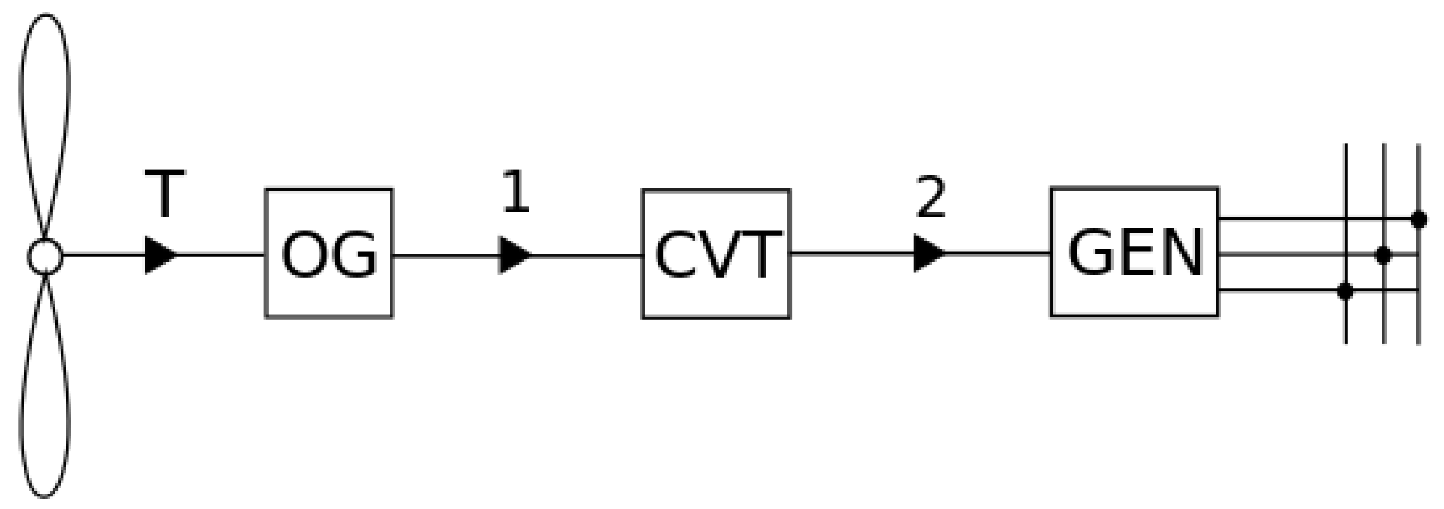
2.2.1. In-Line HTS Configuration

The energy balance equation of the in-line HTS architecture (Figure 3) can be derived straightforwardly. Recalling Equation (3), the input power of the powertrain is
P T = k 2 ω T 3
where k 2 = k 1 [ D / ( 2 λ O p t 3 ) ] 3 and k 1 = 0.5 C P M S ρ . This power is the input power of the CVT (HTS); the related output power is
P 2 = P G E N = η O G η C V T P T
where η O G is the efficiency of the over-gear drive, and the efficiency of the hydraulic CVT ( η C V T ) is calculated by the mathematical model, leading to the efficiency maps shown in Figure 5. The actual speed ratio of the CVT is calculated by
τ C V T = ω G E N τ O G ω T = D P D M η v P η v M
where ω G E N is the angular velocity of the generator, D P and D M are the displacements of the hydraulic pump and motor, respectively, and τ O G is the speed ratio of the over-gear drive ( τ O G = ω 1 / ω T ). The volumetric efficiency of the pump and the motor ( η v P and η v M ) are calculated following [39].

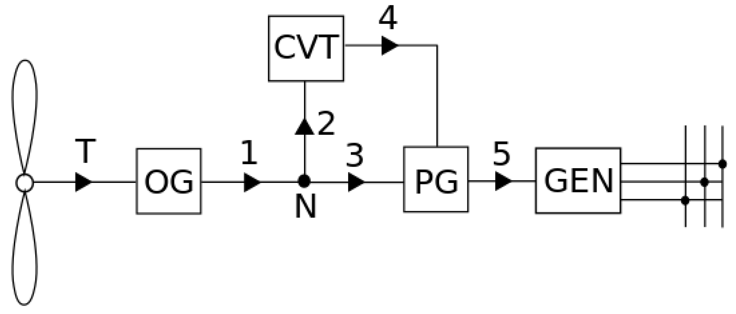
2.2.2. PS-HTS Configuration

Mantriota [27] demonstrated that the output split architecture is the one that, by minimizing the amount of power crossing the CVT (i.e., HTS in our case) leads to the optimal efficiency. Therefore, let us consider the architecture of the wind turbine powertrain shown in Figure 4. The powertrain is made of an planetary over-gear (OG) drive, a hydraulic CVT with infinitely large speed ratio ( r r = ), a planetary gearbox (PG) to combine the parallel power flows, and an electric generator (GEN). The following kinematic relations can be obtained, making reference to Figure 3:
τ O G = ω 1 ω T τ C V T = ω 4 ω 2 = n M n P = D P D M η v P η v M τ P G = ω 3 ω 4 ω 5 ω 4
with ω 1 = ω 2 = ω 3 . τ O G , τ C V T , and τ P G are the speed ratios of the OG, the CVT, and the PG, respectively. The overall speed ratio of the IVT ( τ I V T ) is
τ I V T = τ T 5 = ω T ω 5 = τ P G τ O G [ τ C V T ( τ P G 1 ) + 1 ] .
In order to obtain a Type III power flow, the τ T 5 must be a monotonic decreasing function of τ C V T [21]. If τ C V T M , τ I V T M are the maximum values of the CVT and the IVT respectively, and τ C V T m , τ I V T m are the minimum values of the CVT and the IVT respectively, then it follows that
τ C V T M = τ P G τ I V T m τ O G τ I V T m τ O G ( τ P G 1 ) τ C V T m = τ P G τ I V T M τ O G τ I V T M τ O G ( τ P G 1 ) .
The ratio range r r of the CVT is then calculated:
r r = τ C V T M τ C V T m = ( τ P G τ I V T m τ O G ) τ I V T M ( τ P G τ I V T M τ O G ) τ I V T m
In our case, τ C V T m = 0 when the pump displacement is set to zero, so from Equation (6), it follows that
τ P G = τ I V T M τ O G .
The torques applied at the pump and motor shafts have the following expressions:
T P = D P Δ p 2 π η P η v P T M = D M Δ p 2 π η v M η v M
where Δ p is the pressure differential. When the PS-HTS works at steady-state with a Type III power flow, the efficiency of the PG, the OG, and the CVT can be written as
η P G = P 5 P 3 + P 4 η O G = P 1 P T η C V T = P 4 P 2 .
Moreover, the rotational equilibrium of the PG at steady-state leads to
T 3 + T 4 + T 5 = 0
and the energy conservation of the link between paths 1, 2, and 3 leads to
P 1 = P 2 + P 3 .
The efficiency of the planetary gearbox η P G can then be written as
η P G = 1 ( 1 η O ) ω 5 ω 4 ω 5
where η O is the efficiency of the gearbox working with a stationary carrier. The ratio between P 5 and P 3 is
P 5 P 3 = τ P G τ O G τ I V T η P G .
Using Equations (10), (12) and (14), the input power of the CVT has the following expression:
P 2 = P T η O G ( 1 τ P G τ O G τ I V T ) 1 η C V T τ P G τ O G τ I V T .
The input power P 5 of the generator for wind speeds below the rated speed has the following expression:
P 5 = P G E N = η P G η O G P T τ P G τ O G τ I V T η C V T 1 η C V T τ P G τ O G τ I V T .
When the wind speed equals the rated wind speed, P 2 is equal to zero. The power generated by the turbine flows through the OG and PG. In this case, the latter works as a conventional gear train because the carrier is stationary. Therefore, the input power at the generator is
P 5 = P G E N = η O G η O P T .

3. Numerical Application

3.1. Characteristics of the Wind Turbine and the Powertrains

3.1.1. Wind Turbine Data

A numerical example is proposed to compare the performance of wind turbine systems equipped with HTS machines in two different architectures, namely, the in-line HTS and the PS-HTS with the output-split configuration. The turbine is supposed to have a rotor diameter D of 25 m , an electric generator with nominal angular speed n G E N of 1000 RPM , and a maximum power coefficient vallue of C P m a x = 0.5 at an optimal tip speed ratio of λ O p t = 8.5 . The turbine is assumed to work between a wake up velocity of V W S = 4.5 m / s and a maximum (cutout) wind velocity of V W c u t o u t = 25 m / s with a rated wind speed of V W R = 12 m / s .

3.1.2. HTS and Powertrain Data

The hydraulic CVT is realized by coupling two floating cup machines. A floating cup machine is a reversible variable displacement hydraulic machine with a maximum efficiency above 97%, which can work as pump or hydraulic motor. The first one is a pump and the second one is a motor; both are produced by Innas. The overall and the volumetric efficiency of the hydrostatic transmission are evaluated numerically using the analytical model described in [39] and tuning the model with the experimental data available in [35]. The overall efficiency of the floating cup pump and motor for the maximum displacement are shown in Figure 5. Notice that the efficiency is given as a function of the differential pressure and the angular velocity, so these maps can be used with good approximation to determine the efficiency of machines with different maximum displacements and so with different values of the nominal torques. Of course, for the given wind turbine data, the HTS system’s size is affected by the powertrain architecture. For the in-line HTS, following the model described in Section 2.2.1, the maximum displacement of the hydraulic machines is determined by assuming that the pressure is 150 bar at the rated wind speed. Therefore, the maximum displacement of the pump and the motor must be 1317 cm 3 / rev . Considering that a realistically large value of maximum displacement of this kind of machines is 250 cm 3 / rev , the requested value should be considered as the overall displacement of a many identical machines working in parallel. Further, the over-gear drive of the turbine is a planetary drive with a speed ratio τ O G equal to 10 and an estimated efficiency of η O G = 0.94 . For the PS-HTS configuration, instead, thanks to the fact that only a small part of the wind turbine power goes through the HTS, the size of HTS is far lower. In this case, the maximum displacement is determined by assuming that the pressure equals 150 bar when the wind speed is 9 km / h , because the maximum amount of power crosses the CVT at a wind speed equal to 9 km / h . By following this approach, the maximum displacement is found to be 180.9 cm 3 / rev . The over-gear drive is the same as in the previous case, and the planetary gear drive of the output split has a Willis gear ratio τ P G equal to 0.779 and an estimated fundamental efficiency (efficiency of the drive with a still carrier) of η O = 0.98 . For the reader’s convenience, all data are summarized in Table 1. Our model does not consider the charge pump of the hydrostatic transmissions in any of the cases. However, we expect that by neglecting the power consumption of the charge pump, which is supposed to be somehow proportional to power through the hydrostatic transmission, the comparison between the architectures will be safe, even though the absolute performance will be a little overestimated.

3.2. Results and Discussion

This section compares the performances of the variable speed wind turbine equipped with the powertrain architectures presented above. As mentioned, the displacement of the hydraulic machines is bigger in the in-line HTS than in the PS-HTS ( D m a x = 1317 cm 3 / rev vs. 180.9 cm 3 / rev ), because, in the former case, the hydrostatic transmission is crossed by the whole power produced by the wind turbine. The speed ratio of the hydraulic CVT is shown in Figure 6 as a function of the wind speed for the two architectures. The speed ratio is varied in the range of wind speed corresponding to region 2 where the turbine rotor runs with variable speed and the generator speed is constant. The rotational speed ω T of the rotor must increase with as the wind speed increases in order to keep λ constant and equal to its optimal value. In the case of the in-line HTS, the speed ratio must decrease at increasing values of ω T , whereas in the case of the power split HTS, the overall ratio is a decreasing function of the speed ratio of the speed ratio of the CVT; thus, the speed ratio of the CVT must increase. This is not a problem for the HTS CVT since the rotation of the machine only depends on the locations of the high and low pressure sides of the hydraulic circuit. It can be noticed that the absolute value of the speed ratio is far larger in the case of the in-line HTS. At wind speeds greater than the rated wind speed, the speed ratio of the CVT must remain constant; in this working range, the blade pitch angle is regulated to also keep the power and angular velocity values of the turbine constant (thus the efficiency of the energy conversion is reduced properly).
In Figure 7, the power crossing the CVT is shown as a function of the wind speed for both architectures. The PS-HTS configuration keeps the value of power crossing the CVT lower than the power crossing the whole transmission. Thus, the power across the CVT in the PS-HTS configuration is always much smaller than in the in-line configuration. In particular, when the value of the wind speed is larger than the rated wind speed, the power crossing the CVT in the PS-CVT architecture is zero because the speed ratio of the CVT is zero and all the power is conveyed across the mechanical path. Since the CVT is expected to have lower values of efficiency, this leads to a smaller dissipation of power in the case of the PS-HTS, at least for the values of wind speed where the difference in terms of power across the CVT is huge. The maximum amount of power crossing the HTS is about 25 kW at a wind speed of about 9 km / h , compared to the entire rated power of 250 kW which crosses the in-line HTS. This result has a huge consequence on the size of the HTS which is expected to be almost ten times smaller, as well as being cheaper, in the case of the PS-CVT architecture.
Indeed, the power loss in the powertrain (i.e., in the CVT and all other gear drives of the powertrain) is shown in Figure 8. The power loss in the PS-HTS architecture is much smaller (about one fourth) than the power loss in the in-line architecture in the regions where the wind speed is larger than the rated speed. Also, in the range of speed between the wake-up and the rated speeds, the power loss in the PS-HTS architecture is much smaller than in the in-line HTS.
As a consequence, the generated power is always larger in the case of the PS-HTS except in a small range where the values are very similar (see Figure 9). Since the mission of the wind turbine is to generate electric energy over a long period of time, it is necessary to understand the effectiveness of the proposed PS-HTS architecture calculating the potential Annual Energy Production (AEP) over a long period of time with realistic wind velocities for a given site. The AEP of the wind turbine for the two architectures is calculated for one given site. The station named FPL-01 is installed on the ridge between Manderugello and Piane del Ritornata in Italy at an altitude of 908 m. The frequency distribution of the speed measurements found at the aforementioned site at 50 m above the ground is shown in Figure 10.
The AEP is calculated in Figure 11 as a weighted average of the energy produced by the turbine at a given wind speed, in which the weights are derived from the frequency distribution f ( V W ) of wind speeds for a given site
A E P = A E P i = H f ( V W ) P ( V W )
where P ( V W ) is the electric power produced at speed V W , f ( V W ) is the frequency distribution of the wind velocity, and H = 8760 h / year is the number of hours per year.
In the integral value of the energy produced in one year, there will be substantial differences between the two configurations if the differences in terms of P ( V W ) are relevant for the values of V W characterized by large values of frequency f ( V W ) . A noticeable difference is observed in the range of wind velocity between 8 and 13 m/s. By using the values of the power generated by the turbine equipped with the two HTS architectures investigated in this paper, the AEP calculated for the in-line HTS architecture is equal to 702.9 MWh year whereas for the PS-HTS architecture, it equals 784.8 MWh year . This means that the PS-HTS allows 10% more energy to be harvested in a year than the in-line HTS architecture, with a hydraulic transmission of about one-seventh the size.

4. Conclusions

In this paper, the performances of two continuously variable transmission architectures for variable speed wind turbines were compared by means of a model-based approach. The former one, proposed elsewhere in the literature [28,29], is a hydrostatic transmission placed in series with traditional wind turbine powertrain components (in-line HTS). The latter, already discussed in [27] and [32], is a power split hydrostatic transmission (PS-HTS), designed in such a way as to obtain a convenient power flow in the parallel architecture, reducing the power across the hydrostatic transmission and thus enhancing the efficiency of the whole powertrain. This idea is supported by the recent publication of encouraging results on high efficiency hydraulic motors and pumps, as in the case of the floating cup machine developed by Innas [37] and the modelling and simulations developed in this paper. For our purposes, we developed and implemented a model of the hydrostatic transmission to give a good approximation of its efficiency, and we considered two powertrain designs, namely the series and the parallel architectures. Thus, we made some calculations of the performance achievable through both of them.
The results can be summarized in a few sentences:
  • By means of the power split architecture, it is possible to downsize the hydrostatic transmission. For instance, if a wind turbine with the characteristics summarized in Table 1 is considered, the needed pump and motor displacements are reduced from 1317 cm 3 / rev to 180.9 cm 3 / rev ; thus, the hydrostatic transmission is much smaller and cheaper (even though an additional planetary gear box must be considered).
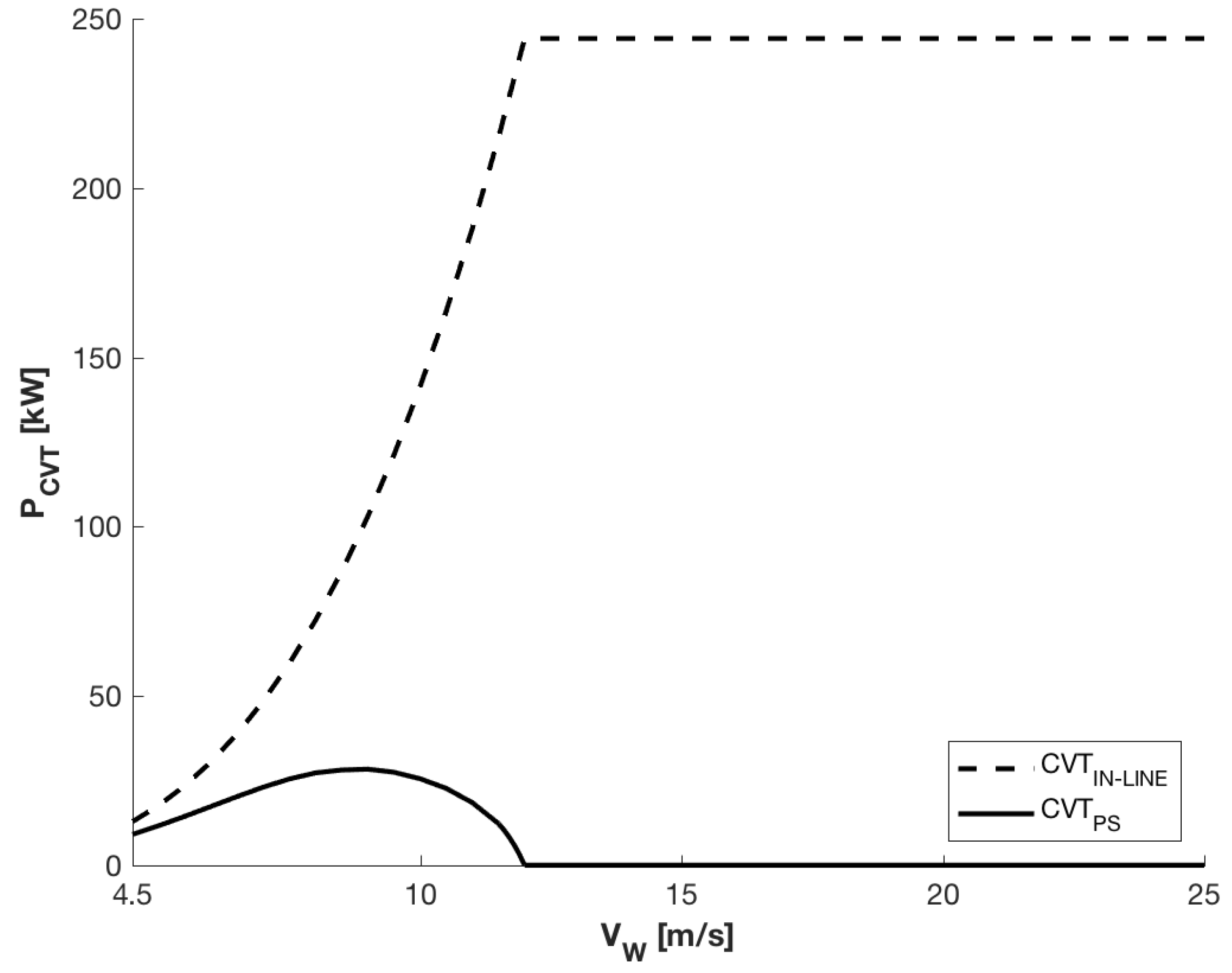
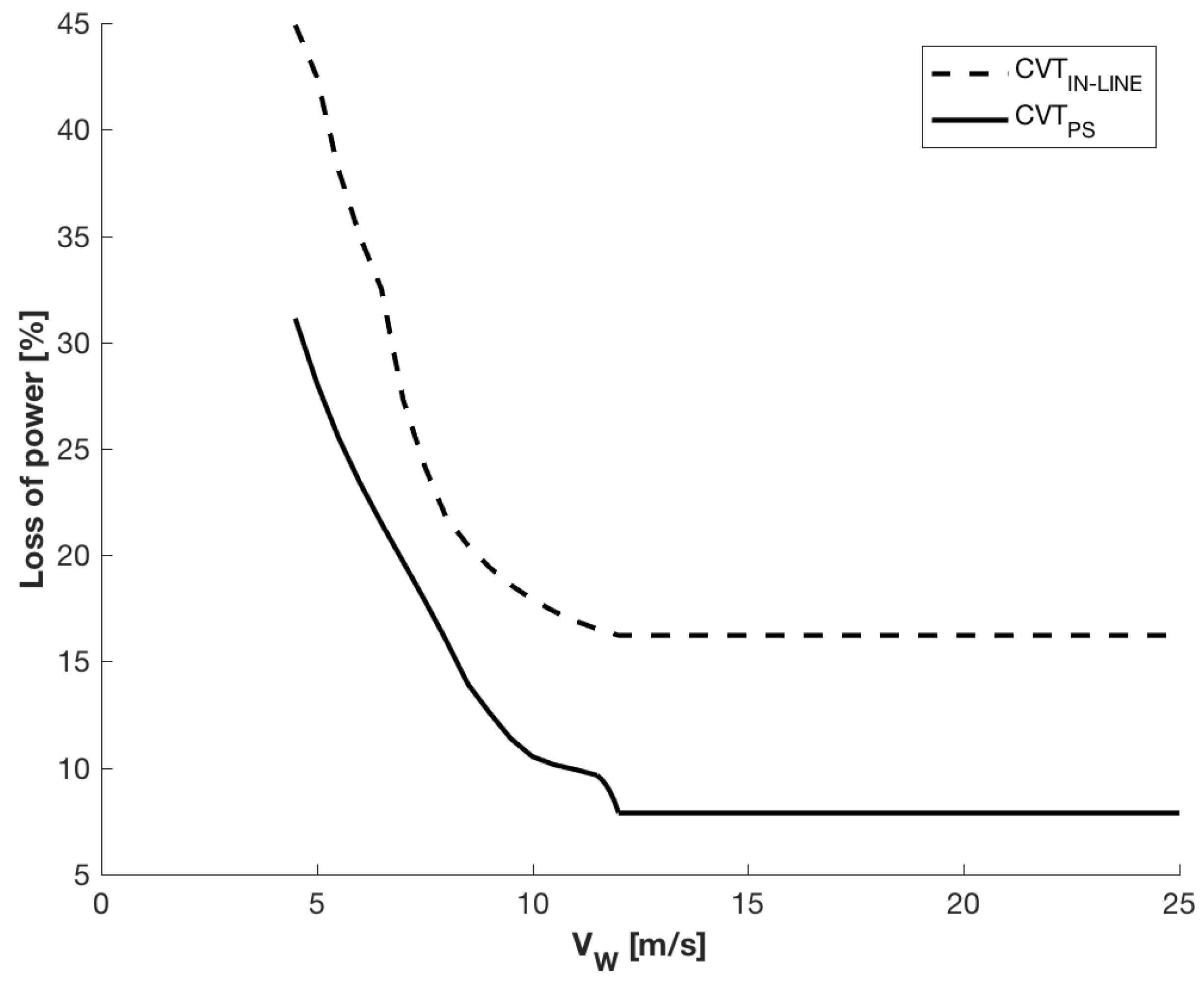
  • In the power split architecture, only a small fraction of the power (max 10–11%) goes across the hydrostatic transmission; thus, the overall power loss is smaller, in particular, at the rated power (the power loss is about one-fourth). In principle, a 100 kW HTS can be used in a 1 MW wind turbine thanks to the power split mechanism.
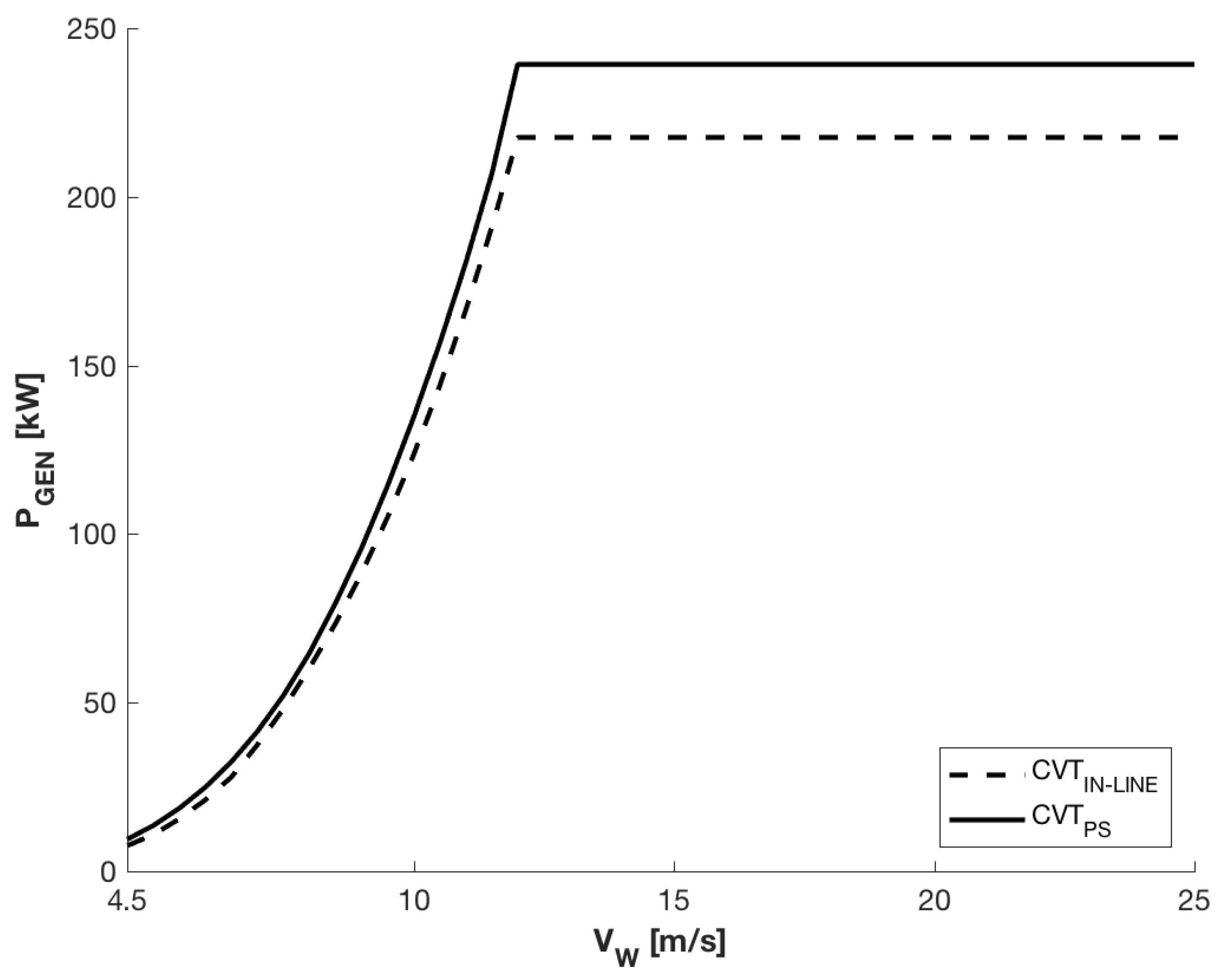
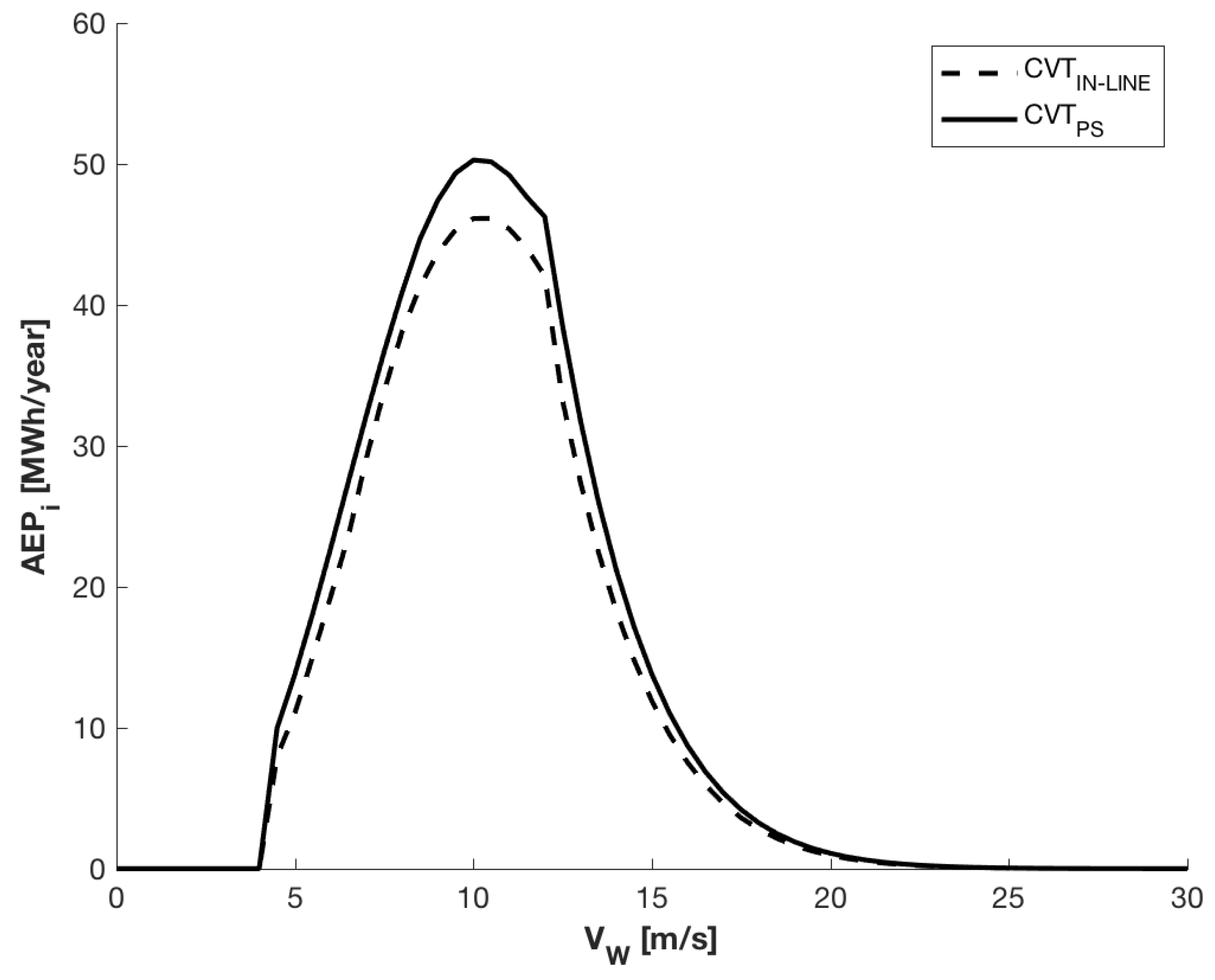
  • The estimated increase of the annual energy production is about 10% with almost no additional costs (as determined by calculations performed on a typical site). This encourages us to continue with the development of prototypical wind turbine systems equipped with power split HTS.

Author Contributions

F.B. supported the development of the simulation programs and wrote most of the manuscript; G.M. (team leader) developed the idea and revised the results; M.V. developed the simulations and arranged most of the figures.

Funding

This research received no external funding.

Conflicts of Interest

The authors declare no conflict of interest.

Abbreviations

The following abbreviations are used in this manuscript:
HTShydrostatic transmissions
PSpower-split
CVTcontinuously variable transmission
IVTinfinitely variable transmission
PGplanetary gear train
OGover-gear drive
GENelectric generator
AEGannual energy production

References

  1. Lalor, G.; Mullane, A.; O’Malley, M. Frequency control and wind turbine technologies. IEEE Trans. Power Syst. 2005, 20, 1905–1913. [Google Scholar] [CrossRef]
  2. Burton, T.; Jenkins, N.; Sharpe, D.; Bossanyi, E. Wind Energy Handbook; John Wiley & Sons: Hoboken, NJ, USA, 2011. [Google Scholar]
  3. de Vries, E. Wind turbine drive systems: A commercial overview. Electr. Drives Direct Drive Renew. Energy Syst. 2013, 139–157. [Google Scholar] [CrossRef]
  4. Polinder, H.; Ferreira, J.A.; Jensen, B.B.; Abrahamsen, A.B.; Atallah, K.; McMahon, R.A. Trends in wind turbine generator systems. IEEE J. Emerg. Sel. Top. Power Electron. 2013, 1, 174–185. [Google Scholar] [CrossRef]
  5. Höhn, B.R. Future transmissions for wind turbines. In Applied Mechanics and Materials; Trans Tech Publications: Zurich, Switzerland, 2011; Volume 86, pp. 18–25. [Google Scholar]
  6. Mueller, M.; Zavvos, A. Electrical Generators for Direct Drive Systems: A Technology Overview; Woodhead: Oxford, UK, 2013. [Google Scholar]
  7. Santhanagopalan, V.; Rotea, M.; Iungo, G. Performance optimization of a wind turbine column for different incoming wind turbulence. Renew. Energy 2018, 116, 232–243. [Google Scholar] [CrossRef]
  8. Asl, H.J.; Yoon, J. Power capture optimization of variable-speed wind turbines using an output feedback controller. Renew. Energy 2016, 86, 517–525. [Google Scholar] [CrossRef]
  9. Chen, Z.; Guerrero, J.M.; Blaabjerg, F. A review of the state of the art of power electronics for wind turbines. IEEE Trans. Power Electron. 2009, 24, 1859–1875. [Google Scholar] [CrossRef]
  10. Jamieson, P. Innovation in Wind Turbine Design; John Wiley & Sons: Hoboken, NJ, USA, 2011. [Google Scholar]
  11. Nejadkhaki, H.K.; Chaudhari, S.; Hall, J.F. A design methodology for selecting ratios for a variable ratio gearbox used in a wind turbine with active blades. Renew. Energy 2018, 118, 1041–1051. [Google Scholar] [CrossRef]
  12. Hall, J.F.; Mecklenborg, C.A.; Chen, D.; Pratap, S.B. Wind energy conversion with a variable-ratio gearbox: Design and analysis. Renew. Energy 2011, 36, 1075–1080. [Google Scholar] [CrossRef]
  13. Hall, J.F.; Chen, D. Performance of a 100 kW wind turbine with a Variable Ratio Gearbox. Renew. Energy 2012, 44, 261–266. [Google Scholar] [CrossRef]
  14. Giallanza, A.; Porretto, M.; Cannizzaro, L.; Marannano, G. Analysis of the maximization of wind turbine energy yield using a continuously variable transmission system. Renew. Energy 2017, 102, 481–486. [Google Scholar] [CrossRef]
  15. Mangialardi, L.; Mantriota, G. The advantages of using continuously variable transmissions in wind power systems. Renew. Energy 1992, 2, 201–209. [Google Scholar] [CrossRef]
  16. Mangialardi, L.; Mantriota, G. Automatically regulated CVT in wind power systems. Renew. Energy 1994, 4, 299–310. [Google Scholar] [CrossRef]
  17. Tyreas, G.C.; Nikolakopoulos, P.G. Development and friction estimation of the Half-Toroidal Continuously Variable Transmission: A wind generator application. Simul. Model. Pract. Theory 2016, 66, 63–80. [Google Scholar] [CrossRef]
  18. Bottiglione, F.; Mantriota, G. MG-IVT: An infinitely variable transmission with optimal power flows. J. Mech. Des. 2008, 130, 112603. [Google Scholar] [CrossRef]
  19. Bottiglione, F.; Mantriota, G. Reversibility of power-split transmissions. J. Mech. Des. 2011, 133, 084503. [Google Scholar] [CrossRef]
  20. Yang, F.; Feng, J.; Zhang, H. Power flow and efficiency analysis of multi-flow planetary gear trains. Mech. Mach. Theory 2015, 92, 86–99. [Google Scholar] [CrossRef]
  21. Mangialardi, L.; Mantriota, G. Power flows and efficiency in infinitely variable transmissions. Mech. Mach. Theory 1999, 34, 973–994. [Google Scholar] [CrossRef]
  22. Bottiglione, F.; De Pinto, S.; Mantriota, G. Infinitely Variable Transmissions in neutral gear: Torque ratio and power re-circulation. Mech. Mach. Theory 2014, 74, 285–298. [Google Scholar] [CrossRef]
  23. Mantriota, G. Performances of a parallel infinitely variable transmissions with a type II power flow. Mech. Mach. Theory 2002, 37, 555–578. [Google Scholar] [CrossRef]
  24. Mantriota, G. Performances of a series infinitely variable transmission with type I power flow. Mech. Mach. Theory 2002, 37, 579–597. [Google Scholar] [CrossRef]
  25. Jelaska, D.; Podrug, S.; Perkušić, M. Kinematic synthesis of a novel type of the series of transmissions with independently controllable output speed. Mech. Mach. Theory 2016, 103, 189–201. [Google Scholar] [CrossRef] [Green Version]
  26. Jelaska, D.; Podrug, S.; Perkušić, M. A novel hybrid transmission for variable speed wind turbines. Renew. Energy 2015, 83, 78–84. [Google Scholar] [CrossRef]
  27. Mantriota, G. Power split transmissions for wind energy systems. Mech. Mach. Theory 2017, 117, 160–174. [Google Scholar] [CrossRef]
  28. Liu, H.; Lin, Y.; Shi, M.; Li, W.; Gu, H.; Xu, Q.; Tu, L. A novel hydraulic-mechanical hybrid transmission in tidal current turbines. Renew. Energy 2015, 81, 31–42. [Google Scholar] [CrossRef]
  29. Yin, X.X.; Lin, Y.G.; Li, W.; Liu, H.W.; Gu, Y.J. Output power control for hydro-viscous transmission based continuously variable speed wind turbine. Renew. Energy 2014, 72, 395–405. [Google Scholar] [CrossRef]
  30. Pandiaraj, K.; Taylor, P.; Jenkins, N.; Robb, C. Distributed load control of autonomous renewable energy systems. IEEE Trans. Energy Convers. 2001, 16, 14–19. [Google Scholar] [CrossRef] [Green Version]
  31. Miao, Z.; Fan, L.; Osborn, D.; Yuvarajan, S. Wind farms with HVdc delivery in inertial response and primary frequency control. IEEE Trans. Energy Convers. 2010, 25, 1171–1178. [Google Scholar] [CrossRef]
  32. Shamshirband, S.; Petković, D.; Amini, A.; Anuar, N.B.; Nikolić, V.; Ćojbašić, Ž.; Kiah, M.L.M.; Gani, A. Support vector regression methodology for wind turbine reaction torque prediction with power-split hydrostatic continuous variable transmission. Energy 2014, 67, 623–630. [Google Scholar] [CrossRef]
  33. Johnson, K.E.; Pao, L.Y.; Balas, M.J.; Fingersh, L.J. Control of variable-speed wind turbines: standard and adaptive techniques for maximizing energy capture. IEEE Control Syst. 2006, 26, 70–81. [Google Scholar]
  34. Dasgupta, K. Analysis of a hydrostatic transmission system using low speed high torque motor. Mech. Mach. Theory 2000, 35, 1481–1499. [Google Scholar] [CrossRef]
  35. Rampen, W. Hydraulic Transmissions for Hybrid Vehicles; Artemis Intelligent Power LTD: Loanhead, Scotland, 2008. [Google Scholar]
  36. Rydberg, K.E. On Performance Optimization and Digital Control of Hydrostatic Drives for Vehicle Applications; Number Monograph; The National Academies of Sciences, Engineering, and Medicine: Washington, DC, USA, 1983. [Google Scholar]
  37. Achten, P.; Van den Brink, T.; Paardenkooper, T.; Platzer, T.; Potma, H.; Schellekens, M.; Vael, G. Design and testing of an axial piston pump based on the floating cup principle. Proc. SICFP 2003, 3, 805–820. [Google Scholar]
  38. Rydberg, K.E. Hydraulic hybrids—The new generation of energy efficient drives. In Proceedings of the 7th International Conference on Fluid Power Transmission and Control ICFP, Hangzhou, China, 7–10 April 2009; pp. 7–10. [Google Scholar]
  39. Costa, G.; Sepehri, N. Hydrostatic Transmissions and Actuators: Operation, Modelling and Applications; John Wiley & Sons: Hoboken, NJ, USA, 2015. [Google Scholar]
Figure 1. Typical turbine power.
Energies 11 03369 g001
Figure 2. The power coefficient C P as a function of the tip speed ratio λ .
Energies 11 03369 g002
Figure 3. Schematic of the in-line HTS configuration. OG is the over-gear drive, CVT is the continuously variable transmission (the HTS in this case), and GEN is the electric generator.
Energies 11 03369 g003
Figure 4. Schematic of the Power Split Hydraulic Transmission System (HTS) with output split configuration. OG is the overgear drive, CVT is the continuously variable transmission (the HTS in this case), PG is the Planetary Gearbox, and GEN is the electric generator.
Energies 11 03369 g004
Figure 5. Contour plot of the total efficiency of the floating cup (a) pump and (b) motor at full displacement. The contour plots were obtained through our physical model of the hydraulic machine obtained following [39] and the fitting data of [35], also in terms of partial displacement.
Energies 11 03369 g005
Figure 6. Transmission ratio of the (Left) power split HTS with a Type III power flow and (Right) in-line HTS.
Energies 11 03369 g006
Figure 7. Power across the hydraulic Continuously Variable Transmission (CVT) in the in-line HTS and in the PS-HTS. architectures.
Energies 11 03369 g007
Figure 8. Loss of power for the two architectures.
Energies 11 03369 g008
Figure 9. Power supplied to the generator in the two transmission configurations.
Energies 11 03369 g009
Figure 10. Wind frequency distribution at 50 m with its Weibull fitting—FPL-01 station.
Energies 11 03369 g010
Figure 11. Annual Energy Production (AEP) distribution of the wind turbine for the two architectures for the site characterized by the frequency distribution of wind speed shown in Figure 10.
Energies 11 03369 g011
Table 1. Main parameters of the wind turbine.
SystemParameterSymbolValue
Turbinerotor diameterD25 m
optimal tip speed ratio λ O p t 8.5
maximum value of power coefficient C P m a x 0.5
electric generator speed n G E N 1000 RPM
low threshold value of wind speed V W S 4.5 m / s
rated wind speed V W R 12 m / s
In-Line HTSover-gear speed ratio τ O G 10
over-gear efficiency η O G 0.94
pump displacement D P 1317 cm 3 / rev
motor displacement D M 1317 cm 3 / rev
PS-HTSover-gear speed ratio τ O G 10
over-gear efficiency η O G 0.94
hydraulic CVT ratio spread r r
pump displacement D P 180.9 cm 3 / rev
motor displacement D M 180.9 cm 3 / rev
planetary gear speed ratio τ P G 0.779
planetary gear efficiency with stationary carrier η O 0.98

