Article

Wound Synchronous Machine Sensorless Control Based on Signal Injection into the Rotor Winding

Department of Electrical Engineering, Pohang University of Science and Technology, 77 Cheongam-Ro, Nam-Gu, Pohang 37673, Korea
*
Author to whom correspondence should be addressed.
Energies 2018, 11(12), 3278; https://doi.org/10.3390/en11123278
Submission received: 29 October 2018 / Revised: 14 November 2018 / Accepted: 21 November 2018 / Published: 24 November 2018
(This article belongs to the Special Issue Advances in Rotating Electric Machines)

Abstract

:
A sensorless position scheme was developed for wound synchronous machines. The demodulation process is fundamentally the same as the conventional signal-injection method. The scheme is different from techniques for permanent-magnet synchronous machines, in that it injects a carrier signal into the field (rotor) winding. The relationship between the high-frequency current responses and the angle estimation error was derived with cross-coupling inductances. Furthermore, we develop a compensation method for the cross-coupling effect, and present several advantages of the proposed method in comparison with signal injection into the stator winding. This method is very robust against magnetic saturation because it does not depend on the saliency of the rotor. Furthermore, the proposed method does not need to check the polarity at a standstill. Experiments were performed to demonstrate the improvement in the compensation of cross-coupling, and the robustness against magnetic saturation with full-load operation.

1. Introduction

Although their speed is not so high, electrical vehicles (EVs) and hybrid EVs (HEVs) are steadily growing their share in the market. Today, permanent-magnet synchronous machines (PMSMs) are widely used in traction applications because of their superior power density and high efficiency. However, the permanent-magnet (PM) materials, typically neodymium (Nd) and dysprosium (Dy), are expensive, and their price fluctuates depending on political situations. Therefore, some research has been directed to developing Nd-free motors. Wound synchronous machines (WSM) is a viable alternative to a PMSM. The main advantage of a WSM is that it has an additional degree of freedom in the field-weakening control because the rotor field can be adjusted [1,2,3].
There are two types of sensorless angle detection techniques: back-EMF-based and signal-injection methods. The former is based on the relative magnitudes of d and q-axis EMFs, whereas the latter is based on the spatial saliency of rotor. The back-EMF-based methods are reliable and superior in the medium- and high-speed regions [4,5,6,7,8,9,10]. However, they exhibit poor performance in the low-speed region owing to lack of the “observability” [11].
On the other hand, signal-injection methods work well in the zero-speed region, even with a full load [12,13,14,15,16,17,18,19]. The injection method does not use the magnetic polarity; it requires the use of a polarity-checking method before starting [14,15]. The signal-injection method is not feasible in some saturation regions where the d and q-axis inductances are close to each other [16,17]. The cross-coupling inductance refers to an incremental inductance developed by the current in the quadrature position. Cross-coupling, being another saturation phenomenon, becomes significant as the load increases. Zhu et al. [18] showed that cross-coupling caused an offset error in the angle estimation and proposed a method eliminating it. However, the cross-coupling inductances change considerably depending on the current magnitudes. Therefore, a lookup table should be used for its compensation method. A group of researchers are working together toward developing specialized motors that are suitable for signal injection [19].
Similar to PMSMs, back-EMF-based sensorless methods were developed for WSMs [20,21,22,23]. Boldea et al. [22] proposed an active-flux-based sensorless method, and this paper presents good experimental results in low-speed operation with a heavy load. Amit et al. [23] used a flux observer in the stator flux coordinate. Recently, the sensorless signal injection for WSM was published, whose carrier signal is injected to an estimated d-axis, and the response in estimated q-axis current [24,25]. Griffo et al. [24] applied a signal-injection method to a WSM to start an aircraft engine, and presented full-torque operation from zero to a high speed. Rambetius et al. [25] compared two detection methods when a signal was injected into the stator winding: one from a stator winding and the other from the field (rotor) winding.
Signal injection to the rotor winding of the WSM has been reported in recent years [26,27,28,29]. Obviously, detected signals from the (stator) d-q axes differ depending on rotor position. The stator voltage responses [26] and current responses [27,28,29] are checked to obtain rotor angle information using mutual magnetic coupling between the field coil and the stator coil. Using inverse sine function and q-axis current in the estimated frame, the position estimation algorithm was presented for a sensorless direct torque control WSM and it presented experimental results at zero speed [27]. Rambetius and Piepenbreier [28,29], included cross-saturation effects in the high-frequency model and presented the position estimation method using q-axis current in the estimation synchronous frame and linearization. The model was included in the stator but also in the field dynamics. It is a reasonable approach when a voltage as the carrier signal is injected to rotor winding. However, a 3 × 3 inductance matrix should be handled, and it is pretty complicated and difficult to analyze.
This paper extends the work in [30]. The signal is injected into the rotor winding, and the resulting high-frequency is detected from the stator currents. The effect of the cross-coupling inductances is modeled. Since the field current is modeled as a current source, 2 × 2 inductance matrix can be obtained. It is easy to calculate the inverse matrix and analyze the effect of the cross-coupling inductance on rotor angle estimation. The d q -axes stator flux linkage are obtained by finite-element analysis. Using the flux linkage, the d q -axes self-inductances and the mutual inductances between the stator and rotor are obtained and analyzed. Then, an offset angle caused by the cross-coupling inductances is straightforwardly derived. Using both d q -axes currents in the misaligned frame and inverse tangent function, the rotor angle estimation algorithm is developed without linearization. The offset angle caused by cross-coupling effect is directly compensated, and the stability issue of the compensation method is analyzed. Furthermore, it explains why injection into the rotor winding is more robust than the existing methods. Finally, experimental results verify that the rotor position is obtained accurately at standstill and very low speed.
This paper is organized as follows. In Section 2, the WSM model is derived with coupling inductances. In Section 3, the current responses in misaligned coordinate are derived and a sensorless method is proposed. Some advantages of the field signal-injection method are presented in comparison with stator signal injection in Section 4. Section 5 presents a performance comparison between the injection methods to stator and rotor. In Section 6, the performance of the sensorless method is demonstrated by experiment. Finally, in Section 7, some conclusions are drawn.

2. Modeling of a WSM

A schematic diagram of a WSM is depicted in Figure 1. Please note that a high-frequency signal is injected into the field winding via a slip ring.

2.1. WSM Voltage Model

From [31] (in Chapter 11), the voltage equations of WSM are given as
v d e = r s i d e + d d t λ d e ω e λ q e ,
v q e = r s i q e + d d t λ q e + ω e λ d e ,
where v d e , v q e are the d and q-axis voltages and ω e is the electrical angular frequency; the superscript e represents the synchronous (rotating) reference frame. Note that d d t λ d e and d d t λ q e are important terms for sensorless signal-injection methods because the terms are represented as the induced voltage caused by the high-frequency current.
The stator flux linkages of a WSM in the synchronous frame are expressed as λ d e ( i d e , i q e , i f ) , and λ q e ( i d e , i q e , i f ) , where λ d e and λ q e are non-linear functions [3]; λ d e and λ q e are the d and q-axes stator flux linkage; i d e and i q e are the d and q-axes currents; and i f is the field current referred to stator. Note that i f is represented by i f = 2 3 N s N f d i f [31], where i f is the field current, N s and N f d are the number of stator coil and field coil turns. To take account of the cross-coupling effect, the following equations are derived by the chain rule
d λ d e d t = λ d e i d e L d d d i d e d t + λ d e i q e L d q d i q e d t + λ d e i f L d f d i f d t
d λ q e d t = λ q e i q e L q q d i q e d t + λ q e i d e L q d d i q e d t + λ q e i f L q f d i f d t ,
where L d d and L q q are the self (incremental) inductances, and L d q and L q d are the cross-coupling (incremental) inductances of the stator coil [16]. L d f is the mutual (incremental) inductance between the d-axis and the field coils, and L q f is the cross-coupling (incremental) inductance between the stator and field coils. The d-axis inductance can be decomposed as the sum of the mutual and leakage inductances:
L d d = L d f + L l s ,
where L l s is the leakage inductance of the stator. Therefore, L d d L d f L q f .
Substituting (3) and (4) into (1) and (2), the voltage equations are obtained as
v d e = r s i d e + L d d d i d e d t + L d q d i q e d t + L d f d i f d t ω e λ q e
v q e = r s i q e + L q q d i q e d t + L q d d i d e d t + L q f d i f d t + ω e λ d e .
Using (5)–(7), an equivalent circuit can be constructed as shown in Figure 2.
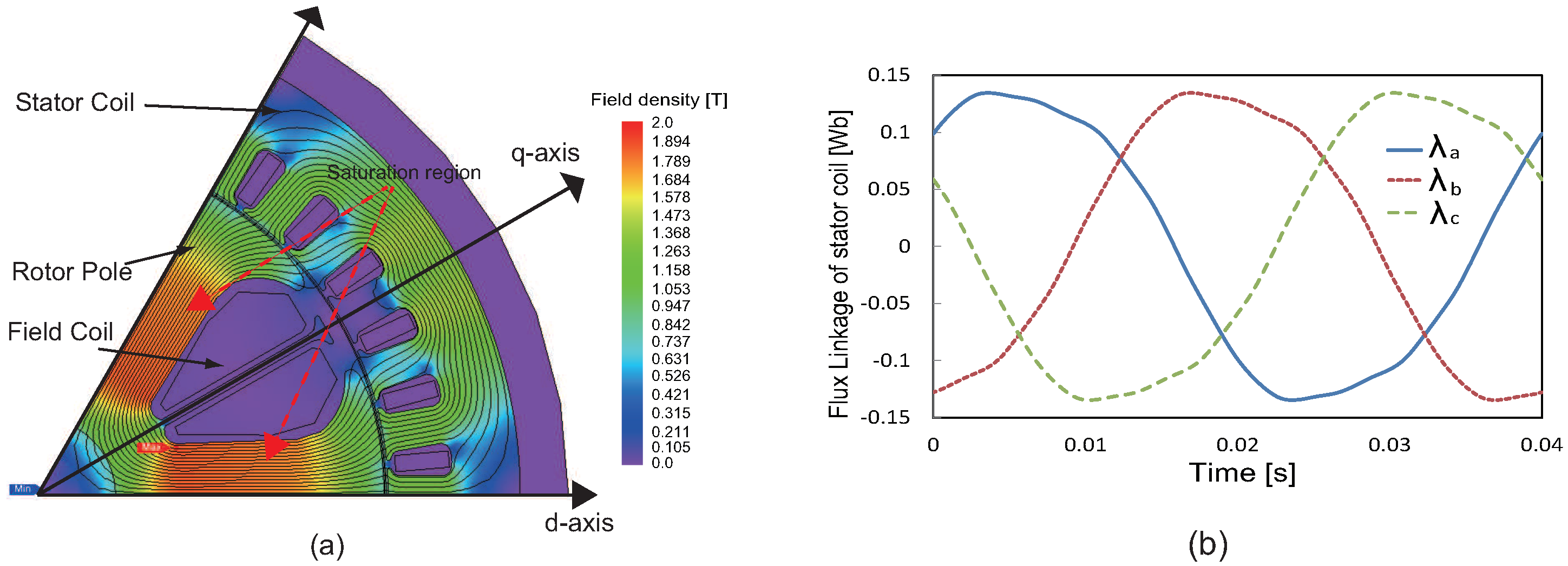
Figure 3a shows a FEM model of WSM used in this experiment. The motor has six salient poles, the continuous rated current is 161 Arms, and the maximum power is 65 kW. The other parameters are listed in Table 1. Figure 3b shows plots of the a-, b-, c-phase flux linkages in the stationary frame as the rotor rotates at 500 r/min, which were obtained through finite-element method (FEM) calculations. The d - q axis flux linkages are obtained using
λ d e λ q e = 2 3 cos θ e sin θ e sin θ e cos θ e 1 1 2 1 2 0 3 2 3 2 λ a λ b λ c ,
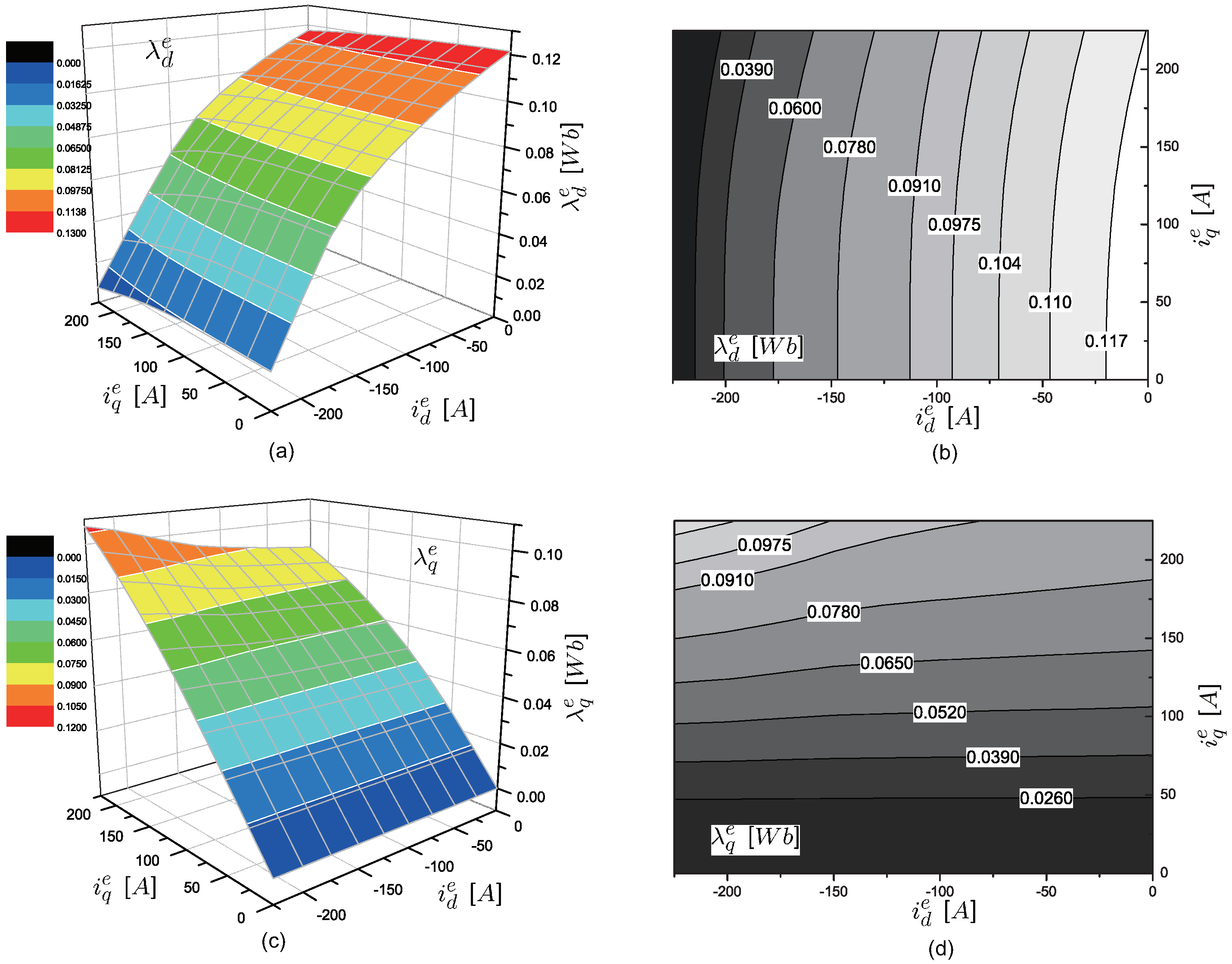
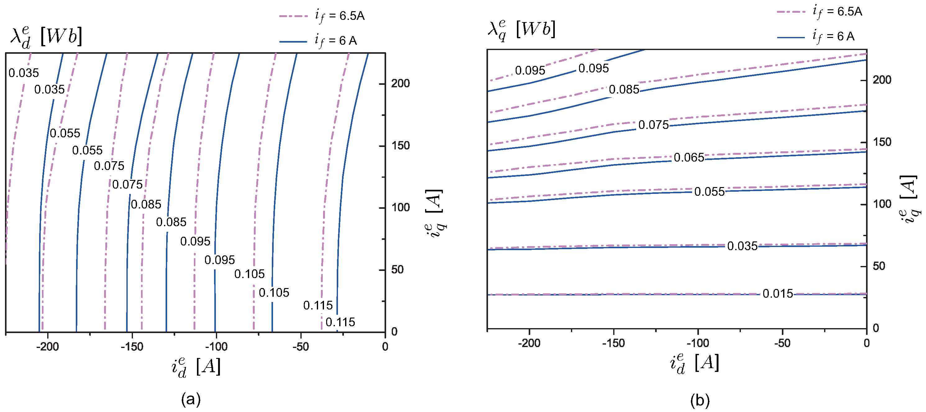
where θ e is the electrical angle. Figure 4 shows the plots of λ d e ( i d e , i q e , i f ) and λ q e ( i d e , i q e , i f ) in the ( i d e , i q e ) plane when i f = 6 A. Please note that λ d e changes more, i.e., the slope becomes steeper as the d-axis current increases negatively. When i q e is under 50 A, i q e has little effect on λ d e . However, when i q e is over 100 A, λ d e decreases more as i q e increases. It is called “cross-coupling phenomenon”. Figure 5 shows a contour of λ d e ( i d e , i q e , i f ) and λ q e ( i d e , i q e , i f ) when i f = 6 A or i f = 6.5 A. λ d e seems to be proportional to i f . But, in Figure 5b, λ q e with i f = 6 A seems to be the same λ q e with i f = 6.5 A when i q e is under 50 A. But, it is clear that λ q e decreases as i q e increases when i q e is over 100 A.

2.2. Incremental Inductance Calculations

As shown in [18,32], the incremental inductances are calculated through numerical differentiation:
L d q = λ d e i d e λ d e ( i d e , i q e + Δ i q e , i f ) λ d e ( i d e , i q e , i f ) Δ i q e L d f = λ d e i f e λ d e ( i d e , i q e , i f + Δ i f ) λ d e ( i d e , i q e , i f ) Δ i f .
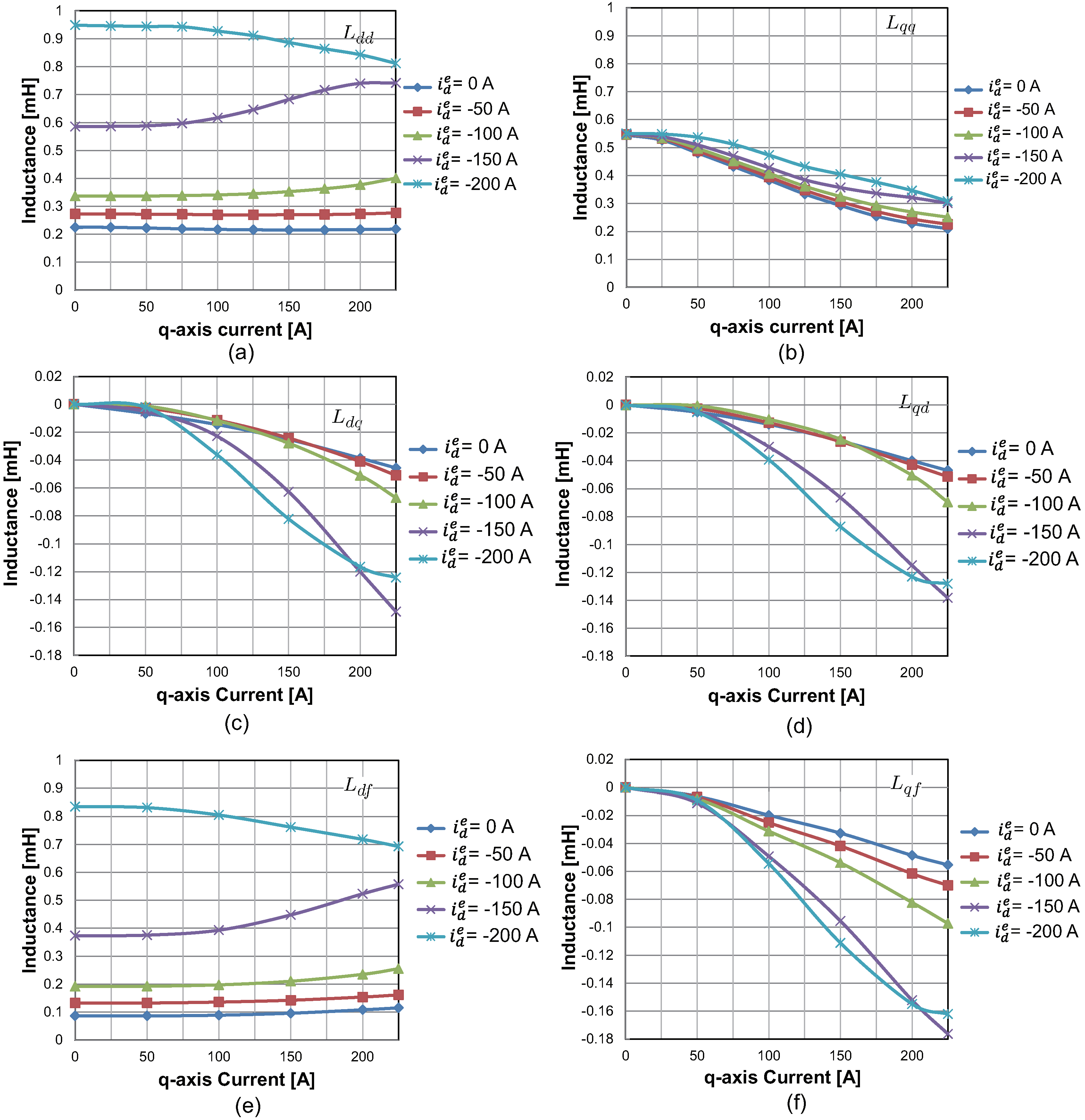
The rest of the inductances are obtained similarly. Figure 6 shows L d d , L q q , and L d q under various current conditions. From Figure 6a, L d d is, in general, independent of the q-axis current when i q is not so high, whereas it depends strongly on the d-axis current, i.e., L d d increases as i d e increases negatively. This is because the rotor core becomes free from the saturation caused by the field current. Specifically, the negative d-axis current induces a field in the opposite direction, i.e., it cancels the rotor field.
In addition, also from Figure 6b–d, L q q , L d q , and L q d decrease as i q e increases. Figure 6c,f show plots of L d f and L q f that show the mutual inductances from the field winding, i.e., the flux variation induced by the field current. Because the high-frequency probing signal is injected into the field coil, L d f and L q f play a crucial role in this work. Comparing Figure 6a,c, the shapes of L d d and L d f are similar. It is because they are the same except the leakage inductance, as shown in (5). Note from Figure 6c,d,f, the cross-coupling inductances ( L d q , L q d , L q f ) behave similarly and have negative values. Because of the non-linear magnetic property of core, the core saturation give rise to cross-coupling phenomenon. For instance, when the field current is fixed at 6 A, λ d ( i d e = 0 , i q e = 50 ) = 0.121345 Wb and λ d ( i d e = 0 , i q e = 200 ) = 0.118252 Wb were obtained in Figure 4b. Despite the same d-axis current, the d-axis flux linkages decrease as i q e increases. This is because the q-axis current saturates the core deeper, and it affects d-axis flux linkages to be reduced. Consequently, the cross-coupling inductance between d and q-axis, L d q , can be negative values, the phenomenon is also exhibited in PMSMs [18]. Correspondingly, the q-axis flux linkages decrease as i f or i d e increases in Figure 4d and Figure 5b. Therefore, L q d and L q f have negative values.
When a signal is injected into the field winding, the current responses are monitored in the stator winding via L d f and L q f . The use of L q f is different from PMSM signal-injection methods because it provides another signal path to the q-axis besides the one formed by rotor saliency.

3. High-Frequency Model of a WSM

As shown in Figure 1, the WSM has a separate field controller, which feeds i f to the field winding via a slip ring and brush. A high-frequency carrier is superposed on the field current. Then, the signal is detected on the stator winding, on which the rotor angle is estimated. The field current controller supplies
i f ( t ) = I f 0 + i f h ( t ) = I f 0 I h cos ω h t ,
where I f 0 and I h are the amplitudes of the dc and ac components, and ω h is the angular speed of the carrier. Furthermore, the d and q-axis currents can be separated as
i d e = i d 0 e + i d h e ,
i q e = i q 0 e + i q h e ,
where i d 0 e and i q 0 e are dc components current, i d h e and i q h e are the high-frequency components. Substituting (9)–(11) into (6) and (7), the voltage equations are written as
v d e v q e = r s 0 0 r s i d e i q e + L d d L d q L q d L q q d d t i d 0 + i d h e i q 0 + i q h e + ω e λ q e ω e λ d e + L d f L q f d d t ( I f 0 I h cos ω h t ) .
Please note that i d h e and i q h e are induced by the high-frequency part of i f . From (12), the terms r s i d e , r s i q e , ω e λ q e , and ω e λ d e are neglected because ω h is much larger than ω e , ω h L d d r s , and ω h L q q r s . Thus, it is following that
v d e v q e = L d d L d q L q d L q q d d t i d 0 e + i d h e i q 0 e + i q h e + L d f L q f d d t ( I f 0 I h cos ω h t ) .
Please note that L d d , L q q , L d q , L q d , L d f , and L q f are the incremental inductance in Section 2.2. It means that the inductances are calculated at a specific operating point, ( i d 0 e , i q 0 e , I f 0 ). Therefore, all inductances can be assumed the constant value at the operation point. Based on the superposition law at ( i d 0 e , i q 0 e , I f 0 ), the high-frequency part is separated as
0 0 = L d d L d q L q d L q q d d t i d h e i q h e + ω h L d f L q f I h sin ω h t .
Thus, the solution to (14) is obtained such that
i d h e ( t ) i q h e ( t ) = I h α A α B cos ω h t + i d h e ( 0 ) i q h e ( 0 ) ,
where
α A = L q q L d f L d q L q f L d d L q q L d q L q d α B = L q d L d f + L d d L q f L d d L q q L d q L q d .
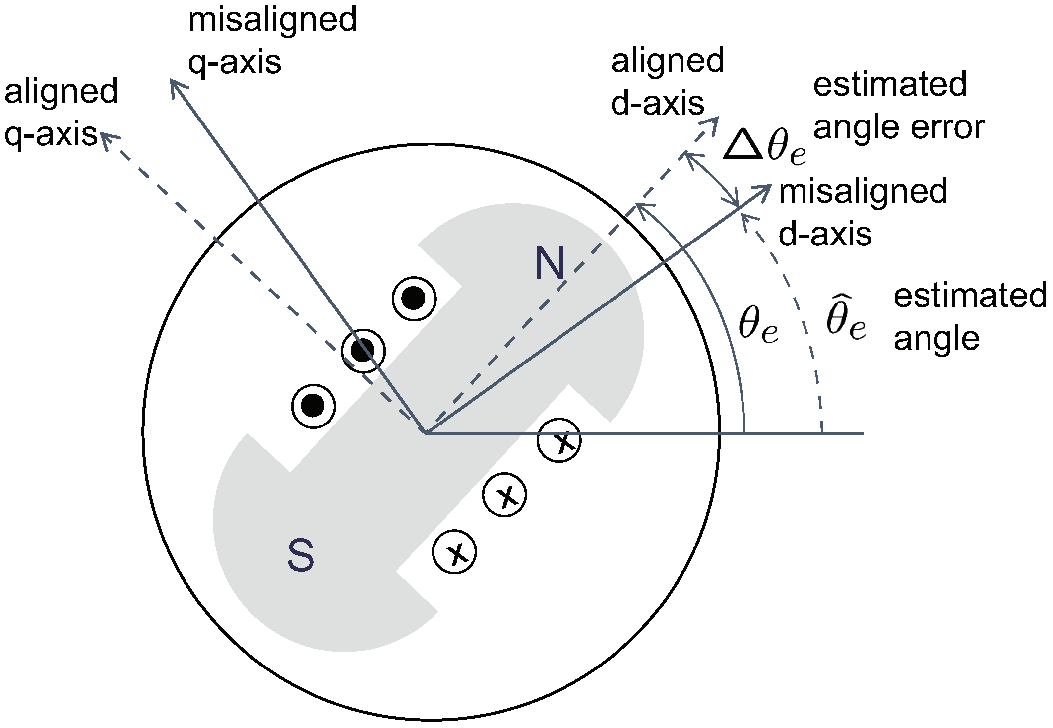
Please note that (15) is the equation in the synchronous (rotor) frame based on the right angle θ e . As shown in Figure 7, the angle of the misaligned frame is denoted by θ ^ e , and the angle error is defined as
Δ θ e = θ ^ e θ e ,
where Δ θ e S [ π , π ) .
It is assumed that current is measured in a misaligned frame, in which the currents are denoted by i ^ d h e and i ^ q h e . The current equation can be transformed to the misaligned frame by the following rotation matrix,
R ( Δ θ e ) = cos ( Δ θ e ) sin ( Δ θ e ) sin ( Δ θ e ) cos ( Δ θ e ) .
By multiplying (17) to (15), we obtain
i ^ d h e i ^ q h e = I h α A cos Δ θ e + α B sin Δ θ e α A sin Δ θ e + α B cos Δ θ e cos ω h t = I h α A 2 + α B 2 cos ( Δ θ e η ) sin ( Δ θ e η ) cos ω h t ,
where
η = tan 1 ( α B α A ) = tan 1 L q d L d f + L d d L q f L q q L d f L d q L q f .
Please note that η is an angle offset caused by the cross-coupling inductances. Specifically, η = 0 when L d q = L q d = L q f = 0 , which means that η is caused by the cross-coupling.

4. Position Estimation Using Signal Injection into the Rotor Winding

Phase currents are measured and transformed into an estimated frame. Then, a band-pass filter (BPF) is applied to i ^ d e and i ^ q e to remove the dc components. To perform synchronous rectification, cos ω h t is multiplied with i ^ d h e and i ^ q h e . Then, a low pass filter (LPF) is applied to extract the dc signals X and Y [33]:
X L P F ( i ^ d h e × cos ω h t ) I h 2 α A 2 + α B 2 cos ( Δ θ e η )
Y L P F ( i ^ q h e × cos ω h t ) I h 2 α A 2 + α B 2 sin ( Δ θ e η ) .
Using the filtered signals, the angle error Δ θ e can be estimated via
Δ θ e = tan 1 Y X + η .
Figure 8 shows a block diagram of the signal processing illustrating in the above. A lookup table for η is used to compensate the bias depending on the load condition and current angle. Finally, a phase locked loop (PLL) is employed to obtain an estimate θ ^ e .
The bandwidth of the filter has an impact on the estimation bandwidth. To enhance the performance, the bandwidth of PLL and filter should be increased. However, the high-frequency current ( i d h e , i q h e ) can be contaminated with a noise [34]. In practice, the noise limits the bandwidth of the filter and PLL.

4.1. The Analysis of Cross-Coupling Offset Angle η

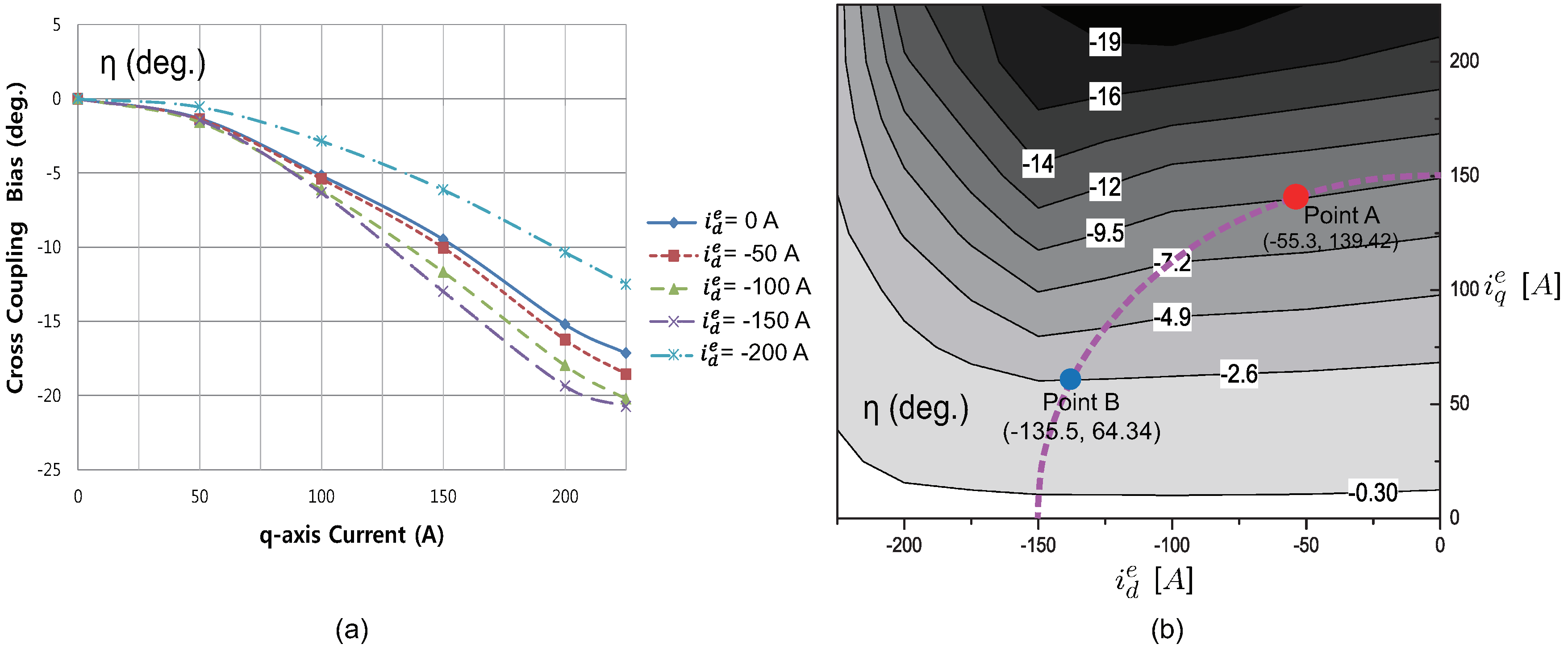
It is clear from (22) that the exact information of η is necessary to obtain an accurate value of Δ θ . On the other hand, η is a function of L d q , L q d , and L q f in (19), which change nonlinearly with the currents. For practical purposes, it is better to make a lookup table of η over ( i d e , i q e ) . Figure 9 shows the variations in η when the currents change. In general, the magnitudes of η increases as the core saturation develops. Note also that | η | increases with the d-axis current until i d e = 150 A. However, it has the smallest values when i d e = 200 A. That situation could be illustrated as follows: The rotor flux generated by the field winding is almost canceled out by the negative d-axis current, i d e = 200 A. More specifically, note that the ampere-turn of the field winding is N f d i f = 200 × 6 A - turns , where N f d is the number of turns of the field winding. The ampere-turn of the d-axis stator winding is equal to 3 2 × N a × i a = 3 2 × 6 × 2 3 × 200 = 1200 A-turns, where N a is the number of turns of a phase winding per pole, and the winding factor is assumed to be unity. That is, they are the same when i d e = 200 A. Hence, the core is relieved from the saturation induced by the field winding, when i d e = 200 A. Thus, the non-linear behavior of η is mitigated when i d e = 200 A.

4.2. The Compensation Method for Cross-Coupling Offset Angle η

The cross-coupling bias angle relies on the lookup table, which is the function of i d e and i q e . In practice, the d q -axes currents in the synchronous reference frame ( i d e , i q e ) are unknown in sensorless control. Thus, they are replaced by the d q -axes currents in misaligned frame, ( i ^ d e , i ^ q e ). However, the inaccurate compensation for η can be made by the difference between ( i d e , i q e ) and ( i ^ d e , i ^ q e ). Therefore, it has an effect on stability of the sensorless observer. To analyze the stability, define the function of η as
η = f ( i d e , i q e ) ,
f is shown in Figure 9. Using (17), the d q -axes currents in misaligned frame are derived as
i ^ d e i ^ q e = cos Δ θ e sin Δ θ e sin Δ θ e cos Δ θ e i d e i q e , = I s sin ( β Δ θ e ) cos ( β Δ θ e ) ,
where I s = i d e 2 + i q e 2 and β = tan 1 ( i d e / i q e ) . Using (24), the compensation offset angle is obtained by η c o m = f ( i ^ d e , i ^ q e ) . In Figure 8, Δ θ ^ e is the input of the PLL (tracking filter). Subtracting tan 1 Y X from the compensation angle η c o m , Δ θ ^ e can be calculated
Δ θ ^ e = Δ θ e + η η c o m = Δ θ e + f ( i d e , i q e ) f ( i ^ d e , i ^ q e ) = Δ θ e + f ( I s sin β , I s cos β ) f ( I s sin ( β Δ θ e ) , I s cos ( β Δ θ e ) ) = Δ θ e [ 1 + f ( I s sin ( β Δ θ e ) , I s cos ( β Δ θ e ) ) f ( I s sin β , I s cos β ) Δ θ e κ ] .
Please note that κ should be the positive value to ensure the stability of the PLL observer, i.e., κ 0 . If κ < 0 , the estimated position error will be amplified. Therefore, our task is to prove that κ is the positive value in the whole operation region. However, it is difficult for analytical demonstration because f is not mathematically represented and is highly non-linear. Figure 9b shows the contour of the cross-bias angle, η . From (24), ( i ^ d e , i ^ q e ) are rotated by Δ θ e clockwise. It is evident that f ( i ^ d e , i ^ q e ) slightly decreases as Δ θ e increases. It means that κ is maintained over 0, i.e., κ 0 . It is because f ( i ^ d e , i ^ q e ) f ( i d e , i q e ) Δ θ > 1 . For example, the point B is ( i d e , i q e ) and the point A is ( i ^ d e , i ^ q e ) in Figure 9b. β is 64.6 ° and Δ θ is 42.9 ° . Substituting point A and B into (26), it was obtained as Δ θ ^ e = Δ θ e ( 1 + 9.5 ° + 2.6 ° 42.9 ° ) = 0.84 Δ θ e . Therefore, the convergence of the estimated angle error can be locally guaranteed due to κ 0 . By contrast, PMSMs have a positive offset angle caused by cross-coupling inductance [15,18] when q-axis current is positive. It shows that the offset angle increases as the q-axis current increases. An offset angle compensation method for PMSM was reported [35], and this paper proposed two different estimation angles: the saliency-based angle and the estimation rotor angle (compensated). Consequently, double-synchronous frames should be used, it causes the increasing of the calculation burden. In comparison, the proposed method has only one estimated synchronous frame.

5. Performance Comparison between Rotor and Stator Injection

Sensorless control performance degrades as the load increases because the inductances vary significantly along with core saturation. Specifically, the saliency ratio decreases, i.e., L d d L q q [17,19]. The accuracy of a sensorless method is determined by signal-to-noise ratio, which the saliency ratio affects. In this section, a common method of injecting a signal into the stator is also considered for the purpose of comparison.
Rambetius et al. studied the WSM model by incorporating the effects of the field winding into the stator. For signal injection into the stator, the following inductances should be used [25]:
L d d t = L d d 3 2 L d f 2 ( L d f + L l f ) ,
L q q t = L q q 3 2 L q f 2 ( L d f + L l f ) ,
L d q t = L d q 3 2 L d f L q f ( L d f + L l f ) ,
where L d q = L q d is assumed, L l f is the leakage inductance of field, and L d d t , L q q t , and L d q t are substituted for L d d , L q q , and L d q , respectively. Please note that L d d t L d d and L q q t L q q , because the field coil acts as a damper winding and reduces the high-frequency component [25]. The angle error is estimated by
Δ θ e ω h v h L d d t L q q t L d i f f L P F ( i ^ q h e sin ω h t ) ,
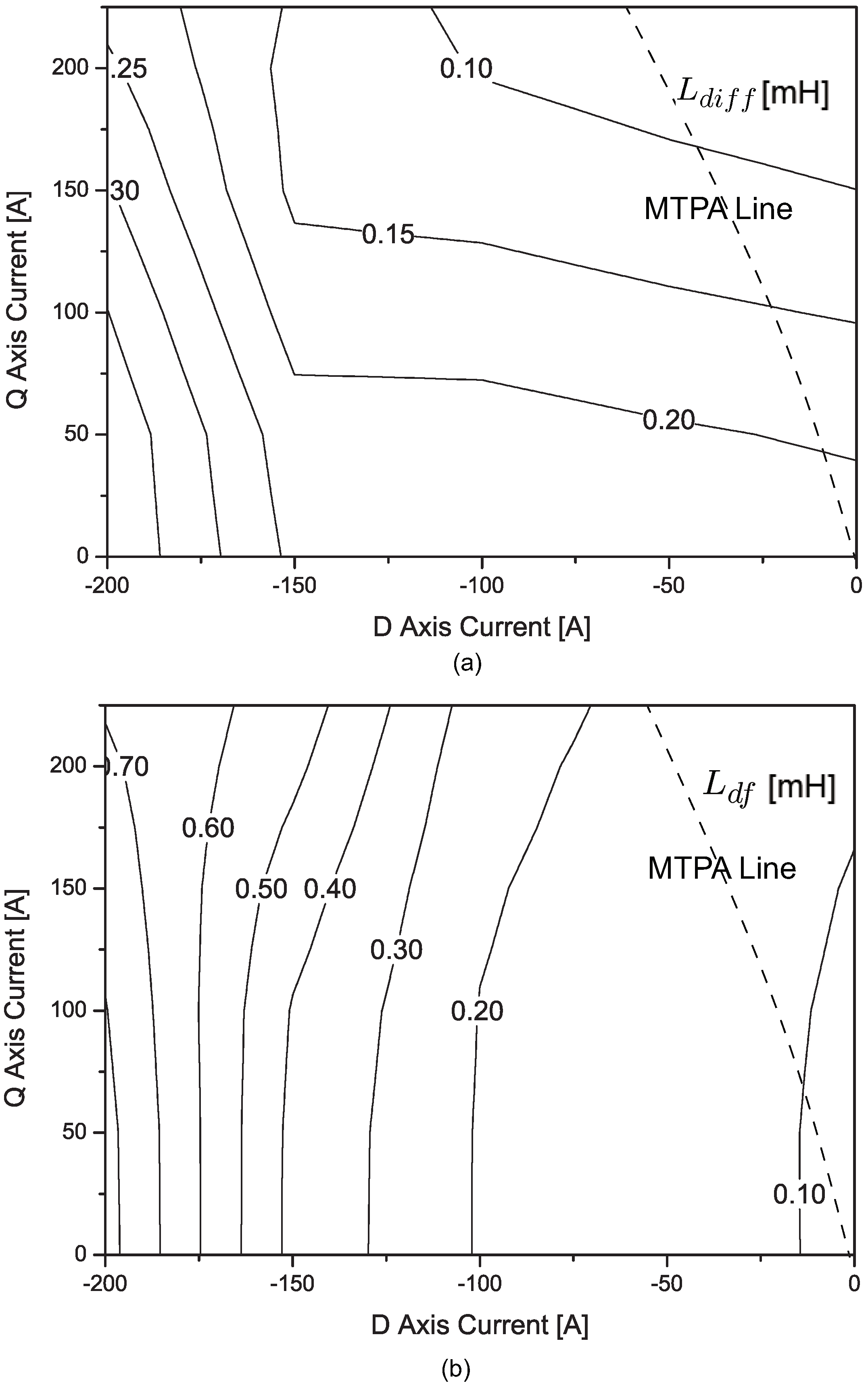
where v h is a high-frequency voltage and L d i f f = L q q t L d d t 2 . It is emphasized that L d i f f plays a crucial role in the estimation [19]. A smaller error is expected for a larger value of L d i f f .
Figure 10a shows the loci of constant L d i f f in the current plane along with the maximum torque per ampere (MTPA) line. As mentioned in the above, L d i f f decreases as i q e increases. In other words, the electromagnetic saliency ratio decreases as the load increases.
On the other hand, the proposed method does not depend on the saliency ratio. When the signal is injected into the field winding, L d f plays a similar role as L d i f f . However, its magnitude is less affected by the current magnitudes. Figure 10b shows the loci of constant L d f in the current plane. L d f increases as i d e increases negatively. Also note that L d f increases slightly when i q e increases. This can be illustrated by a small increase in L d f along with i q e as shown in Figure 6c. This supports the robust property of the field coil injection method.
According to the saliency-based method, the angle error is recovered from the term sin ( 2 Δ θ e ) . Because “2” is multiplied with Δ θ e , polarity check should be carried out. Therefore, before starting the saliency-based sensorless algorithm, a polarity-checking procedure needs to be performed. However, the angle error is estimated from sin ( Δ θ e η ) with the field current injection method; therefore, no polarity-checking step is necessary.
Another advantage is that the field current injection method does not undermine the PWM duty of an inverter, which should be used for motor operation. Normally with the stator injection method, approximately 50 Vpeak is used for high-frequency injection for a proper SNR in a 300 V dc-link inverter. However, for the field current injection method, a high-frequency signal is synthesized in a separate dc-dc converter.
For implementation, the field current injection method requires a DSP-based dc-dc converter which can produce a high-frequency signal with a dc bias. Two methods are compared in Table 2.

6. Experimental Results

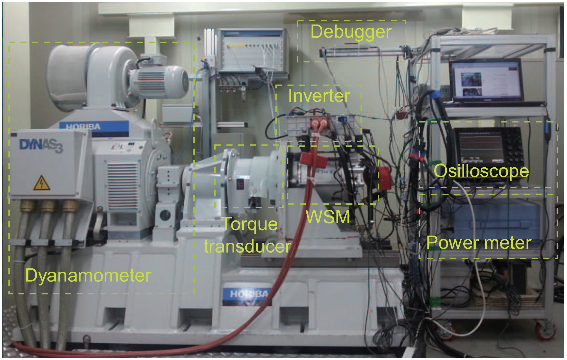
Figure 11 shows the experimental environment consisting of a dynamometer, a test WSM, an inverter, a dc to dc converter to supply the field current, etc. A zero-voltage switching (ZVS) full-bridge topology was used in the dc to dc converter, and operated at 50 kHz. As shown in Figure 12, the inverter dc-link voltage is 360 V and shared with the dc-dc converter. Practically, the field inductance is very large, and the bandwidth of field winding is very low. Consequently, it is difficult for some WSMs to inject high-frequency signal to the field winding. However, the field current supplier (DC-DC converter) is directly connected to the high voltage dc-link of the inverter.Therefore, it is enough to inject the high-frequency signal into the field winding. A carrier signal of 500 Hz, 90 V (peak-to-peak) was superposed on a dc output, which generated a 25 mA (peak-to-peak) current ripple on the dc component, i f = 6 A. In truth, it cannot be guaranteed that I h is a constant in the whole operation region due to the inductance variations from (9). Fortunately, the impedance between d-axis and rotor winding was not significantly changed in the MTPA operation. Therefore, it may have a small impact on the position estimation. The dynamometer governed the shaft speed, and the WSM was operated in the torque control mode. A Freescale MPC5554 was used as a processor for the inverter control board, and the inverter switching frequency was 8 kHz. The real angle was monitored using a resolver mounted on the WSM shaft.
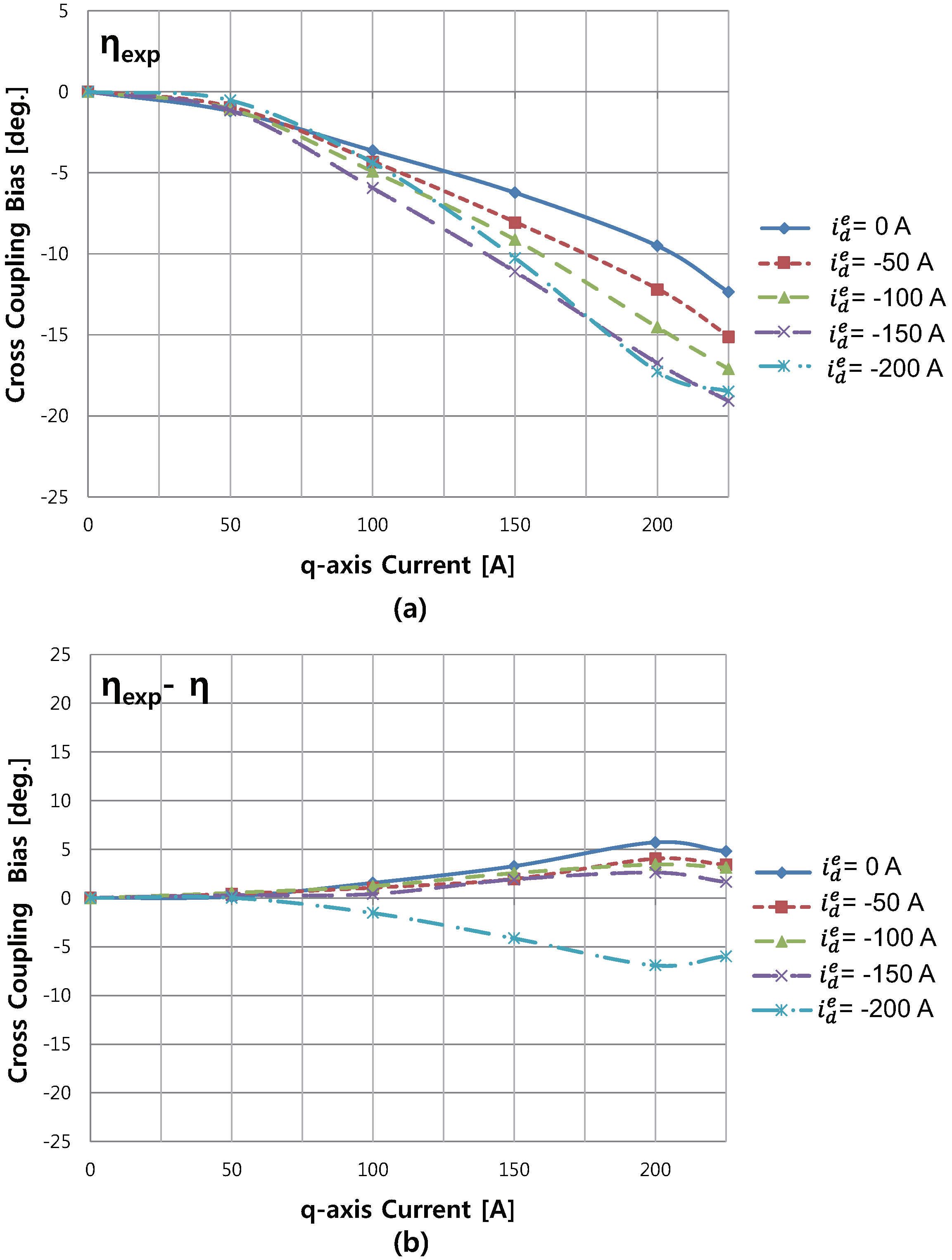
The cross-coupling bias angle η is changed depending on the load condition. The bias angle can be directly measured by simple experimental method. The motor was controlled using the real rotor angle from a resolver when the carrier signal is injected into the rotor field. Using the d q -axes currents in the misaligned frame, the estimated angle θ ^ e can be obtained without the compensation method. Then, the angle offset can be measured by η e x p = θ ^ e θ e . Figure 13a shows the experimental results of the cross-coupling bias angle. Figure 13b shows η e x p and its differences, η e x p η , from the ones computed using the FEM data. Please note that the maximum difference is approximately 6 ° (ele. degrees).
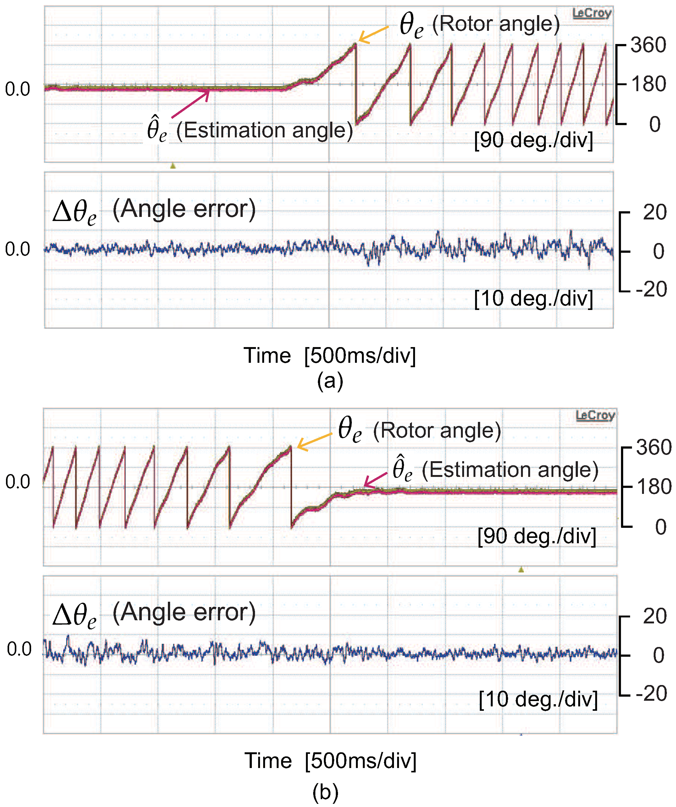
Figure 14 shows the angle estimate θ ^ e , measured angle θ e , and their difference Δ θ e = θ ^ e θ e during the transitions between 0 to 50 r/min and 50 r/min to 0 r/min, when a 28 Nm shaft torque is applied. Please note that the angle error was bounded under ± 3.33 ° (mechanical angle).
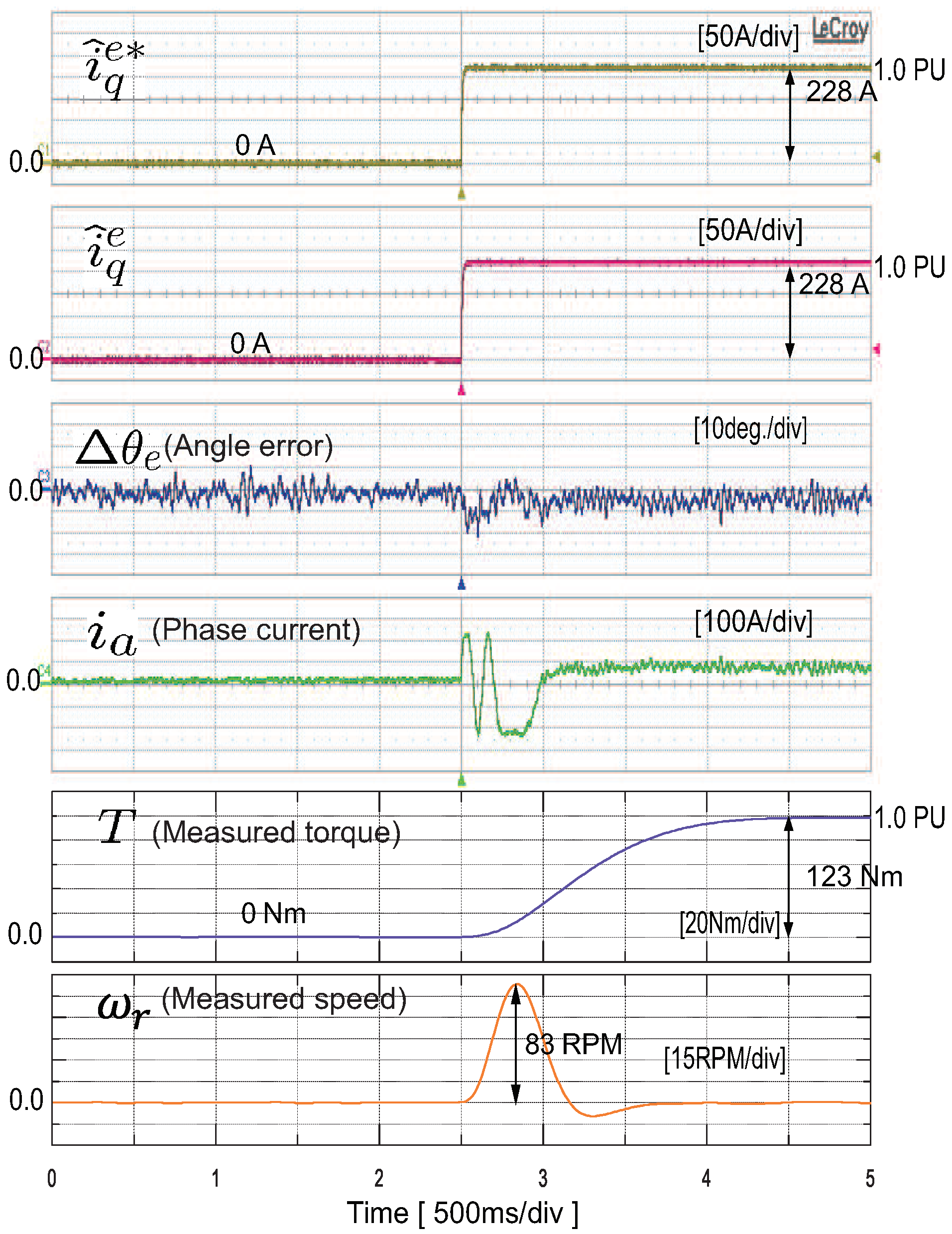
Figure 15 shows the current response to a step command i q e * = 228 A when i d e = 10 A when the motor speed was regulated at a standstill by the dynamometer motor, showing that 123 Nm (1 pu) was produced. However, the torque response appears sluggish owing to a strong filter in CAN communication. Please note that the angle error was regulated below 20 ° (ele. degrees) under a rated step torque.
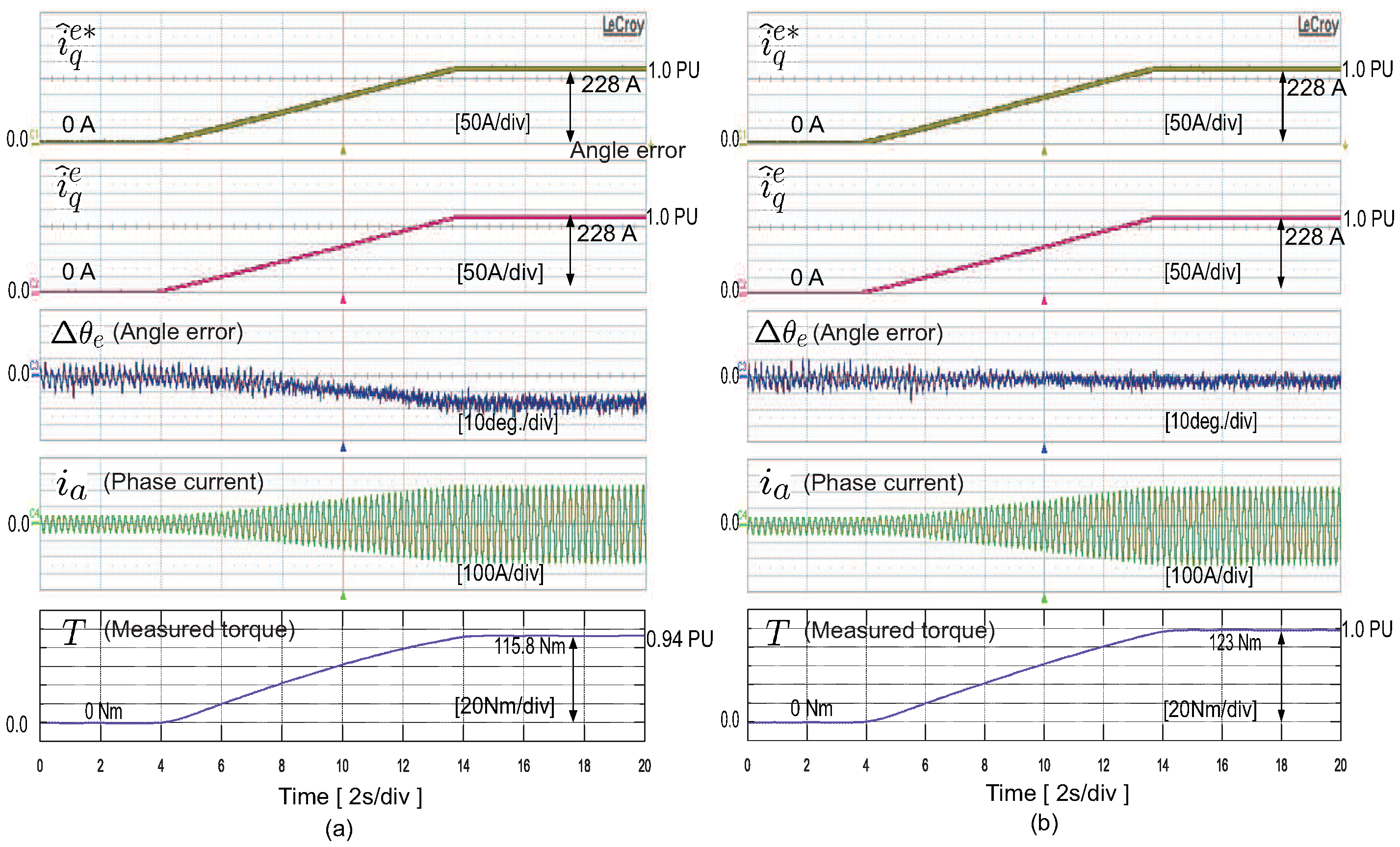
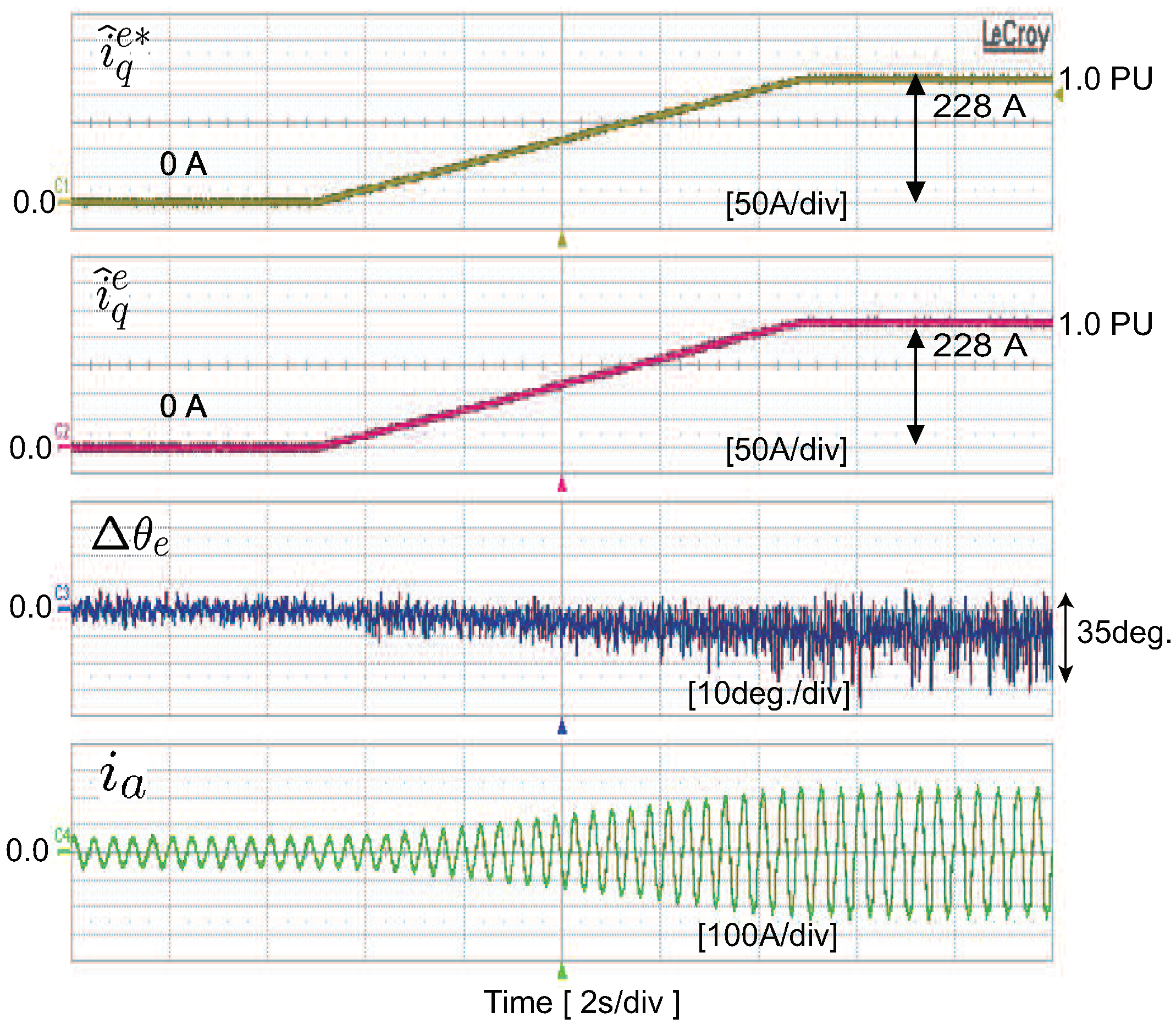
Figure 16 shows the angle error trend at a fixed speed (100 r/min) when the q-axis current increases to a rated point without and with compensation for η , which was caused by cross-coupling. The effectiveness of the cross-coupling compensation was demonstrated, in which the bias error ( 14 ° ele. degrees) was monitored without the compensation method whereas no bias error was observed with the compensation method.
Figure 17 shows the experimental result using sensorless control based on signal injection into stator winding. The dyanamometer regulated the WSM speed at 50 r/min. For a light load, the estimated angle error Δ θ e is not over 10 ° (ele. degrees). However, for a heavy load, the estimated angle error is oscillated between 30 ° and 5 ° (ele. degrees) owing to magnetic saturation.

7. Discussion

This study has attempted to investigate sensorless control for a WSM based on signal injection into the field winding. To conclude, we summarize the following contributions of the paper. The sensorless method, which injected a carrier signal into field winding, is not based on the saliency ratio. Therefore, the method does not become unstable caused owing to magnetic saturation phenomenon. In addition, the absolute position angle can be obtained. Both d- and q-axis high-frequency signals were used for angle estimation. Mutual incremental inductances are used to predict and compensate the angle offset caused by the cross-coupling effect. In this work, L d f and L q f are significant factors. The algorithm was developed to eliminate the estimation bias caused by the cross-coupling inductance. Experiments were performed for full-torque operation. Furthermore, we obtained an accurate estimated angle in the presence of the cross-coupling effect.

Author Contributions

J.C. and K.N. designed the proposed sensorless algorithm for WSM and J.C. did the experiments and analyzed the data.

Funding

This research received no external funding.

Conflicts of Interest

The authors declare no conflict of interest.

Abbreviations

The following abbreviations are used in this manuscript:
v d e , v q e d and q-axes voltage in the synchronous frame
i d e , i q e d and q-axes current in the synchronous frame
i f Field current
λ a , λ b , λ c Phase a, b, c stator flux linkage
λ d e , λ q e d and q-axes stator flux linkage in the synchronous frame
r s Stator winding resistance
L d d , L q q d and q-axes self-inductance
L d q , L q d d and q-axes cross-coupling inductance
L d f Mutual inductance between d-axis and field coil
L q f Cross-coupling inductance between q-axis and field coil
L l s Leakage inductance of stator
L l f Leakage inductance of field
θ e Rotor flux angle
θ ^ e Estimation rotor flux angle
Δ θ e Estimation rotor flux angle error
ω e , ω r Electrical speed and mechanical speed
ω h Angular speed of the carrier signal
η Angle offset caused by the cross-coupling
η c o m Compensation for angle offset
Δ θ ^ e The input of the PLL
TShaft torque
WSMWound Synchronous Machine
EVElectrical vehicles
HEVHybrid EVs
PMSMsPermanent-magnet synchronous motors
NdNeodymium
DyDysprosium
EMFElectromotive force
MTPAMaximum torque per ampere
FEMFinite-element method
LPFLow pass filter
BPFBand-pass filter

References

  1. Santiago, J.D.; Bernhoff, H.; Ekergard, B.; Eriksson, S.; Ferhatovic, S.; Waters, R.; Leijon, M. Electrical Motor Drivelines in Commercial All-Electric Vehicles: A Review. IEEE Trans. Veh. Technol. 2013, 61, 475–484. [Google Scholar] [CrossRef]
  2. Kim, Y.; Nam, K. Copper-Loss-Minimizing Field Current Control Scheme for Wound Synchronous Machines. IEEE Trans. Power Electron. 2017, 32, 1335–1345. [Google Scholar] [CrossRef]
  3. Friedrich, G.; Girardin, A. Integrated starter generator. IEEE Trans. Ind. Appl. Mag. 2009, 15, 26–34. [Google Scholar] [CrossRef]
  4. Wang, Y.; Wang, X.; Xie, W.; Dou, M. Full-Speed Range Encoderless Control for Salient-Pole PMSM with a Novel Full-Order SMO. Energies 2018, 11, 2423. [Google Scholar] [CrossRef]
  5. Morimoto, S.; Kawamoto, K.; Sanada, M.; Takeda, Y. Sensorless control strategy for salient-pole PMSM based on extended EMF in rotating reference frame. IEEE Trans. Ind. Appl. 2002, 38, 1054–1061. [Google Scholar] [CrossRef]
  6. Chen, G.-R.; Yang, S.-C.; Hsu, Y.-L.; Li, K. Position and Speed Estimation of Permanent Magnet Machine Sensorless Drive at High Speed Using an Improved Phase-Locked Loop. Energies 2017, 10, 1571. [Google Scholar] [CrossRef]
  7. Wang, M.-S.; Tsai, T.-M. Sliding Mode and Neural Network Control of Sensorless PMSM Controlled System for Power Consumption and Performance Improvement. Energies 2017, 10, 1780. [Google Scholar] [CrossRef]
  8. Genduso, F.; Miceli, R.; Rando, C.; Galluzzo, G.R. Back EMF Sensorless-Control Algorithm for High-Dynamic Performance PMSM. IEEE Trans. Ind. Electron. 2010, 57, 2092–2100. [Google Scholar] [CrossRef]
  9. Lee, J.; Hong, J.; Nam, K.; Ortega, R.; Praly, L.; Astolfi, A. Sensorless Control of Surface-Mount Permanent-Magnet Synchronous Motors Based on a Nonlinear Observer. IEEE Trans. Power Electron. 2010, 25, 290–297. [Google Scholar] [Green Version]
  10. Choi, J.; Nam, K.; Bobtsov, A.A.; Pyrkin, A.; Ortega, R. Robust Adaptive Sensorless Control for Permanent-Magnet Synchronous Motors. IEEE Trans. Power Electron. 2017, 32, 3989–3997. [Google Scholar] [CrossRef]
  11. Koteich, M.; Maloum, A.; Duc, G.; Sandou, G. Observability analysis of sensorless synchronous machine drives. In Proceedings of the 2015 European Control Conference (ECC), Linz, Austria, 15–17 July 2015; pp. 3560–3565. [Google Scholar]
  12. Tian, L.; Zhao, J.; Sun, J. Sensorless Control of Interior Permanent Magnet Synchronous Motor in Low-Speed Region Using Novel Adaptive Filter. Energies 2016, 9, 1084. [Google Scholar] [CrossRef]
  13. Gabriel, F.; De Belie, F.; Neyt, X.; Lataire, P. High-Frequency Issues Using Rotating Voltage Injections Intended For Position Self-Sensing. IEEE Trans. Ind. Electron. 2013, 60, 5447–5457. [Google Scholar] [CrossRef] [Green Version]
  14. Wu, X.; Wang, H.; Huang, S.; Huang, K.; Wang, L. Sensorless Speed Control with Initial Rotor Position Estimation for Surface Mounted Permanent Magnet Synchronous Motor Drive in Electric Vehicles. Energies 2015, 8, 11030–11046. [Google Scholar] [CrossRef] [Green Version]
  15. Gong, L.M.; Zhu, Z.Q. Robust Initial Rotor Position Estimation of Permanent-Magnet Brushless AC Machines With Carrier-Signal-Injection-Based Sensorless Control. Trans. Ind. Appl. 2013, 49, 2602–2609. [Google Scholar] [CrossRef]
  16. Li, Y.; Zhu, Z.Q.; Howe, D.; Bingham, C.M. Modeling of Cross-Coupling Magnetic Saturation in Signal-Injection-Based Sensorless Control of Permanent-Magnet Brushless AC Motors. IEEE Trans. Mag. 2007, 43, 2552–2554. [Google Scholar] [CrossRef] [Green Version]
  17. Zhu, Z.Q.; Gong, L.M. Investigation of Effectiveness of Sensorless Operation in Carrier-Signal-Injection- Based Sensorless-Control Methods. IEEE Trans. Ind. Electron. 2011, 58, 3431–3439. [Google Scholar] [CrossRef]
  18. Li, Y.; Zhu, Z.Q.; Howe, D.; Bingham, C.M.; Stone, D.A. Improved Rotor-Position Estimation by Signal Injection in Brushless AC Motors, Accounting for Cross-Coupling Magnetic Saturation. IEEE Trans. Ind. Appl. 2009, 44, 1843–1850. [Google Scholar] [CrossRef] [Green Version]
  19. Sergeant, P.; De Belie, J.; Melkebeek, J. Rotor Geometry Design of Interior PMSMs With and Without Flux Barriers for More Accurate Sensorless Control. IEEE Trans. Ind. Electron. 2012, 59, 2457–2465. [Google Scholar] [CrossRef]
  20. Li, S.; Ge, Q.; Wang, X.; Li, Y. Implementation of Sensorless Control with Improved Flux Integrator for Wound Field Synchronous Motor. In Proceedings of the 2007 2nd IEEE Conference on Industrial Electronics and Applications, Harbin, China, 23–25 May 2007; Volume 59, pp. 1526–1530. [Google Scholar]
  21. Maalouf, A.; Ballois, S.L.; Idekhajine, L.; Monmasson, E.; Midy, J.; Biais, F. Sensorless Control of Brushless Exciter Synchronous Starter Generator Using Extended Kalman Filter. In Proceedings of the 2009 35th Annual Conference of IEEE Industrial Electronics, Porto, Portugal, 3–5 November 2009; Volume 59, pp. 2581–2586. [Google Scholar]
  22. Boldea, I.; Andreescu, G.D.; Rossi, C. Active Flux Based Motion-Sensorless Vector Control of DC-Excited Synchronous Machines. In Proceedings of the 2009 IEEE Energy Conversion Congress and Exposition, San Jose, CA, USA, 20–24 September 2009; pp. 2496–2503. [Google Scholar]
  23. Jain, A.K.; Ranganathan, V.T. Modeling and Field Oriented Control of Salient Pole Wound Field Synchronous Machine in Stator Flux Coordinates. IEEE Trans. Ind. Electron. 2011, 58, 960–970. [Google Scholar] [CrossRef]
  24. Griffo, A.; Drury, D.; Sawata, T.; Mellor, P.H. Sensorless starting of a wound-field synchronous starter/generator for aerospace applications. IEEE Trans. Ind. Electron. 2012, 59, 3579–3587. [Google Scholar] [CrossRef]
  25. Rambetius, A.; Ebersberger, S.; Seilmeier, M.; Piepenbreier, B. Carrier Signal Based Sensorless Control of Electrically Excited Synchronous Machines at Standstill and Low Speed Using The Rotor Winding as a receiver. In Proceedings of the 2013 15th European Conference on Power Electronics and Applications (EPE), Lille, France, 2–6 September 2013; pp. 1–10. [Google Scholar]
  26. Deng, X.; Wang, L.; Zhang, J.; Ma, Z. Rotor Position Detection of Synchronous Motor Based on High-frequency Signal Injection into the Rotor. In Proceedings of the 2011 Third International Conference on Measuring Technology and Mechatronics Automation, Shangshai, China, 6–7 January 2011; pp. 195–198. [Google Scholar]
  27. Zhou, Y.; Long, S. Sensorless Direct Torque Control for Electrically Excited Synchronous Motor Based on Injecting High-Frequency Ripple Current Into Rotor Winding. IEEE Trans. Energy Convers. 2015, 30, 246–253. [Google Scholar] [CrossRef]
  28. Rambetius, A.; Piepenbreier, B. Comparison of carrier signal based approaches for sensorless wound rotor synchronous machines. In Proceedings of the International Symposium on Power Electronics, Electrical Drives, Automation and Motion, Schia, Italy, 18–20 June 2014; pp. 1152–1159. [Google Scholar]
  29. Rambetius, A.; Piepenbreier, B. Sensorless control of wound rotor synchronous machines using the switching of the rotor chopper as a carrier signal. In Proceedings of the International Symposium on Sensorless Control for Electrical Drives and Predictive Control of Electrical Drives and Power Electronics, Munich, Germany, 17–19 October 2013; pp. 1–8. [Google Scholar]
  30. Choi, J.; Jeong, I.; Jung, S.; Nam, K. Sensorless Control for Electrically Energized Synchronous Motor Based on Signal Injection to Field Winding. In Proceedings of the IECON2013—39th Annual Conference of the IEEE Industrial Electronics Society, Vienna, Austria, 10–13 November 2013; pp. 3120–3129. [Google Scholar]
  31. Selmon, G.R. Electric Machines and Drives; Addison Welsley: Boston, MA, USA, 1992; ISBN 0-201-57885-9. [Google Scholar]
  32. Stumberger, B.; Stumberger, G.; Dolinar, D.; Hamler, A.; Trlep, M. Evaluation of Saturation and Cross-Magnetization Effects in Interior Permanent-Magnet Synchronous Motor. IEEE Trans. Ind. Appl. 2009, 48, 1576–1587. [Google Scholar]
  33. Nam, K.H. AC Motor Control and Electric Vehicle Application, 1st ed.; CRC Press: Boca Raton, FL, USA, 2010; ISBN 978-1-49-81963-0. [Google Scholar]
  34. Garcia, P.; Briz, F.; Degner, M.W.; Diaz-Reigosa, D. Accuracy, Bandwidth, and Stability Limits of Carrier-Signal-Injection-Based Sensorless Control Methods. IEEE Trans. Ind. Appl. 2009, 43, 990–1000. [Google Scholar] [CrossRef]
  35. De Kock, H.W.; Kamper, M.J.; Kennel, R.M. Anisotropy Comparison of Reluctance and PM Synchronous Machines for Position Sensorless Control Using HF Carrier Injection. IEEE Trans. Power Electron. 2009, 24, 1905–1913. [Google Scholar] [CrossRef]
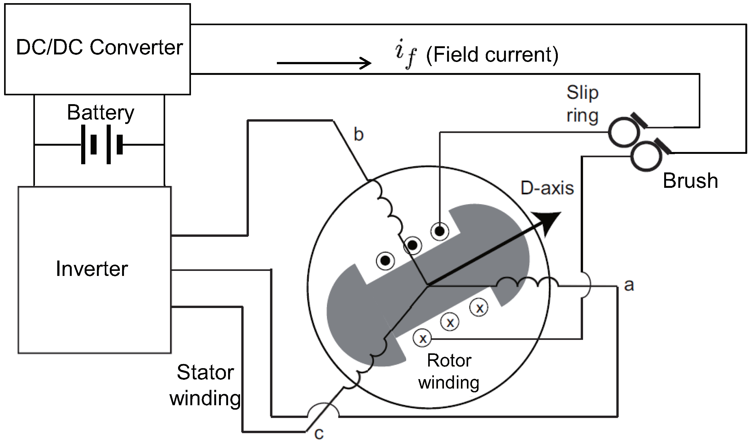
Figure 1. Schematic Diagram of WSM for EV traction.
Energies 11 03278 g001
Figure 2. Equivalent circuit of the WSM including cross-coupling inductance: (a) d-axis and (b) q-axis.
Energies 11 03278 g002
Figure 3. Flux linkage calculation when i f = 6 A: (a) Finite-element analysis model and (b) flux linkages of stator coils.
Energies 11 03278 g003
Figure 4. Flux linkages when i f = 6 A (FEM analysis): (a) 3-dimensional plot of λ d e ; (b) contour plot of λ d e ; (c) 3-dimensional plot of λ q e ; and (d) contour plot of λ q e .
Energies 11 03278 g004
Figure 5. The Influence of the field current on d q -axes stator flux linkage ( λ d e , λ q e ): (a) Contour plot λ d e , and (b) contour plot of λ d e . (solid and blue line: i f = 6 A, dash dot and magenta line: i f = 6.5 A).
Energies 11 03278 g005
Figure 6. Finite-element method (FEM) data for the self and mutual incremental inductances: (a) d-axis self-inductance L d d ; (b) q-axis self-inductance L q q ; (c) d-axis and q-axis cross-coupling inductance L d q ; (d) q-axis and d-axis cross-coupling inductance L q d ; (e) d-axis and field coil mutual inductance L d f ; and (f) q-axis and field coil cross-coupling inductance L q f .
Energies 11 03278 g006
Figure 7. Misaligned d q -frame.
Energies 11 03278 g007
Figure 8. Signal processing block based on the signal-injection method into the field winding.
Energies 11 03278 g008
Figure 9. The cross-coupling bias η calculated based on the FEM data: (a) Plot of η and (b) contour plot of η .
Energies 11 03278 g009
Figure 10. (a) L d i f f , which is important for sensorless control based on signal injection into stator and (b) L d f , which is important for sensorless control based on signal injection into rotor.
Energies 11 03278 g010
Figure 11. Experiment environment for testing sensorless control: the dynamometer, inverter, debugger, osilloscope, torque transducer, and WSM.
Energies 11 03278 g011
Figure 12. Block diagram of a proposed sensorless control method for a WSM.
Energies 11 03278 g012
Figure 13. (a) Experimental angle offset due to the cross-coupling inductance and (b) The differences between the angle offset measured η e x p and the angle offset calculated η using FEM data.
Energies 11 03278 g013
Figure 14. Proposed sensorless control during speed transitions (28 Nm, i d e = 20 A, i q e = 50 A): (a) 0 → 50 r/min and (b) 50 → 0 r/min.
Energies 11 03278 g014
Figure 15. Current responses at a standstill for a q-axis command (0 A 228 A) when i d e = 10 A: q-axis current command, q-axis current, angle error, phase current, shaft torque, and shaft speed.
Energies 11 03278 g015
Figure 16. Field current injection method (a) without compensation for η caused by cross-coupling and (b) with compensation for η : ramp q-axis command (0 A → 228 A), q-axis current response, angle error, phase current, and torque.
Energies 11 03278 g016
Figure 17. Signal injection into the stator winding without a compensation of cross-coupling effects: response at 50 r/min for a ramp q-axis command (0 A → 228 A) when i d e = 50 A.
Energies 11 03278 g017
Table 1. Parameters of a WSM used in the experiments.
ParameterValue
Maximum power65 kW
Maximum torque123 Nm
Maximum current161 Arms
Numbers of poles (P)6 poles
Number of slots36 slot
Back-EMF coefficient0.121 Wb
Maximum speed12,000 r/min
Field current ( i f )6 A
Number of stator coil turns ( N s )3 turns
Number of field coil turns ( N f d )200 turns
Table 2. Comparison between the injection methods into stator and field windings.
Signal Injection into Stator WindingSignal Injection into Field Winding
Signal amplitude L d i f f (Saliency) L d f (Mutual)
Polarity checkNecessaryNot necessary
SNR under core saturationSmallLarge
Signal generationInverterdc-dc converter
Stable region ( Δ θ e )< 45 ° < 90 °
ImplementationEasyMedium difficulty