Article

A Novel Static Correction Approach for Eliminating the Effect of Geophones—A Case Study in Coal Reservoirs, Ordos Basin, China

1
State Key Laboratory of Coal Resources and Safe Mining, China University of Mining and Technology (Beijing), Beijing 100083, China
2
College of Geoscience and Surveying Engineering, China University of Mining and Technology (Beijing), Beijing 100083, China
*
Author to whom correspondence should be addressed.
Energies 2018, 11(12), 3240; https://doi.org/10.3390/en11123240
Submission received: 9 October 2018 / Revised: 9 November 2018 / Accepted: 19 November 2018 / Published: 22 November 2018

Abstract

:
Static correction is an essential step in seismic processing and it has an effect on the later steps of seismic processing, including velocity analysis, data stacking, and seismic inversion. During seismic data acquisition, a receiving point usually sets a geophone several times to receive the seismic data. The same geophone cannot be set at the same receiving point every time. If the geophones have different delay time, then the common receiving-point gather (CRG) will have multiple receiver statics. However, the receiver statics of a CRG are considered the same in conventional static correction. In this paper, based on common attitude gather (CAG), a novel static correction method is proposed to analyze the receiver statics of a CRG. Attitude indicates the tilt angles of the three components of a geophone. According to the different attitudes of geophones, CRG can be divided into multiple CAGs. When the difference technique is used to the novel method and the conventional method, the statics are analyzed with CAGs and CRGs, respectively. A field example demonstrates that the proposed method cannot only enhance the continuity of the event in the shot gather, but also smooth the gaps of the event in the CRG. The results suggest that the proposed method can eliminate the effect of differences in delay time of geophones on static correction.

1. Introduction

Seismic prospecting is a robust technology for carbonate and coal reservoir exploration [1,2]. Static correction is an indispensable step in seismic processing and it has a severe effect on the later steps, including velocity analysis, data stacking, and imaging workflows [3,4,5]. For land seismic data acquisitions, the complex surface geologic conditions, such as weathered layers, sand dunes, and human-induced obstacles, will influence the quality of the recorded data due to the multipath of seismic waves on the surface [6]. It is really a challenge to eliminate the influence of complex surface conditions in seismic processing [6,7,8]. In fact, static correction is a practical way to effectively eliminate such influence [3,7]. The purpose of static correction is to accurately obtain the reflection time of seismic waves under the assumption that the seismic data are recorded on a datum plane [7,9].
In past decades, many different methods [5,8,10,11,12,13,14,15,16,17,18,19,20,21,22,23,24,25,26,27] have been proposed to deal with the problem of static correction. Surface consistency and nonsurface consistency static correction are two effective approaches [12,14,20,21,26,27]. Surface consistency static correction shows that the effect on static correction from the near-surface only depends on the position of the receiver (or source), but it is independent of the offset (distance from source point to receiver point) or the recorded time of the seismic data [12]. The traces in a common receiving-point gather (CRG) have the same receiver statics [3,10,11,12]. Surface consistency static correction contains two kinds of approaches: field static correction and residual static correction [11,14,20,21,22,23,24,25]. The methods based on field static correction, such as model static correction [13], refraction static correction [14,15,16,17], and tomographic static correction [18,19], can compensate the time changes due to the variation of velocity and elevation at the near-surface [14,15,16,17,18,19]. Residual static correction has attracted attention and many papers [20,21,22,23,24,25] have been published, including the stack-power maximization method [23], generalized linear inversion method [5,24], and simulated annealing method [25]. When compared with surface consistency static correction, nonsurface consistency static correction focuses on the strong changes of velocity in the lateral direction and elevation of the near-surface, which do not obey the assumptions of surface consistency static correction [3,26,27]. For nonsurface consistency static correction, floating datum static correction is used to compensate the delay time in the presence of strong changes of velocity and elevation in the pre-stack domain, and then nonsurface consistency residual static correction is applied to compensate the residual delay time [26,27].
However, it is usual that a geophone will be set at the same location several times in seismic acquisitions. The same geophone may not be placed at the same location each time. If the geophones have different delay time because of damage and aging, the receiver statics of a CRG will no longer be unique, which violates the assumption of surface consistency and it deviates from the application conditions of nonsurface consistency static correction. The purpose of this study is to put forward a solution to the problem mentioned above. In order to solve the problem, traces that are received by the same geophone at a receiving point are considered as a CAG. The difference technique was used to obtain the receiver statics of CAGs. Then, a field example is provided to test the new method of eliminating the effect of geophones on static correction.

2. Theory and Methodology

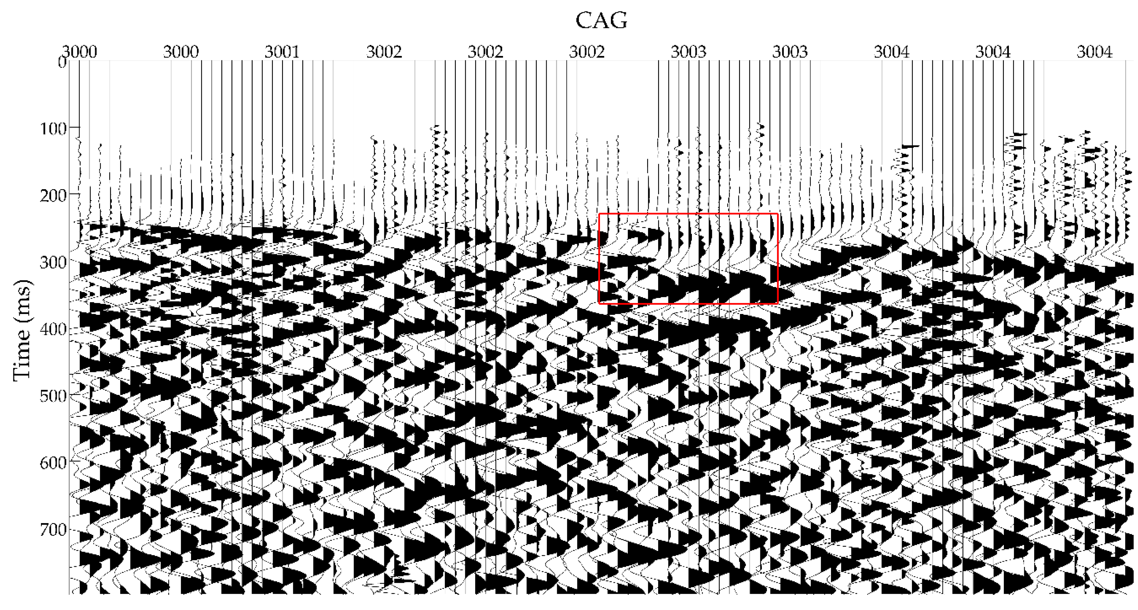
2.1. Common Attitude Gathers (CAGs)

For three-dimensional and three-component (3D3C) field seismic acquisition, thousands of seismic sources are distributed in an exploration area. A geophone semiburied at a location will receive reflections from part of the seismic sources. Traces are recorded at a receiving point, named a CRG [28]. In fact, setting different geophones at the same receiving point during seismic acquisition is usual occurrence. The attitudes of the geophones can be used to distinguish which geophone receives the trace at the receiving point. The seismic traces received by one geophone are considered to be a CAG. The attitude indicates the tilt angles of the three components of the geophone at a receiving point. The tilt angle of each component can be acquired through gravity testing by the acquisition equipment [29]. Based on the differences in the attitudes of the geophones, CAGs are extracted from the CRG. The CAGs can be considered as subsets of the CRGs. There is a different attitude for each geophone at the same receiving point. Three main factors leading to the attitude change are found by analyzing the 3D3C land seismic data acquisition. First, the attitude of a geophone can be affected by an external force. For instance, bushes draw geophones to a different orientation through cables when the wind flows during land exploration. Second, seismic data acquisition is implemented in accordance with the geometry to achieve a uniform fold. As shown in Figure 1a, seismic data acquisition occurs from pattern 1 to pattern 6, which clearly contains an overlapping area. A receiving point will set the geophone more than once in this overlapping area. Figure 1b shows a pattern in Figure 1a and it shows that the attitudes of the geophones are different. Additionally, a large number of geophones are used for seismic data acquisition. It is hard to ensure that the same geophone with a certain attitude will be reset at the same receiving point, which is costly and time-consuming. Thus, the attitudes of the geophones will inevitably be changed at the same receiving point. Third, in practice, seismic data acquisition cannot be completed in one day. The geophones need to be withdrawn at night and reset the next day for the security of property. As a result, the attitudes of geophones will be changed at the same receiving point.
For the above first factor, the coupling relationship between the geophone and the near-surface will differ with the variation of attitude, and the first factor will affect the amplitude and polarization attributes of the seismic data based on previous studies [29,30]. The present study considers that the first factor may lead to an unequal delay time and will cause the problem of static correction.
In fact, geophones are corrected in the factory to make the delay time and sensibility equal. The delay time and sensibility of geophones will change over time due to damage and aging. Thus, for the second and third factors, the delay time at the same receiving point will be unequal due to the changes in the geophones. The factors that cause variations in the delay time will lead to the problem of static correction.

2.2. Static Correction Methodology Based on CAGs

The refraction method of static correction allows us to obtain the thicknesses of the near-surface, the velocity of the near-surface, and the refraction velocity by handling the first breaks of seismic data [14]. The application condition of refraction static correction is that the refraction interface is relatively stable [31]. Liu (2015) and Du (2017) studied the near-surface velocity and thickness model of the field example. The results indicate that the field example satisfies the application condition of refraction static correction [17,32]. For the conventional refraction static correction method, which is based on CRGs, traces have the same receiver statics in a CRG [14,17,32]. However, geophones may have different delay time when being used to record seismic data at a receiving point, which change the receiver statics in a CRG. To deal with the problem, a new method of refraction static correction that is based on CAGs is proposed.
CAGs are subsets of CRGs, and the statics of each gather should be coupled with other gathers. It is expensive to use the methods that are based on CRGs to obtain the statics of the shots and receivers [33]. Linear move-out (LMO) is a suitable measure for testing the effects of static correction [7]. After the application of LMO, the first breaks will be linear with the offset when the static correction is accurate [33]. For adjacent seismic traces in a shot gather, the difference of the first breaks is equal to the difference of the receiver points’ statics. For the seismic traces in a CAG, the difference of the first breaks is equal to the difference of the shot points’ statics. After the LMO, the first breaks of the adjacent seismic traces in a CAG are written, as follows [34]:
{ t 1 ¯ = t 1 x 1 / V t 2 ¯ = t 2 x 2 / V t 3 ¯ = t 3 x 3 / V t n ¯ = t n x n / V .
where X = x 1 , x 2 , , x n (m) are the offsets of the adjacent seismic traces in the CAG; T = t 1 , t 2 , , t n (s) are the first breaks of the adjacent seismic traces in the CAG; the velocity of the LMO is V (m/s); and, T ¯ = t 1 ¯ , t 2 ¯ , , t n ¯ (s) are the time difference of the LMO. To briefly derive the difference scheme, n = 9 is defined. Then, the differences of the shot points’ statics are as follows:
{ Δ 1 = t 2 ¯ t 1 ¯ Δ 2 = t 3 ¯ t 2 ¯ Δ 3 = t 4 ¯ t 3 ¯ Δ 8 = t 9 ¯ t 8 ¯ .
Respectively multiplying Equation (2) by 1, 2, 3, 4, 4, 3, 2, and 1 and adding the first four terms obtains Equation (3), which is as follows:
Δ 1 + 2 Δ 2 + 3 Δ 3 + 4 Δ 4 = t 1 ¯ t 2 ¯ t 3 ¯ t 4 ¯ + 4 t 5 ¯ .
Adding the last four terms of Equation (2) obtains Equation (4), which is shown as
Δ 8 + 2 Δ 7 + 3 Δ 6 + 4 Δ 5 = t 6 ¯ + t 7 ¯ + t 8 ¯ + t 9 ¯ 4 t 5 ¯ .
Subtracting Equation (3) from Equation (4) with further simplification, the result is:
( Δ 8 Δ 1 ) + 2 ( Δ 7 Δ 2 ) + 3 ( Δ 6 Δ 3 ) + 4 ( Δ 5 Δ 4 ) = j = 1 9 t j ¯ 9 t 5 ¯ .
where j   ( 1 j n ) denotes the number of adjacent seismic traces and j is an odd number. If the near-surface is smooth, then the sum of the shot points’ statics will be equal to zero. Thus, j = 1 9 t j ¯ 0 . As a result, the statics of the middle shot point is as follows:
t 5 ¯ 1 9 j = 1 j = 4 j ( Δ 9 j Δ j ) .
The number of adjacent seismic traces is based on the geological conditions. Therefore, the difference scheme can be expressed, as follows:
t ¯ ( n 1 ) / 2 1 n j = 1 j = n 1 2 j ( Δ n j Δ j ) .
Finally, the shot points’ statics can be achieved. Similarly, the receiver points’ statics can be obtained in the shot gathers that are based on the CAGs.

3. Field Data Acquisition and Processing
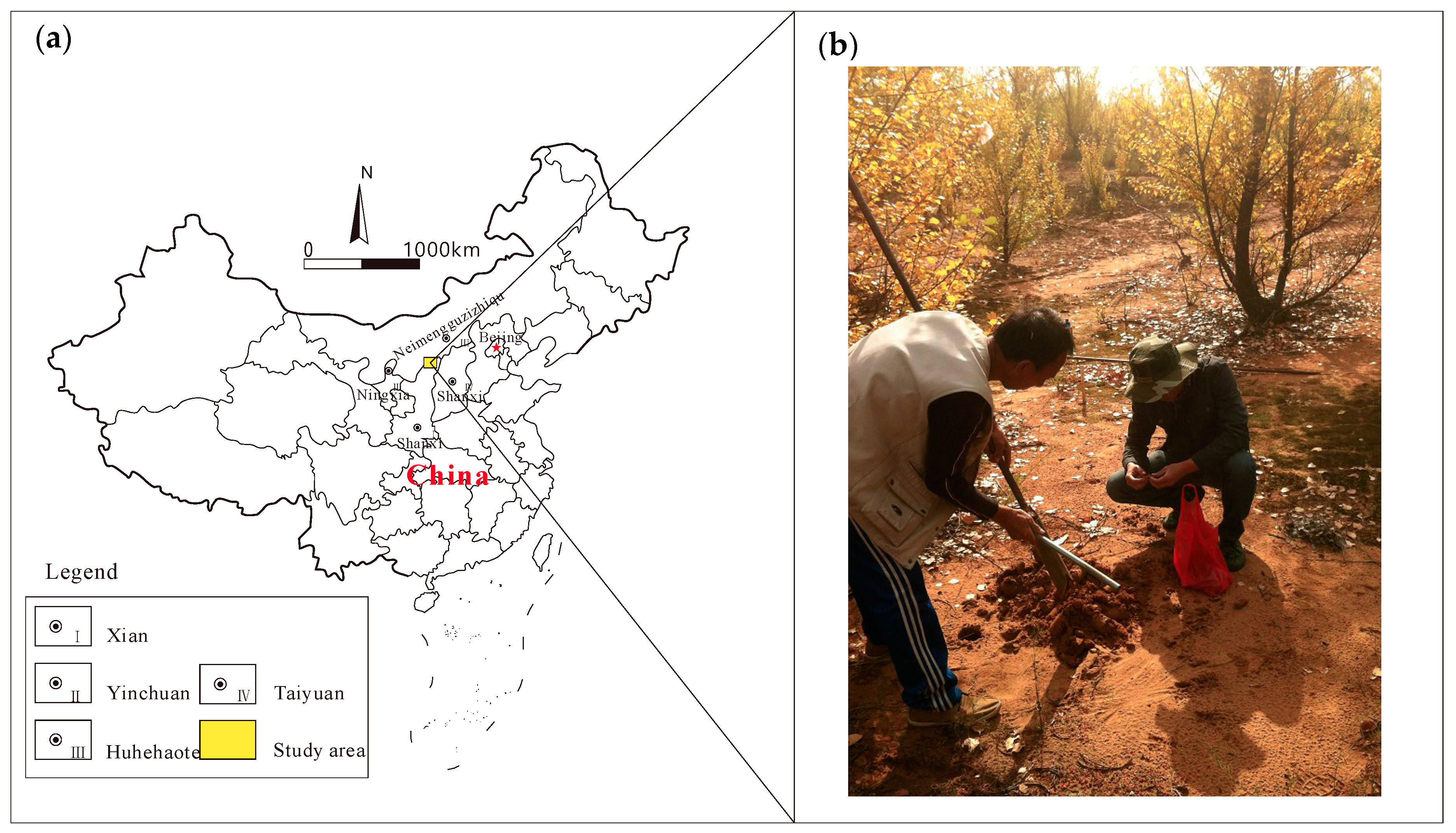
3.1. Study Area

In recent years, many papers [17,32,35,36,37,38,39] have been published about the Ordos Basin, China, and this area has become a hotspot. In this paper, field data are derived from the Daliuta Coal Mine (Figure 2) at Yulin city, Shanxi Province, China, which is located at 39°13′53″–39°21′32″ N, 110°12′23″–110°22′54″ E. The Daliuta Coal Mine lies in the north of the Loess Plateau and southeast of the Maowusu Desert, Ordos Basin, China. The total area of the study area is 1.2 km2. Part of the near-surface is covered by bushes and this area is usually windy, which easily damages the attitude of the geophones. The temperature difference in this area between day and night is from 24° to −16° in October. It is hard to insert the geophones in the topsoil due to the frozen soil in the morning, and then the topsoil becomes soft with the increase of temperature at noon. The geophones fall over easily because of the melting of frozen soil [29].
Table 1 shows the strata of this area and indicates that unconsolidated Quaternary strata are distributed above the coal seam and the overlying strata thickness is about 250 m. According to geological data from this area, magmatism and tectonism are inactive, the stratigraphic structure is fine, the thickness of the target coal seam is approximately 7 m, and the dip angle of the target coal seam is about 1°–3°.

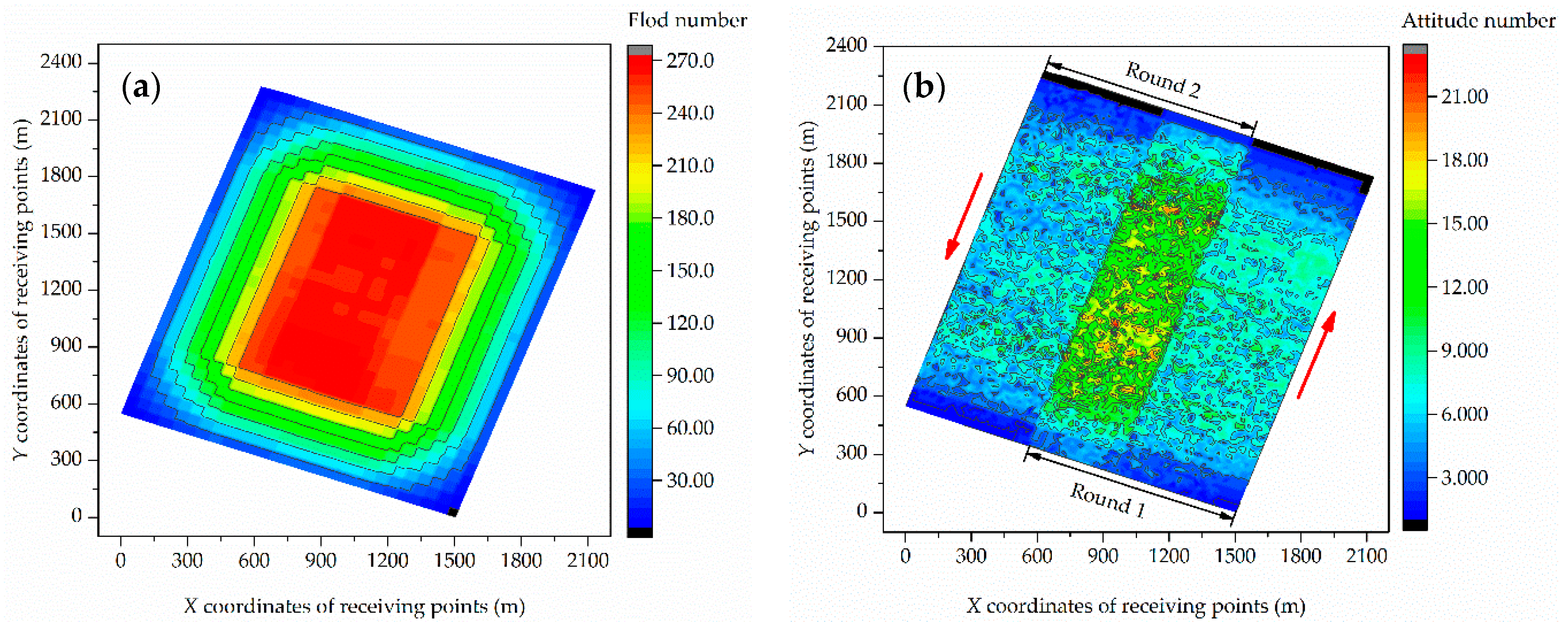
3.2. Data Acquisition and Processing

In seismic data acquisition, DSU3 three-component geophones from Sercel, France, were used to receive seismic waves. These geophones had been used for more than three years. Data acquisition was from 5–11 October 2013 and it was windy. The geometry of the seismic data acquisition had 24 receiver lines, 24 traces in a receiver line, and 2 × 2 shot square layout. The distance between receiver points was 20 m in both directions, and the distance between shot points was 30 m. The minimum distance between shot points to receiver points was 7.07 m and the maximum distance between shot points and receiver points was 346.48 m. The primary parameters of the geometry are presented in Table 2.
According to the geometry of the seismic data acquisition in Table 2, seismic acquisition of the study area was finished. The practical folds are shown in Figure 3a. It is obvious that there are 60–250 folds for the majority of the study area. The maximum number of folds, greater than 200, are located in the central area. There are only 0–60 folds in the edge area. The folds gradually decrease from the location of the maximum value in the central area to the edge area. The Sercel DSU3 geophones can accurately record changes of attitude during seismic acquisition. Thus, the attitudes of geophones at each receiving point can be extracted, which are shown in Figure 3b. There are three distinct strips from the northeast to the southwest. The number of attitudes in the middle strip is almost 10–20 and in the other strips is mainly 1–10. There are twice as many attitudes in the middle strip as in the other strips. According to the acquisition log, analyzing the process of seismic acquisition sheds light on this phenomenon. The acquisition process can be divided into two rounds, as shown in Figure 3b. Round 1 began on 5 October and ended on 10 October 2013, and the direction was from southeast to northeast. Round 2 began on 11 October and ended on 15 October 2013, and the direction was from northwest to southwest. There is an overlapping area (the middle strip) in this acquisition area. It is inevitable that the geophones in the middle strip are set twice as often as the other strips.
The near-surface velocity and refraction velocity were obtained by analyzing the first breaks. The shot gather (No. 624) and the CRG (No. 825) after the LMO, with a delay time of 200 ms each, are shown in Figure 4 and Figure 5. The event near 260 ms is not smooth and continuous enough in the shot gather, as shown by a red ellipse in Figure 4. In Figure 5, the event near 260 ms is not aligned in the CRG and the gaps between the event are clearly visible, as shown by the red rectangle. There are five attitudes of geophones in the CRG, which indicates that there are five CAGs. The identifiers of the CAGs are 3000, 3001, 3002, 3003, and 3004. Section 4.1 and Section 4.2 provide detailed analyses of solving the static correction with the CRGs and CAGs, respectively.

4. Results

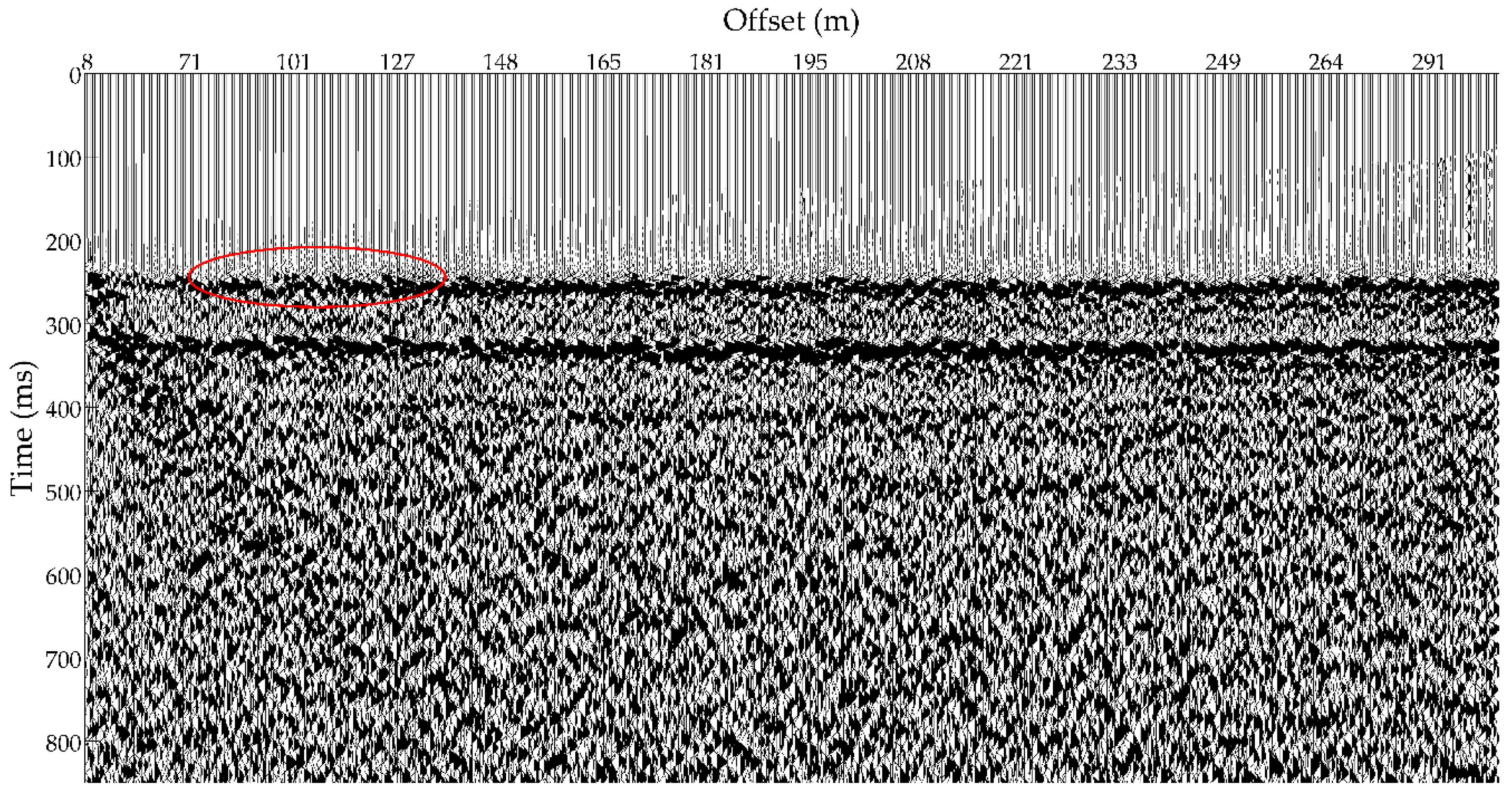
4.1. Static Correction Methodology Based on CRGs

In order to compare with the proposed method in this paper, the static correction method based on CRGs was applied to the 3D3C field data. In addition, the difference technique was used to obtain the statics of the corresponding receivers and shots, which can effectively save computational cost. The shot gather (No. 624) and the CRG (No. 825) after application of the LMO, with a delay time of 200 ms, are shown in Figure 6 and Figure 7, respectively. Compared with the event near 260 ms in Figure 4, it is evident that the continuity of the event is enhanced and the event is much smoother in Figure 6. Comparing Figure 7 with Figure 5, the gaps between the event of interest are further reduced to some extent. However, the event of interest does not appear flat in the CRG gather. These traces with delay time will still severely influence the following processing steps.

4.2. Static Correction Methodology Based on CAGs

To eliminate the effect of the geophone’s delay time on the static correction, the static correction that is based on CAGs was used for the 3D3C field seismic data. The difference technique and the LMO are used for the field data. Figure 8 and Figure 9 show the shot gather (No. 624) and the CRG (No. 825) with a delay time of 200 ms, respectively. Comparing Figure 8 with Figure 6, the event near 260 ms is much smoother and more continuous, as shown by the red ellipse. In Figure 9, the event of interest is aligned and the gaps in the event of interest are almost filled. Thus, the new method considering the effect of the geophone’s attitude can clearly improve the accuracy of the static correction. The results suggest that the proposed method that is based on CAGs for static correction is effective in enhancing the continuity of events and eliminating the delay time.

5. Conclusions

During seismic acquisition, a receiving point usually sets a geophone several times to receive seismic data. The same geophone cannot be placed at the same receiving point every time. If the geophones have different delay time because of damage and aging, this will lead to the problem of static correction. However, the conventional methods are designed to correct the error that is caused by the complex near-surface and are inappropriate to solve the problem of static correction. In this paper, a novel static correction method that is based on CAGs is proposed to deal with the problem. The attitude indicates the tilt angles of the three-component geophone. The attitudes of geophones are used to distinguish which geophone receives the trace at the same receiving point. The seismic traces that are received by the same geophone are considered as a CAG. Then, the difference technique is used to obtain the unique receiver statics of the CAGs. The 3D3C field example indicates that setting different geophones at a receiving point during seismic acquisition will lead to the problem of static correction and cannot be ignored in seismic prospecting. When compared with the method based on CRGs, the results suggest that the novel method is effective in enhancing the continuity of event and eliminating the effect of geophones on static correction. The new method can provide promising results and has great potential for further data processing.
In this paper, CAGs are extracted from CRGs according to the different attitudes of geophones. The attitude information is the tilt angles of the three components of the geophone. Benefited from the advanced three-component DSU3 geophone from Sercel, France, the tilt angle of each component can be acquired through gravity testing. However, the geophones’ attitudes usually lack seismic data. For example, compression wave prospecting cannot provide the tilt angle of the geophone. It is a challenge to extract CAGs from CRGs, therefore further research will be needed. While, the layout time of geophones at each receiving point can be found according to the acquisition log, and then CAGs can be extracted from CRGs. Thus, how to effectively extract CAGs from CRGs without the attitude information will be the focus in the future.

Author Contributions

L.S., S.P., and D.H. are equal contributors to this work.

Funding

This research was funded by the China National Key Research and Development Program (2016YFC0501102), the Coal United Project of National Natural Science Foundation (U1261203), and the National Natural Science Foundation of China (41504041).

Acknowledgments

Thanks to Peng Research Group of CUMTB for their support of this research, and thanks to Wenfeng Du for practical support in this study. Furthermore, thanks to Yongxu Lu, Peng Lin, and Jingtao Zhao for their meaningful discussions and helpful suggestions.

Conflicts of Interest

The authors declare no conflicts of interest.

Nomenclature

YAdjacent seismic traces in common attitude gathers
XDistance from shot point to receiver point (m)
TFirst break (s)
T ¯ Time difference of the LMO (s)
VNear-surface velocity or refraction velocity (m/s)
jNumber of adjacent seismic traces
nTotal number of adjacent seismic traces

Abbreviations

3D3CThree-dimensional and three-component
CAGCommon attitude gather
CRGCommon receiving-point gather
LMOLinear move-out
No.Number

References

  1. Fang, J.L.; Zhou, F.D.; Tang, Z.H. Discrete Fracture Network Modelling in a Naturally Fractured Carbonate Reservoir in the Jingbei Oilfield, China. Energies 2017, 10, 183. [Google Scholar] [CrossRef]
  2. Lu, J.; Wang, Y.; Chen, J.Y. Detection of Tectonically Deformed Coal Using Model-Based Joint Inversion of Multi-Component Seismic Data. Energies 2018, 11, 829. [Google Scholar] [CrossRef]
  3. Deere, J.; Cox, M. Introduction to This Special Section—Statics. Lead. Edge 2009, 28, 190–191. [Google Scholar] [CrossRef]
  4. Raef, A. Land 3D-seismic Data: Preprocessing Quality Control Utilizing Survey Design Specifications, Noise Properties, Normal Moveout, First Breaks, and Offset. J. Earth Sci. China 2009, 20, 640–648. [Google Scholar] [CrossRef]
  5. Zhu, X.; Gao, R.; Li, Q.S.; Guan, Y.; Lu, Z.W.; Wang, H.Y. Static Corrections Methods in the Processing of Deep Reflection Seismic Data. J. Earth Sci. China 2014, 25, 299–308. [Google Scholar] [CrossRef]
  6. Keho, T.H.; Kelamis, P.G. Focus on Land Seismic Technology: The Near-surface Challenge. Lead. Edge 2012, 31, 62–68. [Google Scholar] [CrossRef]
  7. Cox, M. Static Corrections for Seismic Reflection Surveys; Society of Exploration Geophysicists: Tulsa, OK, USA, 1999; ISBN 1560800801. [Google Scholar]
  8. Sun, Y.M.; Tonellot, T.; Kamel, B.; Bakulin, A. A Two-phase Automatic Static Correction Method. Geophys. Prospect. 2017, 65, 711–723. [Google Scholar] [CrossRef]
  9. Sheriff, R.E. Encyclopedic Dictionary of Applied Geophysics; Society of Exploration Geophysicists: Tulsa, OK, USA, 2002; ISBN 9781560802969. [Google Scholar]
  10. Hileman, J.A.; Embree, P.; Pflueger, J.C. Automated Static Corrections. Geophys. Prospect. 1968, 16, 326–358. [Google Scholar] [CrossRef]
  11. Taner, M.T.; Koehler, F.; Alhilali, K.A. Estimation and Correction of Near-Surface Time Anomalies. Geophysics 1974, 39, 441–463. [Google Scholar] [CrossRef]
  12. Taner, M.T.; Koehler, F. Surface consistent correction. Geophysics 1981, 46, 17–22. [Google Scholar] [CrossRef]
  13. Li, P.M.; Li, Z.H.; Zu, Y.F.; Hou, X.C. Model Constrained 3D First Break Refraction Static Correction. Oil Geophys. Prospect. 2003, 38, 199–202. [Google Scholar] [CrossRef]
  14. Lawton, D.C. Computation of Refraction Static Corrections Using First-break Travel-time Differences. Geophysics 1989, 54, 1289–1296. [Google Scholar] [CrossRef]
  15. Abdullatif, A.S. Refraction Statics Correction in Sand Dunes. In Proceedings of the 68th EAGE Conference and Exhibition Incorporating SPE EUROPEC, Vienna, Austria, 12–15 June 2006; pp. 78–82. [Google Scholar]
  16. Li, P.M.; Qian, R.J.; Feng, Z.Y.; Yang, X.L. An Intermediate Reference Datum Static Correction Technique and Its Applications. Appl. Geophys. 2005, 2, 80–84. [Google Scholar] [CrossRef]
  17. Liu, L.; Peng, S.P.; He, D.K.; Sun, L. Seismic Refraction Static Correction Using 3-C Digital Receivers in Ordos, China. In Proceedings of the 85th SEG International Exhibition and Annual Meeting, New Orleans, LA, USA, 18–23 October 2015; pp. 2401–2405. [Google Scholar]
  18. Becerra, C.; Agudelo, W.; Guevara, S. Uncertainty Analysis in Statics Corrections Obtained by Tomographic Inversion: Application in a Mountainous Zone in Catatumbo (Colombia). Lead. Edge 2009, 28, 212–215. [Google Scholar] [CrossRef]
  19. Xu, C.; Liu, Y.K.; Wang, H.; Li, F.Z.; Chen, J. 3D tomographic static correction. Geophysics 2002, 67, 1275–1285. [Google Scholar] [CrossRef]
  20. Malehmir, A.; Juhlin, C. An Investigation of the Effects of the Choice of Stacking Velocities on Residual Statics for Hardrock Reflection Seismic Processing. J. Appl. Geophys. 2010, 72, 28–38. [Google Scholar] [CrossRef]
  21. Xu, J.C.; Zhang, J.H. Residual Static Correction Based on Migrated Gathers. Chin. J. Geophys. Chin. Ed. 2016, 59, 655–663. [Google Scholar] [CrossRef]
  22. Xu, J.C.; Zhang, H.; Zhang, J.F. A Robust Surface-consistent Residual Phase Correction Method Based on Migrated Gather. Explor. Geophys. 2017, 49, 336–344. [Google Scholar] [CrossRef]
  23. Ronen, J.; Claerbout, J.F. Surface-consistent Residual Statics Estimation by Stack-power Maximization. Geophysics 1985, 50, 2759–2767. [Google Scholar] [CrossRef]
  24. Zou, M.; Zhou, Q.; Li, L.; Zhu, R.; Luo, K. Fast Residual Static Correction Method Using First Arrivals in the 3D Shot–receiver United Domain. Explor. Geophys. 2017, 48, 246–254. [Google Scholar] [CrossRef]
  25. Nørmark, E. Residual Static Corrections Considered as a Global Optimization Problem. J. Appl. Geophys. 1992, 29, 68–69. [Google Scholar] [CrossRef]
  26. Chen, Q.Y.; Wang, Y.C.; Duan, Y.Q.; Yuan, C.F. A Study on the Methods of Static Correction in Complicated Mountain Area. Geophys. Prospect. Pet. 2001, 40, 73–81. [Google Scholar] [CrossRef]
  27. Tang, J. An Analysis of Inconsistent Static Correction in Typical Surface Condition. Chin. J. Eng. Geophys. 2013, 10, 291–295. [Google Scholar] [CrossRef]
  28. Vermeer, G.J.O. 3D Seismic Survey Design; Society of Exploration Geophysicists: Tulsa, OK, USA, 2012; ISBN 9781560803034. [Google Scholar]
  29. He, D.K.; Peng, S.P. Correcting the Orientation of the Horizontal Receiver Based on the Common Attitude Gather in 3D3C Seismic Exploration. In Proceedings of the 78th EAGE Conference and Exhibition, Vienna, Austria, 3 May–2 June 2016. [Google Scholar]
  30. He, D.K.; Peng, S.P.; Sun, L.; Wang, S. A Method and Application for Surface-consistent Amplitude Compensating Based on Common Attitude Gather. J. China Coal Soc. 2017, 42, 465–471. [Google Scholar] [CrossRef]
  31. Bridle, R.; Aramco, S. Delay-time Refraction Methods Applied to a 3D Seismic Block. Lead. Edge 2009, 28, 228–237. [Google Scholar] [CrossRef]
  32. Du, W.F.; Peng, S.P. An application of 4D Seismic Monitoring Technique to Modern Coal Mining. Geophys. Prospect. 2017, 65, 823–839. [Google Scholar] [CrossRef]
  33. Guo, J.Y.; Zhou, X.Y.; Li, S.Y. Surface-consistent Statics Using Second Order Difference and Maximum Stack Energy. Oil Geophys. Prospect. 1992, 27, 361–370. [Google Scholar] [CrossRef]
  34. Mussel, J.W.; King, D.; Wason, C.B. Total differential statics: A comparative evaluation with other statics procedures. In Proceedings of the 56th SEG Conference and Exhibition, Houston, TX, USA, 2–6 November 1986. [Google Scholar]
  35. Jiang, Z.H.; Mao, Z.Q.; Shi, Y.J.; Wang, D.X. Multifractal Characteristics and Classification of Tight Sandstone Reservoirs: A Case Study from the Triassic Yanchang Formation, Ordos Basin, China. Energies 2018, 11, 2242. [Google Scholar] [CrossRef]
  36. Li, D.L.; Li, R.X.; Xue, T.; Wang, B.P.; Liu, F.T.; Zhao, B.S.; Zhao, D. Characteristic and Geological Implications of Major Elements and Rare Earth Elements of Triassic Chang 7 Oil Shale in Tongchuan City, Southern Ordos Basin (China). Minerals 2018, 8, 157. [Google Scholar] [CrossRef]
  37. Su, J.; Shen, Y.C.; Hao, J.; Liu, B. Shale Gas Content Calculation of the Triassic Yanchang Formation in the Southeastern Ordos Basin, China. Energies 2017, 10, 1949. [Google Scholar] [CrossRef]
  38. Wang, P.; Peng, S.P. A New Scheme to Improve the Performance of Artificial Intelligence Techniques for Estimating Total Organic Carbon from Well Logs. Energies 2018, 11, 747. [Google Scholar] [CrossRef]
  39. Zhang, J.L.; Liu, L.L.; Wang, R.S. Geostatistical Three-Dimensional Modeling of a Tight Gas Reservoir: A Case Study of Block S6 of the Sulige Gas Field, Ordos Basin, China. Energies 2017, 10, 1439. [Google Scholar] [CrossRef]
Figure 1. Geometry of three-dimensional and three-component (3D3C) land seismic data: (a) seismic acquisition process of 3D3C land seismic data and (b) a pattern in the seismic acquisition process.
Energies 11 03240 g001
Figure 2. Location of the study area and surface characteristics. (a) location of the study area and (b) surface characteristics of the study area.
Energies 11 03240 g002
Figure 3. Fold number and attitude number on each receiving point. (a) fold number on each receiving point, (b) attitude number on each receiving point.
Energies 11 03240 g003
Figure 4. Shot gather (No. 624) after linear move-out (LMO).
Energies 11 03240 g004
Figure 5. Common receiving-point gather (CRG) (No. 825) after LMO.
Energies 11 03240 g005
Figure 6. Shot gather (No. 624) after static correction based on CRGs.
Energies 11 03240 g006
Figure 7. Common receiving-point gather (CRG) (No. 825) after static correction based on CRGs.
Energies 11 03240 g007
Figure 8. Shot gather (No. 624) after static correction based on common attitude gathers (CAGs).
Energies 11 03240 g008
Figure 9. CRG (No. 825) after static correction based on CAGs.
Energies 11 03240 g009
Table 1. Stratigraphy of the study area.
ErathemSystemGroupLithology Characteristics
CainozoicQuaternaryHolocene-Silt and clay
Upper PleistoceneSalawusu FormationSilt and clay
Middle PleistoceneLishi FormationSandy soil and clay
Lower PleistoceneSanmen FormationGravel, sand, clay, marlstone
MesozoicJurassicMiddle JurassicZhiluo FormationMedium-grain sandstone, fine sandstone, mudstone
Yanan FormationCoarse feldspar sandstone, fine sandstone, coal
Lower JurassicFuxian FormationCoarse feldspar sandstone, fine sandstone, coal
TriassicUpper TriassicYongping FormationFine sandstone, siltstone, mudstone
Table 2. Geometry of the seismic data acquisition.
ParametersNumber
Shot points in a pattern4
Distance of shot point (m)30
Receiver lines24
Traces in a receiver line24
Total traces in a pattern576
Distance of inline/crossline (m)20
Minimum distance from source to receiver (m)7.07
Maximum distance from source to receiver (m)346.48

