Article

Unbalanced Current Sharing Control in Islanded Low Voltage Microgrids

1
Department of Electrical Engineering, University of Hawaii at Manoa, Honolulu, HI 96822, USA
2
Department of Electrical and Computer Engineering, Shahid Beheshti University, Tehran 198396113, Iran
*
Author to whom correspondence should be addressed.
Energies 2018, 11(10), 2776; https://doi.org/10.3390/en11102776
Submission received: 5 September 2018 / Revised: 26 September 2018 / Accepted: 28 September 2018 / Published: 16 October 2018
(This article belongs to the Special Issue Operation and Control of Power Distribution Systems)

Abstract

:
This paper reports a new control strategy to improve sharing of unbalanced currents in islanded LV microgrids. This technique provides fast and effective sharing of positive-, negative- and zero-sequence currents, and is the first example of zero-sequence current sharing in the literature. The controllers are designed in the stationary frame. The control structure consists of four loops: (1) the current controller; (2) the voltage controller; (3) the droop controller and the (4) negative and zero sequence current controllers. The output current is considered unknown for the controller and is added to the control system as a disturbance. The proposed controller features a high gain in fundamental and harmonic frequencies, hence a good voltage quality is obtained in the presence of unbalanced and nonlinear loads. To this aim, a proportional-resonant (PR) controller is adopted as the current controller. By using a multi-resonant controller as current controller, a unified control structure is obtained which is suitable for both grid-connected and islanded modes. The voltage controller is designed using a resonant controller so that the voltage can have low VUF and THD in the presence of unbalanced and nonlinear loads. Furthermore, in this paper, the droop method is applied to the control structure to share real and reactive powers. Simulation studies show that the conventional droop method cannot share the oscillatory part of the output power that is due to the presence of unbalanced loads in the microgrid. This paper relies on using zero and negative sequence virtual impedance controller to share the oscillatory part of output power. By using zero-sequence virtual impedance controller (ZSVIC) and negative-sequence virtual impedance controller (NSVIC), the zero and negative sequence currents in the microgrid are controlled and shared effectively. By compensating zero- and negative-sequence currents locally, the flow of these currents in the microgrid is minimized, and the overall power quality of the islanded LV microgrid is improved.

Graphical Abstract

1. Introduction

Microgrids are small-scale power systems with local distributed energy resources (DERs) for production, consumption, and storage, which can work connected to the main grid or islanded [1]. Power quality issues are among the most challenging topics of controlling microgrids, especially in the islanded mode. Two of the leading causes of power quality problems in microgrids are nonlinear and unbalanced loads. Nonlinear loads, such as switching power supplies, introduce harmonics into system voltage and current, and single-phase loads can cause voltage and current imbalances between the three phases of the network. Thus, the recent proliferation of nonlinear and single-phase loads in microgrids has created difficult challenges in maintaining the power quality of these networks [2]. In the grid-connected mode, if a microgrid cannot manage to compensate the current absorbed by nonlinear and unbalanced loads easily, the main grid can easily offset these currents. However, in the islanded mode, the microgrid itself is responsible for compensating the currents absorbed by nonlinear and unbalanced loads. In islanded microgrids, power-sharing is also more important compared to grid-connected microgrids, due to the limited capacity of the distributed generation (DG) units hosted by the islanded microgrid, in particular in the presence of unbalanced and harmonic loads [3].
When unbalanced current increases relative to the total current of the system, voltage imbalances emerge in some parts of the system [4]. Since the total capacity of an islanded microgrid is limited, a small portion of single-phase loads can make islanded microgrids severely unbalanced. The zero and negative sequence currents associated with unbalanced loads can create several problems [5]:
  • increased losses in the system and temperatures in induction motors and transformers,
  • vibration in induction motors which causes mechanical stress and reduces their lifetime,
  • reduction in power factor which increases KVA demand and line losses.
In three-wire networks such as high-voltage transmission systems, there are no zero sequence currents. However, in four-wire systems such as medium- and low-voltage distribution networks, unbalanced loads can introduce both zero- and negative-sequence currents. Consequently, if these networks are run as islanded microgrids, their DGs must be able to provide positive-, negative- and zero-sequence currents whenever and wherever they are needed. In particular, a microgrid must be able to keep working under unbalanced conditions while maintaining the voltage unbalanced factor (VUF) below 2% for sensitive loads [6]. Therefore, islanded microgrids require a strategy for sharing unbalanced current among DGs in a way that prevents the voltage imbalance from exceeding this threshold in any part of the microgrid. Previous research has shown techniques to provide negative- and zero-sequence currents from a single inverter [7,8], and several papers have shown techniques to share negative-sequence currents among multiple inverters, either in parallel on a single bus [9,10,11], distributed through a grid-connected microgrid [12,13,14] or distributed in an islanded microgrid [15,16,17,18,19]. However, there has been much less work on sharing zero-sequence currents among multiple inverters. De and Ramanarayanan use a proportional and multiresonant controller with P/Q droop to share zero-sequence currents between parallel inverters on a single bus [11]. However, their technique cannot be generalized to multiple inverters distributed throughout a microgrid because it is designed only for a specific topology where parallel inverts feed a common load in a single bus. Therefore, it cannot be applied to a network with unknown topology structure. However, the method presented in this paper is able to control negative and zero-sequence current regardless of the structure of the microgrid. In this paper, we introduce the first control strategy that can accurately share zero-sequence currents (in addition to positive- and negative-sequence currents) among multiple heterogeneous inverters in an islanded microgrid. This capability will be essential for maintaining adequate power quality in islanded microgrids with nonlinear and unbalanced loads. (Future work will extend this approach to grid-connected microgrids.)
The first step in an effective power sharing strategy is to control voltage and frequency [20] accurately. Several studies have been conducted on unbalanced control strategies with additional proportional-integral (PI) controllers to suppress the negative sequence components for an inverter with unbalanced load [21,22]. In these strategies, voltages and currents are first transformed into symmetric components, and then the positive- and negative-sequence components are controlled by separate PI controllers. Then, both compensation strategies are applied to a single inverter. More recent work has used proportional-resonant (PR) control techniques for DGs. The PR controller is more efficient for the compensation of multiple harmonics due to the inclusion of nonlinear and unbalanced loads [23,24]. In this paper, we use a PR controller, in order to provide better compensation of harmonics that may occur due to nonlinear and unbalanced loads.
The next step towards sharing of unbalanced currents is managing fundamental power components, i.e., active and reactive power. There are two main methods for sharing active and reactive power on islanded microgrids: communication-based and non-communication based. Among the communication-based methods, there are two main approaches. In the first, each distributed generation unit sends data to a central controller, which then decides how much power each unit should produce. In the second approach, generators are placed in master–slave pairs, and the master unit defines the voltage and frequency for the slave unit. The problem with the communication-based methods is that they need communication channels, so, if the connection line is lost, power management will be interrupted [25]. Another problem with the communication-based methods is that, when a new source is added to the system, the whole system must be rescheduled. One of the most important non-communication-based strategies is droop control. The main advantages of droop controllers are their plug-and-play specification and adaptation based on local measurements without communication. This means that the system can respond automatically when new sources are added or disturbances occur, without any need for rescheduling [26]. Consequently, this method is more reliable than communication-based methods. In this paper, we use droop techniques to share active and reactive power among generators, in order to provide automatic adaptation to disturbances and changes in the generation fleet, without requiring communication with a centralized controller.
Conventional droop uses only proportional terms to relate controlled quantities (real and reactive power output) to observed values (frequency and voltage). To improve the speed response and accuracy of droop method, derivative and integral terms can be added to the droop [27,28]. In this work, we add a derivative term, which has a similar effect to the rotating inertia of a synchronous machine.
Droop control also requires trade-offs between accuracy in frequency and voltage control. In traditional droop, with droop lines for real-power/frequency (P/f) and reactive power/voltage (Q/V), the accuracy of reactive power sharing degrades since the voltage is not the same in all the network [29]. Conversely, in P/V and Q/f droop, the accuracy of active power sharing degrades. There is also a trade-off between the accuracy of active power sharing and droop parameters (deviation from the normal frequency and voltage value parameters). For example, if the droop slopes are higher, the accuracy of active power sharing for P/V droop improves more; however, the voltage and frequency of the system will fluctuate more if a load is added or dropped. Conversely, if the droop slopes are too low, the voltage and frequency deviation decrease, but active power sharing is also affected negatively [16,30].
Although the droop method is a practical way to share the main component of power such as active and reactive, it is unable to share another power component such as harmonic and unbalanced current in islanded microgrids. Recent work has addressed this by using virtual impedance methods in control system for microgrids. The first attempt to use the virtual impedance concept was [31], which used virtual impedance to control a DC–DC converter. More recently, a common application of virtual impedance is to help improve power sharing [32,33]. In microgrids, the ratio of inductance to resistance is low. Therefore, the accuracy of reactive power sharing decreases. By adding an inductive virtual impedance to the control loop, the accuracy of reactive load sharing improves significantly [9,10,32]. Virtual impedance has also been used to improve stability against disturbances in the microgrid such as severe transient and fault situations [34,35].
In [18,19], the negative-sequence voltage produced by a negative-sequence impedance controller loop is injected directly to the reference signal of the voltage controller. The idea is to set the negative-sequence virtual impedance of each unit so that the amount of negative-sequence current of each DG is controlled correctly. In [17], a virtual negative-sequence impedance is used, but the negative-sequence voltage produced by the loop is directly injected to the control signal of the inverter. In this paper, we extend this approach to control zero-sequence current in a low-voltage microgrid in addition to negative-sequence current.
To the best of our knowledge, the virtual impedance method has not previously been used to control zero-sequence current in LV microgrids. In this paper, the virtual zero-sequence impedance together with the virtual negative-sequence impedance are used to control the zero- and negative-sequence currents in an LV microgrid. The proposed strategy relies on the fact that the adjacent DG of an unbalanced load should compensate the negative- and zero-sequence currents of that load. Moreover, if the negative- and zero-sequence currents of the load exceed the maximum capacity of the adjacent DG, the remaining portion of the negative- and zero-sequence currents are shared among other DGs.
Islanded microgrids are often four-wire systems with limited generation resources. Consequently, they require advanced strategies to simultaneously control voltage, frequency, harmonics and unbalanced currents. To maintain power quality despite the risk of communication failures, these strategies must accurately share real and reactive power and zero- and negative-sequence currents between all DGs in the system on a distributed basis. This paper presents and tests the first controller capable of sharing zero-sequence currents among generators distributed throughout an islanded microgrid, providing this complete set of capabilities for the first time.

2. Methods

2.1. Multi-Bus Low Voltage Microgrid Structure

Figure 1 shows a single-line diagram of a multi-bus LV microgrid that consists of three LV feeders and two electronically-coupled three-phase four-wire DG units. Loads in the three radial feeders can be either balanced or unbalanced. The DG units connected via feeders F 1 and F 2 to the microgrid are assumed to be dispatchable. Therefore, they can provide any amount of real/reactive power within their pre-specified limits. Each unit has to maintain its voltage and frequency in the pre-specified level, while an accurate power-sharing is ensured through a decentralized method. The loads are connected to the microgrid through four wires. Therefore, the load current can have a zero-sequence current in addition to the negative-sequence current when loads in the microgrid are unbalanced. In this paper, it is assumed that microgrid works in islanded mode of operation. Therefore, the microgrid is responsible for compensating zero- and negative-sequence currents of unbalanced loads. If the islanded microgrid does not compensate these currents, the voltage will be distorted.
Figure 2 shows the inverter structure. Each DG unit with its L C filter is considered as a subsystem for the microgrid. In order to control each DG unit, the first step is to derive the dynamic model of each DG unit.

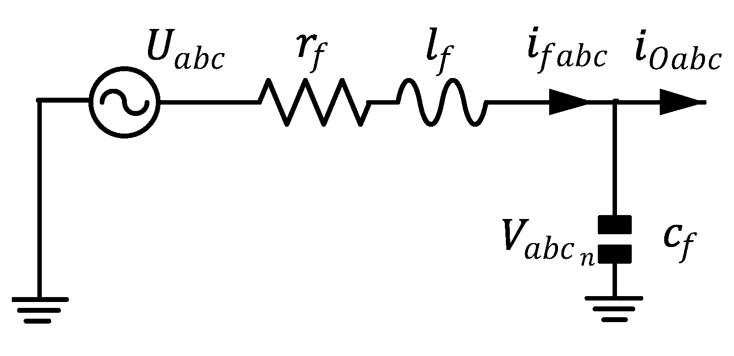
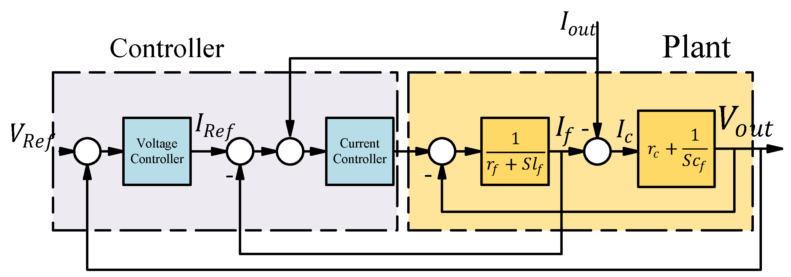
2.2. Controller Structure

Figure 3 shows an equivalent circuit diagram of a three-phase four-wire DG subsystem. The objective is to design a feedback control that robustly regulates the load voltages while the load current is unknown.
We first show that this system can be treated as three decoupled single-input-single-output (SISO) systems, rather than a multi-input-multi-output (MIMO) system. Hamzeh et al. [17] derive a dynamic model for a three-phase three-wired network in the stationary reference frame ( α β ). Since their network has no line-to-neutral currents, they are able to neglect zero-sequence currents. In this work, we use a similar model, but, because this microgrid is a four-wire system, we use three separate state-space parameters to control the microgrid voltage and frequency, resulting in an α β 0 system. After a Clarke transformation, the state-space equation for this system is given by [17,36]
X ˙ = AX + BU + EW , Y = CX ,
where X = v α , v β , v 0 , i f α , i f β , i f 0 T , U = U α , U β , U 0 T , W = i o α , i o β , i o 0 T , Y = v α , v β , v 0 T , and
A = 0 0 0 1 c f 0 0 0 0 0 0 1 c f 0 0 0 0 0 0 1 c f 1 l f 0 0 r f l f 0 0 0 1 l f 0 0 r f l f 0 0 0 1 l f 0 0 r f l f , B = [ 0 0 0 0 0 0 0 0 0 1 l f 0 0 0 1 l f 0 0 0 1 l f ] , E = [ 1 c f 0 0 0 1 c f 0 0 0 1 c f 0 0 0 0 0 0 0 0 0 ] , and C = [ 1 0 0 0 0 1 0 0 ] .
Applying Laplace transform on Equation (1) yields:
s X = A X + B U + E W .
Keeping the state variables of Equation (3) on one side gives:
( s I A ) X = B U + E W ,
so
X = ( s I A ) 1 ( B U + E W ) .
Applying C on X results in Equation (5):
Y ( s ) = G ( 3 × 3 ) ( s ) U ( s ) Z ( 3 × 3 ) ( s ) W ( s ) ,
where
G ( 3 × 3 ) ( s ) = 1 l f c f s 2 + r f c f s + 1 1 0 0 0 1 0 0 0 1 and G ( 3 × 3 ) ( s ) = l f s + r f l f c f s 2 + r f c f s + 1 1 0 0 0 1 0 0 0 1 .
Equation (6) shows that the matrix transfer function of each DG control system is diagonal (completely decoupled) and can be regarded as three SISO control systems. Therefore, the problem of designing a three-input, three-output control system is reduced to designing three one-input, one-output systems.

2.3. Operation Principles of the Proposed Control Strategy

The single line diagram of the LV microgrid that is studied in this paper is shown in Figure 1. The RMS of the phase-to-ground output voltage of DGs in this network is 220 V. All DG units are interfaced to the microgrid through DC/AC converters. The DC-side of each inverter is equipped with multiple sources that consist of a dispatchable unit, such as micro-turbine, a non-dispatchable unit such as the photovoltaic cell, and a surge unit that supplies the system in severe transient conditions. Therefore, these three units provide almost a constant DC voltage for the inverter [37]. Therefore, the energy source of each DG unit is modeled by an ideal DC voltage source, and the dynamics of the DC part of the inverter is not considered in this study. The idea of the control system is to provide the reference voltage for any current that needs to be controlled. The droop controller produces the positive sequence voltage reference, which controls positive sequence current (current is controlled, then active and reactive power are controlled). The VZSIC and VNSIC produce the negative- and zero sequence voltage reference, which control the negative- and zero-sequence current. The control system has four main sections: 1—Voltage control unit: this section follows the voltage reference signal and provides the right current for the loads. Its input is the voltage reference that is generated by the other units (power sharing, VZSIC, and VNDIC). The output of this unit goes to the inverter unit as a reference signal. 2—Average power-sharing: this unit defines how much active and reactive power each unit should provide. It takes the amount of active and reactive power the unit is providing in real time. These inputs then go to the droop control. The outputs of droop control are frequency and voltage reference, which go to the voltage control as discussed in the Unit 1 section. Whenever a change in load consumption happens, the droop changes the frequency and voltage reference in response to these changes. 3 and 4: VZSIC and VNSIC: these two sections produce the negative- and zero-sequence voltage reference based on how much negative- and zero-sequence current each unit should provide, the VZSIC and VNSIC will produce a negative- and zero-sequence voltage reference that causes the DG unit to produce the desired amount of negative- and zero-sequence current. This is how negative and zero-sequence currents are controlled for each unit. The strategy for deciding how much negative- and zero sequence current each unit should provide (reference for VZSIC VNSIC) is detailed in Section 2.5.2.
Controllers are designed in the stationary reference frame ( α β 0 ) which is presented in [17]. It is noted that designing controllers is easier in the synchronous reference frame ( d q 0 ) than the stationary reference frame ( α β 0 ). However, it should be noted that these controllers cannot effectively control a microgrid with unbalanced loads. The proposed control strategy of each unit consists of (1) current controller; (2) voltage controller; (3) average power sharing controller, and (4) negative- and zero-sequence currents’ controller. The current and voltage controllers are proportional resonance (PR) controllers. In an islanded microgrid, it is not necessary to use a PR controller as the current controller since using a simple proportional controller would suffice. However, by using a PR controller as current controller, the proposed control strategy can be used both in islanded mode and grid-connected mode. Therefore, using this controller as the current controller can reduce the cost of design and operation of DG units, while the microgrid can smoothly switch between islanded and grid-connected modes.
Under an unbalanced load condition, the instantaneous power has a double-frequency oscillatory term in addition to the DC power [38]. The conventional droop controller, which is widely adopted to share an average power component, is not able to share the oscillatory power component among the DG units. In [18,39], a virtual negative-sequence impedance controller (VNSIC) was proposed to share the negative-sequence current. However, this approach has not been adopted for zero-sequence current sharing. In this paper, the same approach is adopted to share the zero-sequence current. By controlling the flow of negative- and zero-sequence currents of each DG unit, an oscillatory part of the power of each unit is shared according to its capacity. The strategy for the compensation of zero- and negative-sequence currents is based on the compensating unbalanced loads by its upstream DG unit. Moreover, for loads with no upstream DG unit, the negative- and zero-sequence currents are shared by adjacent DG units. By deploying this strategy, the flow of negative- and zero-sequence currents in microgrid is minimized, and DG units compensate for these currents according to their capacity. Hence, the overall power quality of the the microgrid is improved.

2.4. Proportional Resonance Controller

Because the matrix transfer function of the DG subsystem in equation (6) is diagonal, the three identical SISO controllers can be independently designed for the quadrature axes α , β and 0. Figure 4 shows the structure of the voltage and current controllers for the α , β and 0 axes. A good controller should be able to track the reference signal with a minimum transient and error while it should guarantee a low THD of voltage in the presence of harmonic loads. Since the controllers are designed in the stationary framework, reference signals are sinusoidal. Therefore, the multi-proportional-resonant controller (MPRC) is used. MPRC can track sinusoidal references with zero tracking error, while a conventional PI controller has magnitude and phase error and can not effectively track sinusoidal signals. Therefore, MPRC can handle harmonic loads without deteriorating voltage quality. By using MPRC as the current controller, the control structure can be used in the grid-connected mode of operation as well. Therefore, there is no need for a different control structure in grid-connected mode. As a result, the total cost for design and operation of microgrid decreases. Matlab SISO Tool software (version 2018a, MathWorks, Natick, Massachusetts, U.S.A) is used to design the controllers. It is a graphical tool used to design robust controllers. This tool gets the system plant of the controller, the structure of the controller and the topology of the system. i.e., open loop or closed loop. Through the graphical user interface, the user can design a controller has the desired parameters such as phase margin, gain margin, the locus of poles, damping ratio, and bandwidth. Since the input signal of the control system is sinusoidal, MPRC was selected as a control structure. Considering it multi-resonant, with high gain at desired frequencies, it can track the input signal and damp higher frequencies up to 13th harmonic. However, for this work, only the controller with 50 Hz resonant frequency (with a value of K I 1 ) is important. The rest of the resonant controllers ( K I 2 to K I 13 ) are used to control the harmonics for future works.
The proposed control structure treats the output current as a disturbance. i.e., regardless of the value of output current, the output should follow the reference signal. This structure allows to have control of various types of microgrid topology since the plant of the system does not include loads outside of the DG unit filter.
The transfer function of MPRC is as follows:
C V a n d C I : C ( s ) [ K p + Σ K i h s s 2 + 2 h ω c s + ( h ω 0 ) 2 ] , C ( s ) = g c s + z s + p ,
where C ( s ) is a lead compensator that is added to the structure of the voltage controller to increase the phase margin and bandwidth of the system. Figure 5 shows the Bode diagram of the voltage control loop system. As it is seen from this figure, the system has a good gain margin and a phase margin of 30 degrees while the bandwidth is about 1 kHz. Therefore, the controller shows a robust stability margin and very fast response to load step changes. It also provides and excellent noise and harmonic rejection capability due to its high bandwidth. The coefficients of current and voltage controllers are given in Table 1.

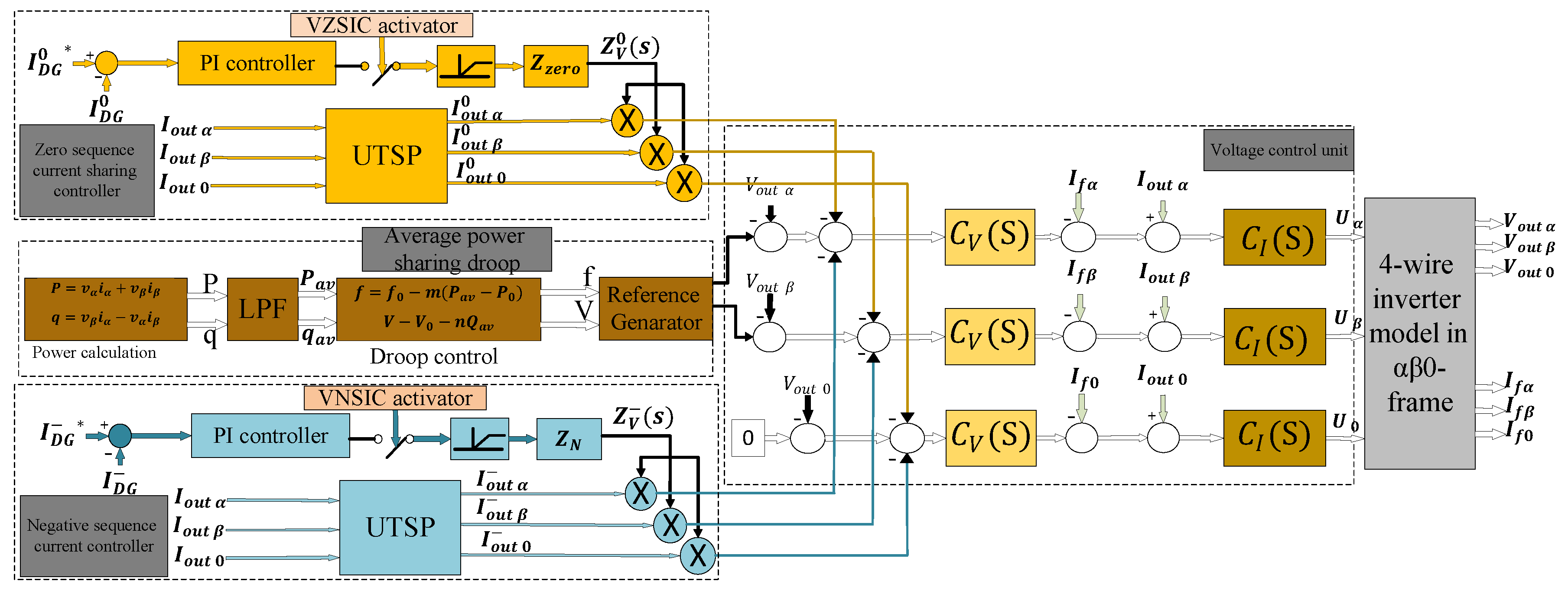
2.5. Proposed Control System

Figure 6 shows the block diagram of the proposed control system. The voltage controller consists of three identical MPRC whose reference signals are determined by the droop control strategy. The droop coefficients, i.e., m, n are obtained according to the rated power of each DG and the maximum deviation of frequency and voltage [40]. The instantaneous real power is calculated using output current and voltage of each DG based on the instantaneous power theory that is proposed in [38]. The instantaneous power is passed through a low pass filter to attenuate the ripples that are caused by unbalanced and harmonic loads. The average power is then applied to the droop controller to determine the working frequency and the voltage magnitude of each DG unit. Then, the voltage and frequency are applied to the reference generator to produce a symmetrical three-phase reference voltage. Since the control structure is in the stationary frame, the Clark transformation is applied to the symmetrical voltage. Therefore, the zero parameters of the Clark transformation will always be zero since the reference voltage is always symmetrical. The output of voltage controller is the reference for the current controller and is compared with the current of the filter inductance. The resultant current is then feed-forwarded to the output current that improves the system stability. The output of the current controller is then applied to the inverter.
To control the zero- and negative-sequence currents, zero- and negative-sequence current controllers are used, respectively. In these blocks, the output current of each DG unit ( I α β 0 ) is decomposed to its symmetrical component with a unified three-phase signal processor (UTSP) [41]. The UTSP block can accurately decompose the symmetrical parameters of current, so that the instantaneous amount of zero- and negative-sequence currents can be obtained from the output current.
The extracted zero- and negative-sequence currents are multiplied by a resistive or inductive impedance gain, Z V and Z V 0 respectively to produce the references for zero- and negative-sequence voltages. These voltages are then added to the reference signals of the voltage controller. The values of Z V and Z V 0 are determined by the virtual negative-sequence impedance controller (VNSIC) and the virtual zero-sequence impedance controller (VZSIC). The virtual impedance blocks compare negative- and zero-sequences of each unit with its negative- or zero-sequence references. The resultant signal is then passed through a PI controller and then multiplied by a resistive or inductive impedance to generate the reference for the virtual impedance of zero- or negative-sequence impedances of each DG unit.

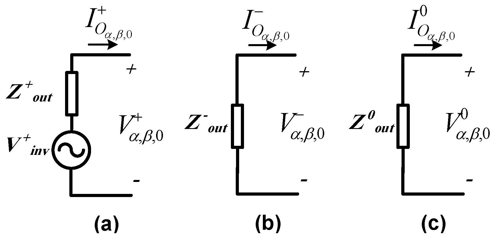
2.5.1. Positive-, Negative- and Zero-Sequence Models of DG Units

To accurately control a DG unit, the dynamic model of Figure 6 can be divided into positive-, negative- and zero-sequence elements. In [39], a dynamic model of the system is divided into positive and negative elements. The same procedure can be adopted to extract the zero-sequence dynamic model. In Figure 6, the voltage of the closed-loop system in the α β 0 -frame can be expressed as:
V α , β , 0 ( s ) = H ( s ) [ V α , β , 0 ( s ) Z V ( s ) I o α , β , 0 ( s ) Z V 0 ( s ) I o α , β , 0 0 ( s ) ] Z o u t ( s ) I o α , β , 0 ( s ) ,
where V α , β , 0 and I o α , β , 0 are the voltage reference signal and the DG terminal current, respectively. H ( s ) denotes the closed-loop transfer function from the reference signal to the output voltage, while Z o u t ( s ) is the output impedance. I o α , β , 0 and I o α , β , 0 0 are the instantaneous negative and zero-sequence components of I o α , β , 0 . Z V ( s ) and Z V 0 ( s ) are the virtual impedances that are determined by the VNSIC and the VZSIC, respectively. The virtual impedance can be inductive or resistive or a combination of both [39]. Equation (8) can be rewritten as:
V α , β 0 + ( s ) + V α , β , 0 ( s ) + V α , β , 0 0 ( s ) = H ( s ) V α , β , 0 ( s ) Z o u t ( s ) I o α , β , 0 + ( s ) [ Z V ( s ) H ( s ) + Z o u t ( s ) ] I o α , β ( s ) [ Z V 0 ( s ) H ( s ) + Z o u t ( s ) ] I o α , β , 0 0 ( s ) .
Equation (9) can be divided into positive-, negative- and zero-sequence voltages. Therefore, the output voltage of DG unit can be expressed as:
V α , β , 0 + ( s ) = H ( s ) V α , β , 0 ( s ) Z o u t ( s ) I o α , β , 0 + ( s ) , V α , β , 0 ( s ) = [ Z V ( s ) H ( s ) + Z o u t ( s ) ] I o α , β , 0 ( s ) , V α , β , 0 0 ( s ) = [ Z V 0 ( s ) H ( s ) + Z o u t ( s ) ] I o α , β , 0 0 ( s ) .
In the working condition of microgrid, H ( j ω 0 ) = 1 0 . In this paper, the virtual impedances Z V and Z V 0 are chosen to be inductive. Therefore, the negative-sequence impedance of each DG unit at the system frequency is:
Z o u t ( j ω 0 ) = Z V ( j ω 0 ) + Z o u t ( j ω 0 ) = R o u t ( ω 0 ) + j [ X o u t ( ω 0 ) + X V ( ω 0 ) ] .
Moreover, the zero-sequence impedance at the system frequency is:
Z o u t 0 ( j ω 0 ) = Z V ( j ω 0 ) + Z o u t ( j ω 0 ) = R o u t ( ω 0 ) + j [ X o u t ( ω 0 ) + X V 0 ( ω 0 ) ] .
To control the negative- and zero-sequence voltages that are injected to the reference of the voltage controller, the X V and X V 0 can be changed. The values of these parameters are set by the VNSIC and the VZSIC of each unit. The negative- and zero-sequence voltages are then injected to the reference of the voltage controller. Therefore, by controlling the negative- and zero-sequence voltages of each unit, the negative- and zero-sequence output currents of each unit are controlled. The maximum permissible values for X V ( ω 0 ) and X V ( ω 0 ) can be calculated based on the IEEE standards [6,42]. Negative- and zero-sequence unbalanced factors are equal to:
( V U F ) = V α , β , 0 V α , β , 0 + = Z o u t I o α , β , 0 V α , β , 0 + < 0 . 02 , ( V U F ) 0 = V α , β , 0 0 V α , β , 0 + = Z o u t 0 I o α , β , 0 0 V α , β , 0 + < 0 . 02 .
Another limiting factor associated with the injection of the negative- and zero-sequence currents is the capability of each unit to inject these currents. Therefore, the capacity of each unit and the inequality constraint in (13) determine the maximum value of the negative- and zero-sequence output impedances. Based on (10), the positive-, negative-, and zero-sequence models for each DG unit are obtained and are shown in Figure 7.

2.5.2. Negative- and Zero-Sequence Currents’ Sharing Strategy

In the previous section, the technical procedure for controlling negative- and zero-sequence currents was explained. In this section, the zero- and negative-sequence current sharing strategy is proposed so that it minimizes the flow of the unbalanced current throughout the LV microgrid. Therefore, the overall power quality of microgrid improves. With the use of an accurate power-sharing strategy, not only the overall power quality of microgrid is improved, but also the proper autonomous operation of the microgrid is guaranteed. In this strategy, the unbalanced current of each load is compensated by its upstream unit. However, the unbalanced currents of loads with no upstream unit are shared by its adjacent units. Considering these two conditions, the reference for negative- and zero-sequence currents of each unit must be as follows:
I D G = I l o c 2 + I n o n l o c 2 + 2 I l o c I n o n l o c cos θ , I D G 0 = I l o c 0 2 + I n o n l o c 0 2 + 2 I l o c 0 I n o n l o c 0 cos θ 0 ,
where I l o c and I l o c 0 are magnitudes of the negative- and zero-sequence currents of the local loads, respectively. θ and θ 0 are the phase difference between I l o c and I n o n l o c for the negative- and zero-sequence currents, respectively.
I n o n l o c and I n o n l o c 0 are defined as:
I n o n l o c = I m a x D G i I m a x D G i I n o n l o c , I n o n l o c 0 = I m a x D G i 0 I m a x D G i 0 I n o n l o c 0 .
In (15), I m a x D G i and I m a x D G i 0 are respectively the maximum negative- and zero-sequence currents that the i t h DG can inject. I n o n l o c and I n o n l o c 0 are the amplitudes of the negative- and zero-sequence of feeders supplying the nonlocal load. Referring to (15) and (14), the local unbalanced loads are compensated locally while the unbalanced loads with no upstream DG unit are shared among all DG units according to their unbalanced load capacity. By using PMU, which is installed on feeders, the phase difference between local and nonlocal currents is calculated. If all impedances of lines are known, the PMU unit can be omitted. Since the impedances of lines are usually unknown, with the help of an PMU unit, an accurate power sharing can be achieved. This method has an advantage over other power sharing methods that only consider amplitude of unbalanced currents as it considers both amplitude and phasor of unbalanced currents. For example, in some scenarios, the unbalanced currents of some loads can nullify those of other loads, while the DG unit remains under balanced condition. Thus, if the phasor of currents is not considered, the reference currents for virtual impedance loop will not be accurate. In the proposed control strategy, the VNSIC and VZSIC are enabled when: (1) The DG unit reaches to its maximum capacity so that it is not able to inject the required negative and zero sequence currents. When the VNSIC and the VZSIC are disabled, the virtual impedances of the unit are kept at the minimum value, i.e., X V = X V 0 =0. This means that the DG unit compensates all unbalanced loads in its downstream. When a DG unit reaches to its maximum capacity, X V and X V 0 are changed to prevent the unit from overloading. (2) The control system of the DG unit detects unbalanced current flow from adjacent feeders. Therefore, the DG units change their virtual impedances accordingly to share the remaining unbalanced currents. Otherwise, the VNSIC and VZSIC are disabled, and the negative- and zero-sequence of the output impedances are kept constant at the minimum value. When VNSIC and VZSIC are activated, the PI controllers set Z V 0 and Z V to a desirable value.

2.6. PSCAD Implementation

Here, we give a brief description of the PSCAD implementation of the controller. The model files are available as supplemental material accompanying this paper.
Each of the DG units in Figure 1 are equipped with the control structure of Figure 4. The sensors at the terminals measure voltage, current, active and reactive power of each DG unit. The active and reactive measured powers are fed into the droop control system. The output of the droop controller is reference voltage and frequency. The produced voltage and frequency go to the Reference generator unit where it transforms it into a symmetrical three-phase voltage. Since all controllers are designed in α β 0 structure, stationary reference frame transformation is applied to this voltage signal too. The result of the reference generator unit is the input to the voltage control unit. The actual output voltage subtracted from the reference signal produced by the signal generator unit then goes into the voltage control unit. The output of the voltage control unit is then subtracted from the output current and is then sent into the current control unit. The resultant output of the current control unit is the reference signal for the inverter in the PSCAD simulation. A controlled voltage source is used as an ideal inverter.
The voltage control unit and average power sharing unit in Figure 4 represent the primary and secondary controller of the microgrid, respectively, where active and reactive power are controlled by the droop controller, and frequency and voltage are controlled by the voltage control unit. The VZSIC and VNSIC controller represent the auxiliary control units, which are responsible for controlling zero- and negative sequence current in the microgrid. The reference current is defined by the strategy stated in the Results section. The reference (DC signal) is compared to the actual current where it is fed into the PI controller. The output current is multiplied to Z z e r o and Z n e g a t i v e , respectively, to produce the reference for zero- and negative-sequence currents, respectively. The idea of the control system is to provide the reference voltage for any current that needs to be controlled. The droop controller produces the positive-sequence voltage reference, which is used to control positive sequence current (current is controlled, and then active and reactive power are controlled). The VZSIC and VNSIC produce the negative- and zero sequence voltage reference, which is used to control negative- and zero-sequence current.

3. Results and Discussion

To verify the effectiveness of the proposed control strategy, the LV microgrid shown in Figure 1 has been simulated in a PSCAD/EMTDC environment. The LV microgrid is assumed to operate in islanded mode and is comprised of a three-feeder distribution system with two electronically-coupled four-wire dispatchable DG units. All DG units are equipped with the PR controller, droop control strategy, VNSIC, and VZSIC. The parameters of the microgrid including all DG units are given in Table 2. Several load changes are introduced to the microgrid aiming to verify its dynamic performance.

3.1. Case Study 1

In this case study, initially, two balanced loads are connected to feeders F 1 and F 3 . The load that is connected to feeder F 3 is a three-phase R L load with the nominal power of 285 kVA and a power factor of P F = 0.88, while the load connected to feeder F 1 is a three-phase R L load with 75 kVA with P F = 0.9. A single-phase load rated 40 kVA with P F = 0.98 is connected to one phase of feeder F 1 at t = 2 s. Subsequent to this load change, at t = 5 s, another single-phase load rated 26 kVA with P F = 0.95 is connected to the same phase of feeder F 1 . Figure 8a shows the frequency of the system. The droop coefficient is set so that, on the no-load situation, the frequency stays at 50 Hz. With the use of conventional droop with a dynamic coefficient, the voltage and frequency reach stable mode after about 0.5 seconds of transient time. Figure 8b shows the voltage output at the DG1 terminal. After addition of unbalanced load to the loads, a double frequency ripple is added to frequency and voltage of the network. The frequency and voltage deviation is less than 1% and 5% for frequency and voltage, respectively, which demonstrate that the deviation is in the range of acceptable limit for frequency and voltage.
The instantaneous real and reactive powers considering these load changes are shown in Figure 9. Since feeder F 1 becomes unbalanced, a double-frequency ripple appears on the instantaneous power components of this feeder. As it is observed, the double-frequency ripple amplitude increases as another unbalanced load is connected to the feeder F 1 at t = 5 s.
Figure 10 shows the positive-, negative- and zero-sequence current components of feeder F 1 that increases at t = 2 s and t = 5 s.
The first step toward controlling power component effectively is controlling Active and reactive powers. If these components are not controlled accurately, it will not be possible to share other power components effectively. Figure 11a,b show the zero-sequence output impedances and the zero-sequence currents of the DGs, respectively. As it was mentioned earlier, the primary aim of the unbalanced current sharing strategy is to compensate zero- and negative-sequence currents locally. However, if the maximum capacity of a unit to compensate unbalanced currents is reached, other units inject the remaining unbalanced current. Prior to t = 5 s, the VZSIC and VNSIC of the DG units are not activated, and virtual impedances are kept at the minimum value.
Figure 11b shows that almost all zero-sequence current of the unbalanced load is compensated by unit 1. However, when another unbalanced load is added to feeder F 1 at t = 5 s, the maximum capacity of the adjacent unit ( D G 1 ) is reached, and the remaining unbalanced current is then provided by the other unit ( D G 2 ). This operation is done by increasing the zero-sequence virtual impedance of unit 1 when the VZSIC of unit 1 detects that the maximum capacity of the unit is reached.
Figure 12a,b show the negative-sequence output impedance and the negative-sequence currents of the DGs, respectively. The same scenario happens for negative-sequence current when the maximum capacity of unit 1 for providing negative-sequence current is reached, and the remaining negative-sequence current is shared by another unit through the activation of VNSIC. Figure 11c and Figure 12c show, respectively, the voltage unbalanced factor ( V U F ) for the zero- and negative-sequence voltage of DG units during load changes. The V U F of D G 1 is always under 2% for zero- and negative-sequences while DG1 is injecting the maximum value of zero- and negative-sequence currents.
Figure 13 shows instantaneous real and reactive power components of DG units. The magnitude of double-frequency ripple on the output power of each unit is proportional to its unbalanced current share. Before the t = 2 s, all loads in the system are balanced. The rating power of both DGs is the same. Therefore, their share of active and reactive power is the same. Figure 13a shows the active power output of DG units. As it seems, both units provide the exact amount of active power. Figure 13b shows the reactive power output of DG units. The reactive power sharing in LV networks is not as accurate as an active power component. Since the ratio of reactance to inductance in an LV network is high, usually active and reactive power components are not decoupled effectively. However, the accuracy of reactive power sharing is quite acceptable for this research for which its goal is demonstrating unbalanced current sharing in LV networks.

3.2. Case Study 2

In this case study, the microgrid begins to operate with two balanced loads. The first load is a three-phase 75 kVA with P F = 0.9, which is connected to the feeder F 1 and the second is a 285 kVA with P F = 0.88, which is connected to feeder F 3 . Two single-phase loads rated 20 kVA with P F = 0.98 are connected to the phase b and c of feeder F 3 at t = 2 s. Subsequently, two single-phase loads are connected to the phase b and c of feeder F 1 at t = 5 s and are disconnected at t = 8 s. Then, a single-phase load rated 8 kVA and P F = 0.96 is connected to the phase a of feeder F 1 at t = 11 s. Figure 14 shows the voltage and frequency. through out the test, the voltage and frequency are within the predefined limit which shows the proper design of droop coefficients. Also, the settling time is very short which shows the robustness of the voltage and current controller design. Figure 15 shows the instantaneous real and reactive power components of feeders. When the unbalanced loads are connected to the phase b and c of feeder F 3 , a 100 Hz ripple appears on the power components of feeder F 3 . Furthermore, this ripple appears on the power components of feeder F 1 when unbalanced loads are connected to it.
Figure 16 shows the positive-, negative- and zero-sequence current components of the feeders. In this case study, loads that are fed from feeder F 3 have no upstream DG unit. Therefore, unbalanced loads connected to this feeder should be shared by their adjacent units.
Figure 17a and Figure 18a show the zero- and negative-sequence virtual impedances of DG units. After the connection of the unbalanced loads to feeder F 3 at t = 2 s, the VZSIC and VNSIC are activated at t = 2.4 s. While VZSIC and VNSIC are not activated, the unbalanced load sharing is performed according to the line impedances. Figure 17b and Figure 18b show the zero- and the negative-sequence current components of the DG units, respectively. Having activated the VZSIC and VNSIC of D G 1 , the unbalanced current of feeder F 3 is shared between DG units according to their negative- and zero-sequence capacities that are considered to be equal for units. Therefore, negative- and the zero-sequence current components of units becomes equal. When the unbalanced load is connected to feeder F 1 at t = 5 s, it should be compensated by unit 1 according to the proposed strategy. Therefore, D G 1 decreases its Z V and Z V 0 . As it can be seen from Figure 17b and Figure 18b, the unbalanced load current flowing through feeder F 1 at t = 5 s is completely compensated by D G 1 while the portion of unbalanced current injected by D G 2 is kept intact. At t = 8 s, the unbalanced load is disconnected from feeder F 1 . Therefore, VZSIC and VNSIC units of D G 1 increase Z V and Z V 0 so that the unbalanced current portion of units become equal. At t = 11 s, a single-phase load is connected to the phase a of feeder F 1 . However, this load compensates a portion of the unbalanced load connected to the phase b and c of feeder F 3 . Therefore, the portion of the unbalanced current supplied by D G 1 is decreased. The VZSIC and VNSIC increase the virtual impedances to accommodate this situation. If the amplitude of unbalanced current had only been considered ignoring its phase, the calculation of I D G and I D G 0 would have been incorrect causing inaccurate current sharing. Figure 17c and Figure 18c show the voltage unbalanced factor for zero- and negative-sequence voltages. Throughout the simulation time, V U F has a good condition and is always kept under 2%.
Figure 19 shows the output powers of DG units. The double-frequency ripple on the output powers stems from the unbalanced power. When the unbalanced load is connected to the feeder F 3 , the 100 Hz frequency ripple appears in the output power. After t = 5 s, the portion of the unbalanced power for D G 1 increases while the portion of D G 2 does not change. The unbalanced quota of units become equal after t = 8 s. It shows that the control strategy has managed to share the unbalanced power in the microgrid with excellent accuracy.

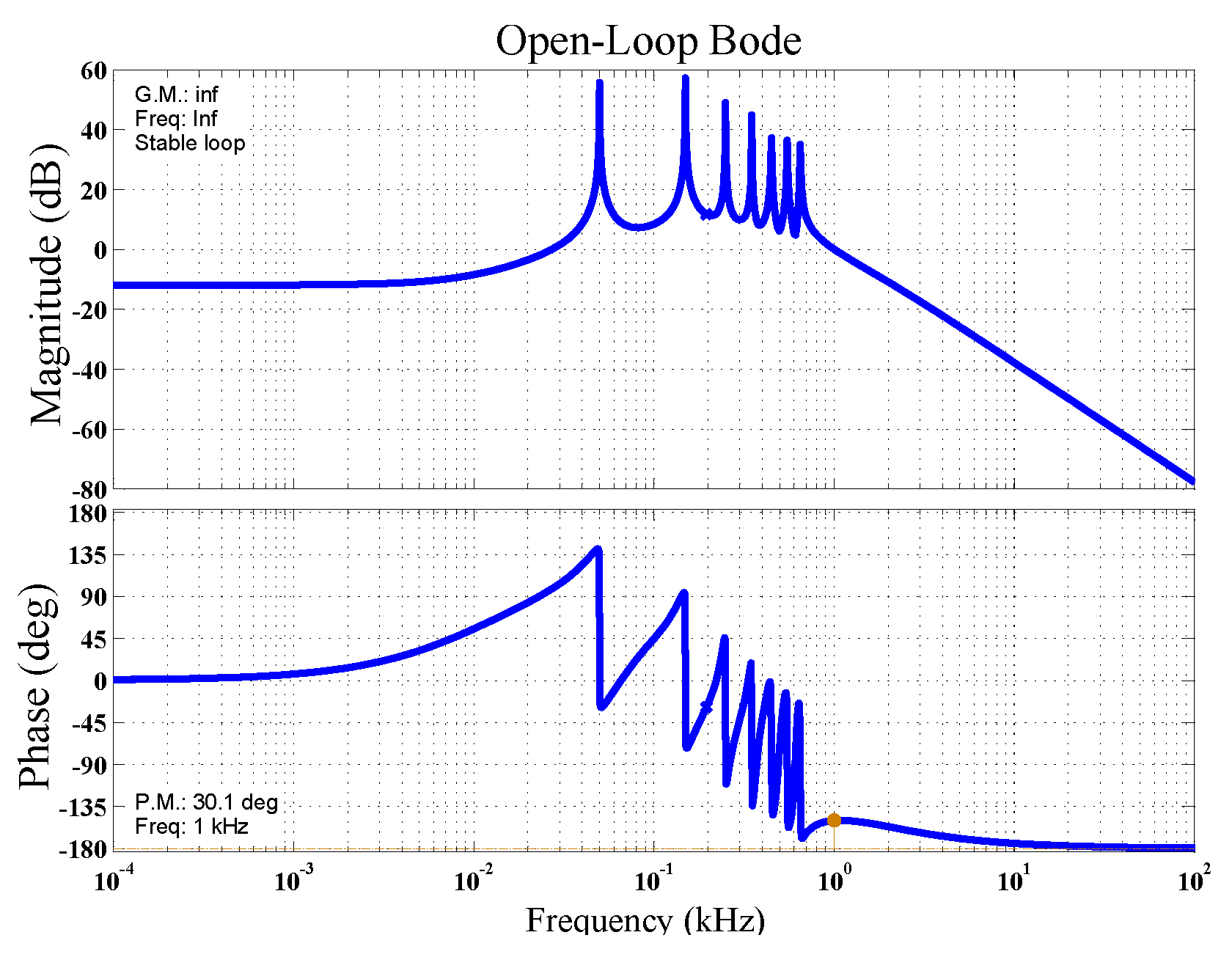
3.3. Sensitivity and Stability Studies

The supplementary material accompanying this paper includes a large collection of sensitivity and stability studies. These test the controller with a variety of network configurations and faults, without any adjustment to the controller parameters, in order to illustrate its ability to adapt automatically to different microgrids and conditions.

4. Conclusions

A comprehensive strategy was presented for sharing unbalanced current in an islanded LV microgrid consisting of dispatchable units. In the proposed method, the zero- and negative-sequence currents are shared based on a novel strategy that decreases the flow of unbalanced current in the microgrid improving the overall power quality. In the proposed strategy, the zero- and negative-sequence currents of nonlocal loads are completely compensated by their associated DG units. However, if the capacity of a unit is not enough to offset the zero- and/or negative-sequence current terms or the unbalanced load has no upstream unit, the unbalanced current is shared among adjacent units. The proposed control strategy comprises a PR controller, a droop controller, a virtual negative-sequence impedance controller (VNSIC) and a virtual zero-sequence impedance controller (VZSIC). With VNSIC and VZSIC, the DG units can effectively share the negative- and zero-sequence currents. The performance of the proposed control strategy was evaluated by using digital time-domain simulation studies in PSCAD/EMTDC software. From the simulation results, we found that the proposed control strategy can
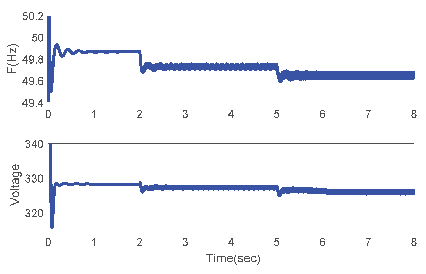
  • control voltage and frequency while maintaining them within their allowable limits,
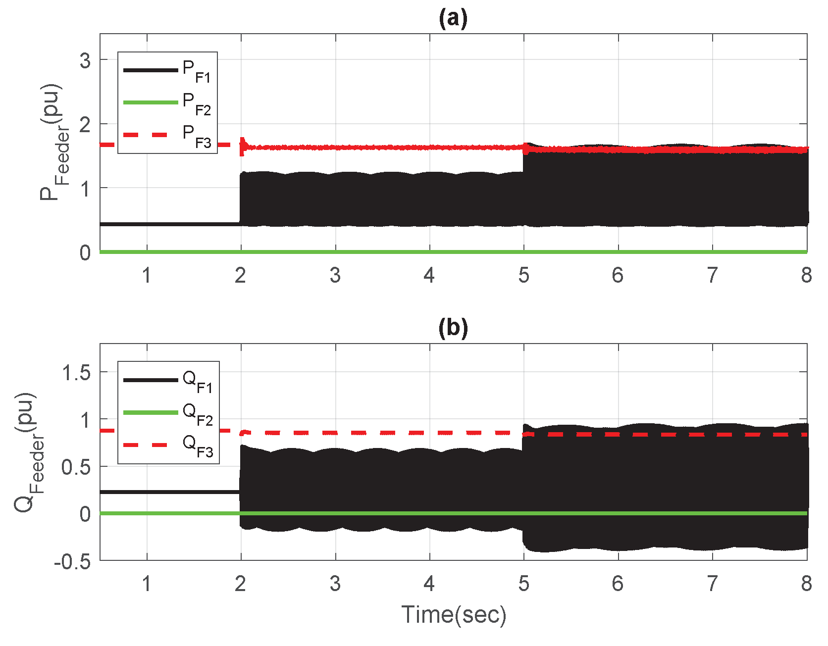
  • share the average power among DG units, and
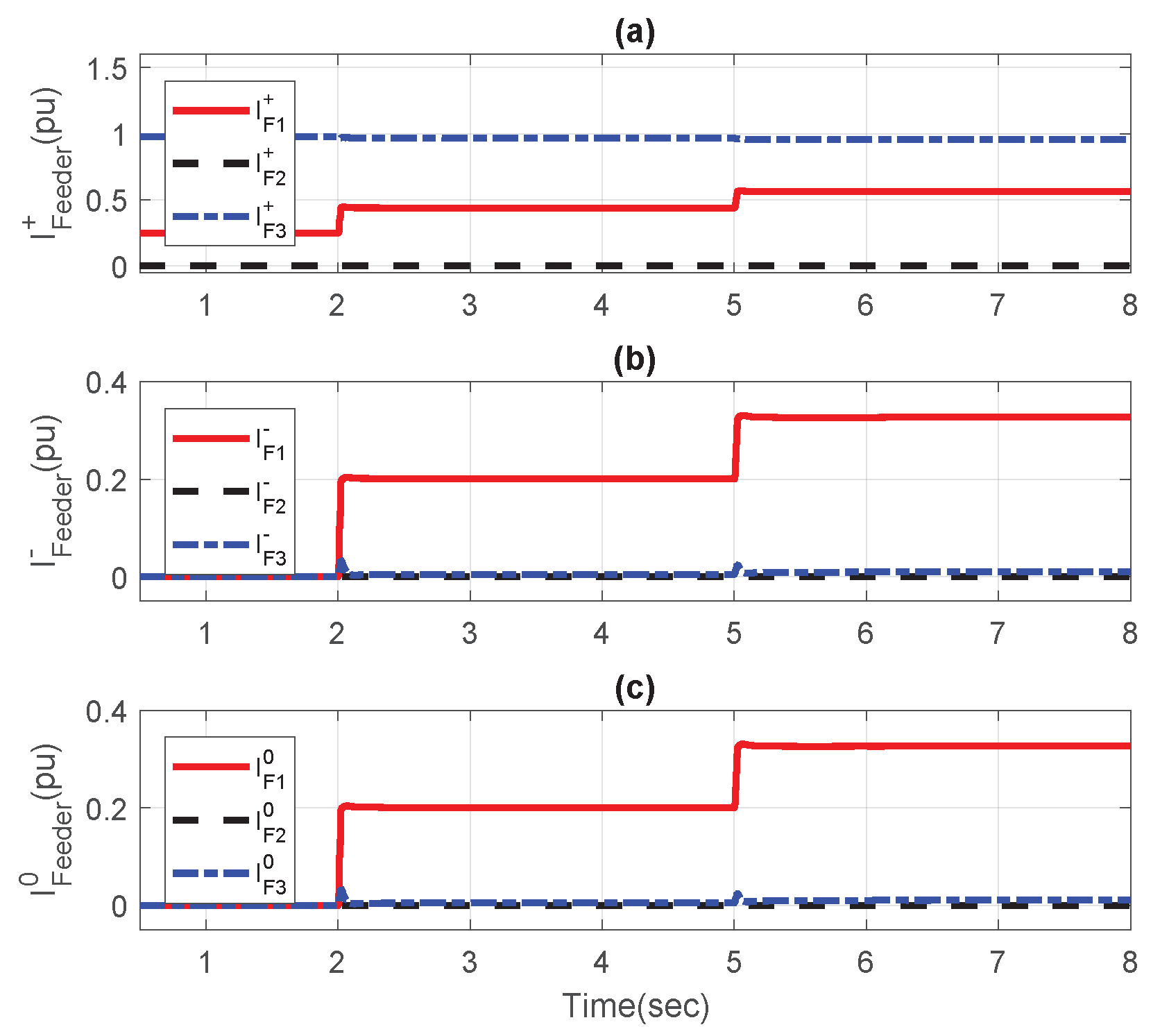
  • effectively compensate the zero- and negative-sequence currents of unbalanced loads in a four-wired LV microgrid so that the power quality of the overall microgrid is improved.

Supplementary Materials

Supplementary File 1

Author Contributions

Conceptualization, F.N., M.H. and M.F.; Methodology, F.N., M.H. and M.F.; Software, F.N.; Validation, F.N.; Formal Analysis, F.N.; Investigation, F.N.; Resources, M.F.; Data Curation, F.N.; Writing—Original Draft Preparation, F.N. and M.F.; Writing—Review and Editing, F.N. and M.F.; Visualization, F.N.; Supervision, M.F.; Project Administration, M.F.; Funding Acquisition, M.F.

Funding

This research was partly funded by grants from the Ulupono Initiative and Blue Planet Foundation.

Conflicts of Interest

The authors declare no conflict of interest. The funding sponsors had no role in the design of the study; in the collection, analyses, or interpretation of data; in the writing of the manuscript, and in the decision to publish the results.

Abbreviations

The following abbreviations are used in this manuscript:
MDPIMultidisciplinary Digital Publishing Institute
DOAJDirectory of Open Access Journals
TLAThree Letter Acronym
LDLinear Dichroism
VSIVoltage Source Inverter
APFActive Power Filter
VUFVoltage Unbalanced Factor
kVAkilo Volt Ampere
DCDirect Current
ACAlternating Current
MGMicro Grid
DGDistributed Generator
RMSRoot Mean Square
VZSICVirtual Zero Sequence Impedance Controller
VNSICVirtual Negative Sequence Impedance Controller
DERDistributed Energy Resources
LVLow Voltage
PRProportional-Resonant
THDTotal Harmonic Distortion
MPRCMulti-Proportional-Resonant Controller
UTSPUnified Three-Phase Signal Processor
PMUPhase Measurement Unit
PSCADPower System Computer Aided Design
EMTDCElectro Magnetic Transient Design and Control

References

  1. Li, B.; Roche, R.; Miraoui, A. Microgrid sizing with combined evolutionary algorithm and MILP unit commitment. Appl. Energy 2017, 188, 547–562. [Google Scholar] [CrossRef]
  2. Shahnia, F.; Chandrasena, R.P.S. A three-phase community microgrid comprised of single-phase energy resources with an uneven scattering amongst phases. Int. J. Electr. Power Energy Syst. 2017, 84, 267–283. [Google Scholar] [CrossRef]
  3. Palizban, O.; Kauhaniemi, K.; Guerrero, J.M. Microgrids in active network management—Part I: Hierarchical control, energy storage, virtual power plants, and market participation. Renew. Sustain. Energy Rev. 2014, 36, 428–439. [Google Scholar] [CrossRef] [Green Version]
  4. Hochgraf, C.; Lasseter, R.H. Statcom controls for operation with unbalanced voltages. IEEE Trans. Power Deliv. 1998, 13, 538–544. [Google Scholar] [CrossRef] [Green Version]
  5. Pati, J.C.; Sahu, J.K. Unbalanced Load Compensation. Int. J. Adv. Res. Sci. Technol. 2012, 1, 74–80. [Google Scholar]
  6. Smith, J.C.; Hensley, G.; Ray, L. IEEE Recommended Practice for Monitoring Electric Power Quality. IEEE Std. 1995, 1159–1995. [Google Scholar]
  7. Shahnia, F.; Majumder, R.; Ghosh, A.; Ledwich, G.; Zare, F. Operation and control of a hybrid microgrid containing unbalanced and nonlinear loads. Electr. Power Syst. Res. 2010, 80, 954–965. [Google Scholar] [CrossRef] [Green Version]
  8. Salmerón Revuelta, P.; Pérez Litrán, S.; Prieto Thomas, J.; Salmerón Revuelta, P.; Pérez Litrán, S.; Prieto Thomas, J. 4 – Shunt Active Power Filters. In Active Power Line Conditioners; Academic Press: Cambridge, MA, USA, 2016; pp. 107–147. [Google Scholar]
  9. Shah, S.; Sensarma, P.S. Three Degree of Freedom Robust Voltage Controller for Instantaneous Current Sharing Among Voltage Source Inverters in Parallel. IEEE Trans. Power Electron. 2010, 25, 3003–3014. [Google Scholar] [CrossRef]
  10. Low, K.S.; Cao, R. Model Predictive Control of Parallel-Connected Inverters for Uninterruptible Power Supplies. IEEE Trans. Ind. Electron. 2008, 55, 2884–2893. [Google Scholar] [CrossRef]
  11. De, D.; Ramanarayanan, V. Decentralized Parallel Operation of Inverters Sharing Unbalanced and Nonlinear Loads. IEEE Trans. Ind. Electron. 2010, 25, 3015–3025. [Google Scholar] [CrossRef]
  12. Rezaei, M.M.; Soltani, J. A robust control strategy for a grid-connected multi-bus microgrid under unbalanced load conditions. Int. J. Electr. Power Energy Syst. 2015, 71, 68–76. [Google Scholar] [CrossRef]
  13. Jin, P.; Li, Y.; Li, G.; Chen, Z.; Zhai, X. Optimized hierarchical power oscillations control for distributed generation under unbalanced conditions. Appl. Energy 2016. [Google Scholar] [CrossRef]
  14. Carpinelli, G.; Mottola, F.; Proto, D.; Varilone, P. Minimizing unbalances in low-voltage microgrids: Optimal scheduling of distributed resources. Appl. Energy 2017, 191, 170–182. [Google Scholar] [CrossRef]
  15. Cheng, P.T.; Chen, C.A.; Lee, T.L.; Kuo, S.Y. A Cooperative Imbalance Compensation Method for Distributed-Generation Interface Converters. IEEE Trans. Ind. Appl. 2009, 45, 805–815. [Google Scholar] [CrossRef]
  16. Kim, J.; Guerrero, J.M.; Rodriguez, P.; Teodorescu, R.; Nam, K. Mode Adaptive Droop Control With Virtual Output Impedances for an Inverter-Based Flexible AC Microgrid. IEEE Trans. Power Electron. 2011, 26, 689–701. [Google Scholar] [CrossRef]
  17. Hamzeh, M.; Karimi, H.; Mokhtari, H. A New Control Strategy for a Multi-Bus MV Microgrid Under Unbalanced Conditions. IEEE Trans. Power Syst. 2012, 27, 2225–2232. [Google Scholar] [CrossRef]
  18. Hamzeh, M.; Karimi, H.; Mokhtari, H. Harmonic and Negative-Sequence Current Control in an Islanded Multi-Bus MV Microgrid. IEEE Trans. Smart Grid 2014, 5, 167–176. [Google Scholar] [CrossRef]
  19. Rowe, C.N.; Summers, T.J.; Betz, R.E.; Cornforth, D.J.; Moore, T.G. Arctan Power–Frequency Droop for Improved Microgrid Stability. IEEE Trans. Power Electron. 2013, 28, 3747–3759. [Google Scholar] [CrossRef]
  20. Mehrasa, M.; Pouresmaeil, E.; Jørgensen, B.N.; Catalão, J.P.S. A control plan for the stable operation of microgrids during grid-connected and islanded modes. Electr. Power Syst. Res. 2015, 129, 10–22. [Google Scholar] [CrossRef] [Green Version]
  21. Savaghebi, M.; Jalilian, A.; Vasquez, J.C.; Guerrero, J.M. Secondary Control for Voltage Quality Enhancement in Microgrids. IEEE Trans. Smart Grid 2012, 3, 1893–1902. [Google Scholar] [CrossRef] [Green Version]
  22. Delghavi, M.B.; Yazdani, A. Islanded-mode control of electronically coupled distributed-resource units under unbalanced and nonlinear load conditions. IEEE Trans. Power Deliv. 2011, 26, 661–673. [Google Scholar] [CrossRef]
  23. Quan, X.; Dou, X.; Wu, Z.; Hu, M.; Yuan, J. Harmonic voltage resonant compensation control of a three-phase inverter for battery energy storage systems applied in isolated microgrid. Electr. Power Syst. Res. 2016, 131, 205–217. [Google Scholar] [CrossRef]
  24. Saim, A.; Mellah, R.; Houari, A.; Machmoum, M.; Djerioui, A. Adaptive resonant based multi-loop control strategy for parallel distributed generation units in standalone microgrid application. Electr. Power Syst. Res. 2017, 143, 262–271. [Google Scholar] [CrossRef]
  25. Abdelaziz, M.M.A.; El-Saadany, E.F. Economic droop parameter selection for autonomous microgrids including wind turbines. Renew. Energy 2015, 82, 108–113. [Google Scholar] [CrossRef]
  26. Dasgupta, S.; Mohan, S.N.; Sahoo, S.K.; Panda, S.K. A plug and play operational approach for implementation of an autonomous-micro-grid system. IEEE Trans. Ind. Inform. 2012, 8, 615–629. [Google Scholar] [CrossRef]
  27. Sao, C.; Lehn, P. Autonomous Load Sharing of Voltage Source Converters. IEEE Trans. Power Deliv. 2005, 20, 1009–1016. [Google Scholar] [CrossRef]
  28. Mohamed, Y.; El-Saadany, E. Adaptive Decentralized Droop Controller to Preserve Power Sharing Stability of Paralleled Inverters in Distributed Generation Microgrids. IEEE Trans. Power Electron. 2008, 23, 2806–2816. [Google Scholar] [CrossRef]
  29. Tuladhar, A.; Jin, H.; Unger, T.; Mauch, K. Parallel operation of single phase inverter modules with no control interconnections. In Proceedings of the Twelfth Annual Applied Power Electronics Conference and Exposition (APEC’ 1997), Atlanta, GA, USA, 23–27 February 1997; Volume 1, pp. 94–100. [Google Scholar]
  30. Guerrero, J.M.; Hang, L.; Uceda, J. Control of distributed uninterruptible power supply systems. IEEE Trans. Ind. Electron. 2008, 55, 2845–2859. [Google Scholar] [CrossRef] [Green Version]
  31. Blaabjerg, F.; Teodorescu, R.; Liserre, M.; Timbus, A. Overview of Control and Grid Synchronization for Distributed Power Generation Systems. IEEE Trans. Ind. Electron. 2006, 53, 1398–1409. [Google Scholar] [CrossRef] [Green Version]
  32. Guerrero, J.; GarciadeVicuna, L.; Matas, J.; Castilla, M.; Miret, J. Output Impedance Design of Parallel-Connected UPS Inverters With Wireless Load-Sharing Control. IEEE Trans. Ind. Electron. 2005, 52, 1126–1135. [Google Scholar] [CrossRef]
  33. Zhang, Y.; Yu, M.; Liu, F.; Kang, Y. Instantaneous Current Sharing Control Strategy for Parallel Operation of UPS Modules Using Virtual Impedance. IEEE Trans. Power Electron. 2011, 28, 432–440. [Google Scholar] [CrossRef]
  34. Harnefors, L.; Bongiorno, M.; Lundberg, S. Input-Admittance Calculation and Shaping for Controlled Voltage-Source Converters. IEEE Trans. Ind. Electron. 2007, 54, 3323–3334. [Google Scholar] [CrossRef]
  35. Li, Y.W.; Kao, C.-N. An Accurate Power Control Strategy for Power-Electronics-Interfaced Distributed Generation Units Operating in a Low-Voltage Multibus Microgrid. IEEE Trans. Power Electron. 2009, 24, 2977–2988. [Google Scholar] [CrossRef]
  36. Marwali, M.N.; Keyhani, A. Control of distributed generation systems-part I: voltages and currents control. IEEE Trans. Power Electron. 2004, 19, 1541–1550. [Google Scholar] [CrossRef]
  37. Ghazanfari, A.; Hamzeh, M.; Mokhtari, H.; Karimi, H. Active power management of multi-hybrid fuel cell/supercapacitor power conversion system in a medium voltage microgrid. IEEE Trans. Smart Grid 2012, 3, 1903–1910. [Google Scholar] [CrossRef]
  38. Akagi, H.; Watanabe, E.H.; Aredes, M. Instantaneous Power Theory and Applications to Power Conditioning; Wiley: hoboken, NJ, USA, 2007. [Google Scholar]
  39. Hamzeh, M.; Karimi, H.; Mokhtari, H.; Mahseredjian, J. Control of a microgrid with unbalanced loads using virtual negative-sequence impedance loop. In Proceedings of the 5th Annual International Power Electronics, Drive Systems and Technologies Conference (PEDSTC 2014), Tehran, Iran, 5–6 February 2014; pp. 78–83. [Google Scholar] [CrossRef]
  40. Chandorkar, M.; Divan, D.; Adapa, R. Control of parallel connected inverters in standalone AC supply systems. IEEE Trans. Ind. Appl. 1993, 29, 136–143. [Google Scholar] [CrossRef] [Green Version]
  41. Karimi, H.; Yazdani, A.; Iravani, R. Negative-Sequence current injection for fast islanding detection of a distributed resource unit. IEEE Trans. Power Electron. 2008, 23, 298–307. [Google Scholar] [CrossRef]
  42. Cooper, C. IEEE recommended practice for electric power distribution for industrial plants. Electron. Power 1987, 33, 658. [Google Scholar] [CrossRef]
Figure 1. LV multi-bus MG consisting of two DG units.
Energies 11 02776 g001
Figure 2. Three-phase four-wired inverter.
Energies 11 02776 g002
Figure 3. Single phase diagram of an inverter.
Energies 11 02776 g003
Figure 4. Plant for voltage and current controller.
Energies 11 02776 g004
Figure 5. Bode diagram.
Energies 11 02776 g005
Figure 6. Control structure of DG units.
Energies 11 02776 g006
Figure 7. (a) positive-; (b) negative- and (c) zero-sequence models of the DG unit.
Energies 11 02776 g007
Figure 8. Instantaneous voltages at the DG terminals during unbalanced load changes in feeder F 1 , (a) D G 1 and (b) D G 2 .
Energies 11 02776 g008
Figure 9. Unbalanced load changes in feeder F 1 (a) instantaneous real and (b) reactive power of feeders.
Energies 11 02776 g009
Figure 10. (a) Positive-, (b) negative- and (c) zero-sequence currents of the feeders.
Energies 11 02776 g010
Figure 11. Zero-sequence (a) output impedance, (b) current, and (c) VUF of DG units.
Energies 11 02776 g011
Figure 12. Negative-sequence (a) output impedance, (b) current, and (c) VUF of DG units.
Energies 11 02776 g012
Figure 13. Dynamic response of DG units to unbalanced load changes in feeder F 1 : (a) real power, and (b) reactive power components of DG units.
Energies 11 02776 g013
Figure 14. Instantaneous voltages at the DG terminals during unbalanced load changes in feeder F 1 , (a) D G 1 and (b) D G 2 .
Energies 11 02776 g014
Figure 15. Unbalanced load changes in feeders F 3 and F 2 (a) instantaneous real and (b) reactive power of feeders.
Energies 11 02776 g015
Figure 16. (a) positive and (b) negative, and (c) zero-sequence currents of the feeders.
Energies 11 02776 g016
Figure 17. Zero-sequence (a) output impedance, (b) current, and (c) VUF of DG units.
Energies 11 02776 g017
Figure 18. Negative-sequence (a) output impedance, (b) current, and (c) VUF of DG units.
Energies 11 02776 g018
Figure 19. Dynamic response of DG units to unbalanced load changes in feeder F 1 and F 3 : (a) real power, and (b) reactive power components of DG units.
Energies 11 02776 g019
Table 1. Controller’s parameters.
Parameter C I C V
C ( s ) - g c = 3.7 , z = 60 , p = 8 × 10 3
K p 117.71
K I 1 600 5 × 10 3
K I 3 1 × 10 3 7 × 10 3
K I 5 1.2 × 10 3 4.5 × 10 3
K I 7 1.6 × 10 3 5 × 10 3
K I 9 2.6 × 10 3 10 × 10 3
K I 11 2.8 × 10 3 14 × 10 3
K I 13 - 17 × 10 3
ω 0 2 × 50 × π 2 × 50 × π
ω c π π
Table 2. MG system parameters.
ParameterValueComments
S b a s e 300 kVADG ratings
Z l i n e 1 0.04 + j 0.0157 p . u . 0.8 km overhead line
Z l i n e 2 0.07 + j 0.0332 p . u . 1.3 km overhead line
Z l i n e 3 0.01 + j 0.0022 p . u . 0.2 km overhead line
L f 1 , L f 2 0.3 mHseries filter inductance
r f 1 , r f 2 0.0015 Ωseries filter resistance
C f 1 , C f 2 2200 μ Ffilter capacitance
V D C 1500 VDC bus voltage
f s 6 kHzswitching frequency
P D G 1 , 2 , P D G 2 100 KWmaximum real power
Q D G 1 , Q D G 2 100 kVArmaximum reactive power
m D G 1 , m D G 2 3.33 Hz/MWP-f droop coefficients
n D G 1 , n D G 2 3.26V/MVArQ-V droop coefficients
I m a x D G 1 , I m a x D G 2 97 A (0.13 p.u.)
I m a x D G 1 0 , I m a x D G 2 0 97 A (0.13 p.u.)
k P n 1 , k I n 1 3 × 10 6 , 1 × 10 3 VNSIC parameters of D G 1
k P n 2 , k I n 2 3 × 10 6 , 1 × 10 3 VNSIC parameters of D G 2
k P z 1 , k I z 1 1 × 10 6 , 2 × 10 3 VZSIC parameters of D G 1
k P z 2 , k I z 2 1 × 10 6 , 2 × 10 3 VZSIC parameters of D G 2

