Article

High Performances Design of a Six-Phase Synchronous Reluctance Motor Using Multi-Objective Optimization with Altered Bee Colony Optimization and Taguchi Method

1
Department of Electrical Engineering, National United University, Miaoli 360, Taiwan
2
Department of Electrical Engineering, Feng Chia University, Taichung 470, Taiwan
*
Author to whom correspondence should be addressed.
Energies 2018, 11(10), 2716; https://doi.org/10.3390/en11102716
Submission received: 24 August 2018 / Revised: 13 September 2018 / Accepted: 10 October 2018 / Published: 11 October 2018
(This article belongs to the Special Issue Sustainable Energy Systems)

Abstract

:
A two-step optimal design with multi-objective functions by using two kinds of optimization methods for a six-phase synchronous reluctance motor is applied in a centrifugal compressor to achieve minimum cost, lower torque ripple, maximum efficiency and higher power factor. In the first-step procedure, the optimal design with multi-objective functions by use of the altered bee colony optimization (BCO) and the Taguchi method combined with finite element analysis (FEA) is used for optimizing the barrier shape and size in the rotor to reduce torque ripple, raise power factor, maximum efficiency and raise output torque. In the second-step procedure, the optimal design with multi-objective functions by means of the altered BCO and the Taguchi method combined with FEA is applied for optimizing the geometry of stator to reduce manufacturing cost, stator iron weight and stator winding weight. Finally, some experimental results show the effectiveness of the proposed techniques.

1. Introduction

Compared with others servomotors, the most suitable applications of the six-phase motors are electric, hybrid electric vehicles [1] and ship propulsion [2]. The synchronous reluctance motor is one of highest efficiency and lowest cost motors through the optimal design methods [3,4]. The six-phase synchronous reluctance motor provides a lot of benefits over the traditional three-phase synchronous reluctance motor, for instance increment of torque per ampere, reduction of the stator current per phase, improvement of torque density and increment of the fault tolerance [5,6]. To obtain low torque ripple and high output torque in the synchronous reluctance motor, Fathy et al. [7] proposed a design method with sensitivity analysis for the variation of two parameters. Moreover, some performances comparison between traditional synchronous reluctance machine and permanent magnet (PM)-assisted synchronous reluctance machine is posed by Fathy et al. [8]. To obtain low speed and high torque synchronous reluctance machine, an optimal pole number and winding design is proposed by Artetxe et al. [9]. In addition, the multi-objective optimal-design methods [10,11,12] are one of popular design methods in many industrial applications. Mittelstedt et al. [10] presented a multi-objective optimization strategy for decision-makers optimizing stored energy, cost and productivity in composite multi-rim flywheel rotors. Anwar et al. [11] presented a hybrid bio-inspired metaheuristic-based algorithm to optimize multi-objective scheduling of scientific workflows in a cloud computing environment. Shen et al. [12] presented the optimization of the forecasting model by use of the improved multi-objective artificial bee colony algorithm combined with multi-objective evolutionary knowledge. However, the improved multi-objective artificial bee colony algorithm proposed by Shen et al. [12] is not used the acceleration factor so that the artificial bee colony algorithm appears slower convergent in this paper. Therefore, the optimal design adopted the altered bee colony optimization with the acceleration factor in the six-phase synchronous reluctance motor equipped with centrifugal compressor by use of multi-objective functions is not yet to be appeared and can enhance various performances in this study.
The Pareto frontier [13,14,15] is always the set of all Pareto assignations by means of graphical display. It is always called as the Pareto set or Pareto front. A Pareto improvement can change a different assignation. It makes at least one individual or preference criterion better off without making any other individual or preference criterion worse off, given a certain initial allocation of goods among a set of individuals. When the Pareto improvements must not be processed further, Pareto optimality can be considered consummation. However, the used Pareto frontier need more time to search for optimal solution. Additionally, Huang et al. [16] provided the optimal powertrain and power management strategy for cost-effective and environmental-friendly vehicles. These optimal methods neglected some limited ranges, and the finite-element analysis (FEA) is not used in some conditions. Therefore, one of the popular design methods in the electromagnetic devices is executed by using the FEA combining optimization algorithms. However, the classical optimization algorithms, such as deterministic and stochastic methods, seem to be not very efficient by using the FEA because of longer time calculation. In addition, some designed factors with optimization for the six-phase synchronous reluctance motor are minimizing material cost, minimizing torque ripple, maximizing efficiency, and maximizing power factor. Therefore, the novel two-step optimal design of a six-phase synchronous reluctance motor with multi-objective functions by use of the altered bee colony optimization (BCO) [17,18] and the Taguchi method [19,20] combined with FEA [21,22] is first proposed and applied in a centrifugal compressor system to raise lots of performances and reduce computing cost. The six-phase synchronous reluctance motor is rated at power of 4 kW, and rotating at 1800 r/min in this paper. The initial design of the six-phase synchronous reluctance motor consists of a stator having 24 slots that carry two-layer windings as shown in Figure 1 and Table 1. The losses of the six-phase synchronous reluctance motor include iron loss, copper loss, and rotational losses due to friction and wind resistance. The iron loss and the copper loss were the dominant contributor in a centrifugal compressor with respect to the stator iron weight and the stator winding weight. The two-step optimization design of the used finite-element method (FEM) with the measurement, the altered BCO and the Taguchi method is a very efficient and effective approach in the robust design of the high-performance and low-cost machine.
The rest of the paper is structured as follows: Section 2 describes the materials and methods where we explain the initial design of six-phase synchronous reluctance motor, optimization models with multi-objective functions and two step procedures of optimization design. Section 3 contains results where we demonstrate the experimental tests and experimental results. Section 4 contains discussions. Section 5 contains conclusions.

2. Materials and Methods

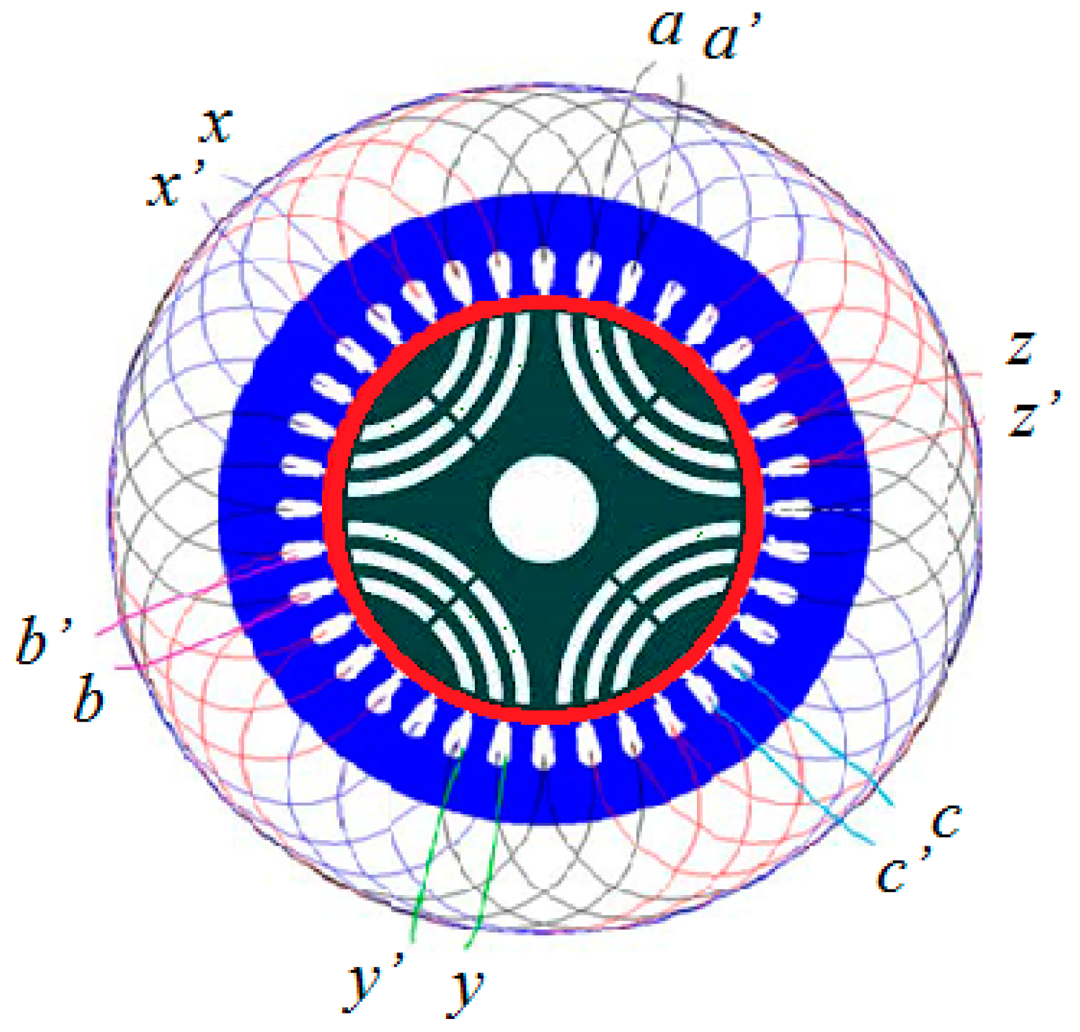
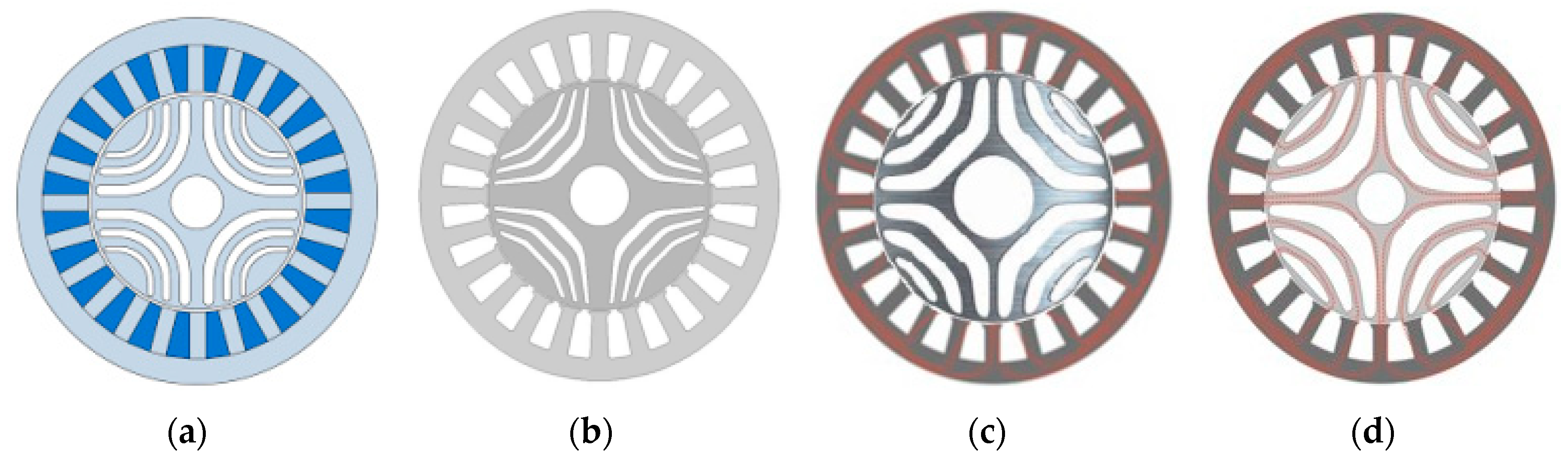
2.1. Initial Design of Six-Phase Synchronous Reluctance Motor

In order to demonstrate the two-step optimization processes of a motor, the six-phase synchronous reluctance motor with specifications of six-phase, 4-pole, 24-slot, 1800 r/min and 4 kW is investigated in this study. The abridged general view of the six-phase synchronous motor is shown in Figure 1. Table 1 is listed out the initial design parameters for the six-phase synchronous reluctance motor. The initial design of the motor consists of a stator with 24 stator slots which carry two-layer windings as shown in Figure 1 and Table 1. The six labels of six phases in the six-phase synchronous reluctance motor shown in Figure 1 are phase a, phase b, phase c, phase x, phase y and phase z with respect to six sets of stator windings with two outlet line ends as a, a’, b, b’, c, c’, x, x’, y, y’, z, z’. The better design of the six-phase synchronous reluctance motor is based on the good design procedures and calculations as follows.
The layout of a winding in electric machine affects magneto-motive force (MMF) distribution, which results in voltage as back electromotive force (back-EMF), machine performance and torque ripple. In application, the machine windings are comprised by wire-wound coils of one or more turns placed in slots arranged to constitute either single-layer or double-layer windings [19]. A double-layer winding results in a better back-EMF waveform than a single-layer winding [19]. Therefore the double-layer winding including the lap and concentric windings is used in this paper. The fundamental winding factors proposed by Hwang et al. [23] were found to be 0.959 for lap winding and 0.945 for concentric winding. The fundamental winding factor in this paper adopts 0.959 for lap winding to raise back-EMF [23].

2.2. Optimization Models with Multi-Objective Functions

The general minimum problem with multi-objective optimization can be written as follows:
min F 1 ( R ( v 1 ) ) = F 1 ( r 1 ( v 1 ) , r 2 ( v 1 ) , , r k ( v 1 ) ) , s t v 1 V 1  
where r 1 ( v 1 ) , r 2 ( v 1 ) and r 3 ( v 1 ) present the function of minimum stator iron cost, the function of minimum torque ripple and the function of minimum stator winding cost, respectively.
The general maximum problem with multi-objective optimization can be written as follows:
max F 2 ( S ( v 2 ) ) = F 2 ( s 1 ( v 2 ) , s 2 ( v 2 ) , , s k ( v 2 ) ) , s t v 2 V 2  
where s 1 ( v 1 ) , s 2 ( v 1 ) and s 3 ( v 1 ) present the function of maximum efficiency, the function of maximum power factor and the function of maximum output torque, respectively. The integer k is the number of objective function. V 1 and V 2 are the two feasible sets of known vectors. Two feasible sets are defined by some known constraint functions. In addition, two vector-valued objective functions are defined as R : V 1 k , R ( v 1 ) = ( r 1 ( v 1 ) , r 2 ( v 1 ) , , r k ( v 1 ) ) T and S : V 2 k , S ( v 2 ) = ( s 1 ( v 2 ) , s 2 ( v 2 ) , , s k ( v 2 ) ) T . Two images of V 1 and V 2 are indicated by W 1 k and W 2 k . Two elements v 1 * V 1 and v 2 * V 2 are called the feasible solutions. The Pareto frontier [13,14,15] is the set of choices which optimizes a system. The potentially optimal solutions can be made on focused tradeoffs within these constrained sets of parameters in the initial condition rather than needing to consider the full ranges of parameters. In order to speed-up search time and obtain better parameters, the BCO [17,18] is adopted to search for optimal parameters. In order to speed-up convergence, an altered BCO algorithm [17,18] depends in its implementation as follows:
δ n , j b = ρ n , j λ n , j b + φ n , i [ λ n , i b λ n , j ] ,    n = 1 ,    2 ,    j = 1 , 2 , , J ,    m = 1 , 2 , , M  
ρ n , j = ρ n , j 1 + ϕ n , j ( 1 ρ n , j 1 ) , n = 1 , 2 ,    j = 1 , 2 , , J  
where λ n , j is a food source selected randomly. j is a randomly chosen dimension. φ n , j is a random number between −1 and 1. ϕ n , j is a random number between 0 and 1. δ n , j b is the best solution among the neighbors of λ n , j b and itself. When it arrives the region of λ n , j , it examines all of the food sources in Nn. It chooses the best one, λ N n , j b to improve. ρ n , j is an acceleration factor, which can quickly search for the best solution. The fitness of a solution f i t ( λ n , j ) can be calculated from its objective function value f j ( λ n , j ) [17,18] by:
f i t ( λ N n , j b ) = max ( f i t ( λ N n , j 1 ) , f i t ( χ N n , j 2 ) , , f i t ( χ N n , j n s ) ) ,    j = 1 , 2 , , J  
By using the fitness values of the solutions in altered BCO algorithm, the probability value p j , which is really a roulette wheel selection mechanism, can be obtained [17,18] by:
p j = f i t j ( λ N n , j ) / i = 1 n s f i t i ( λ N n , j i ) ,    j = 1 , 2 , ,    J  
Therefore, recruiting more onlookers to richer sources, positive feedback behavior appears. After producing the new candidate food source δ n , j , its profitability is calculated. Then, a greedy selection is applied between δ n , j and λ n , j .

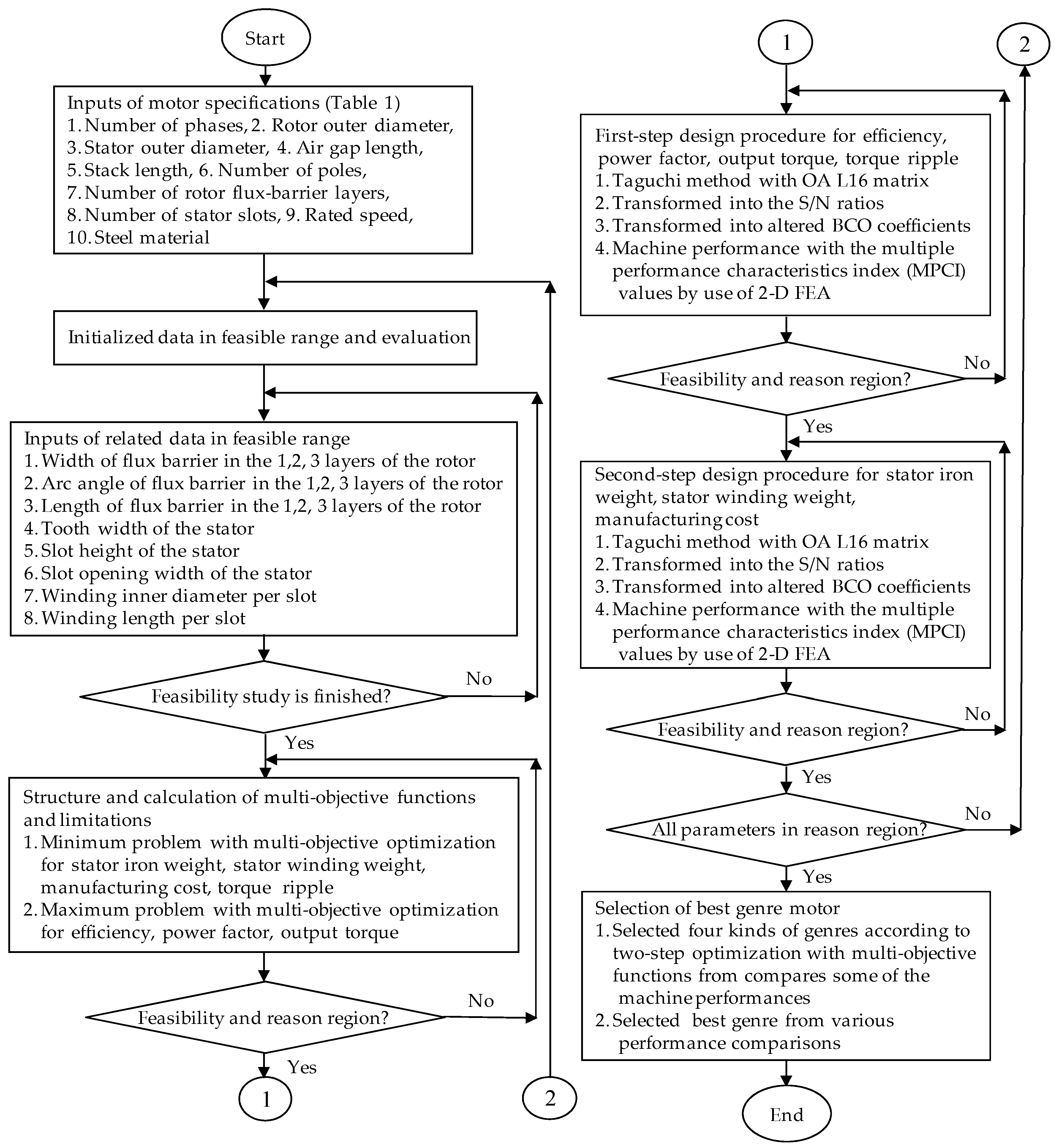
2.3. Two Step Procedures of Optimization Design

By using minimum and maximum problems with multi-objective optimizations as well as altered BCO algorithm, two step procedures of optimization design in the six-phase synchronous reluctance motor with respect to the stator and the rotor regions can be represented as follows.

2.3.1. The First-Step Procedure

In the first-step optimized procedure, the optimization design with multi-objectives functions is maximized efficiency, maximized power factor, maximized output torque, and minimized torque ripple by use of Equations (1) and (2). In order to fast search the optimized value, the Taguchi method [19,20] is adopted to optimize the machine parameter of performances characteristics in electrical discharge machining (EDM). The orthogonal array (OA) in the experimental designs proposed by Taguchi [19,20] played a central role in the development of Taguchi method. The numerical experiments by use of the standard Taguchi method with OA L16 matrix is presented in Table 2. Then, the experimental results by use of a standard Taguchi method with OA L16 matrix from Table 2 can be transformed into a signal-to-noise (S/N) ratio. The S/N ratio is used to measure the declination of the display characteristics from the desired values. The S/N ratio in the category of performance characteristics can be separated into the lower-the-better, the higher-the-better, and the nominal-the-better [19,20]. Furthermore, a lot of parameters of the experimental results presented in Table 3 are transformed into the S/N ratios and altered BCO coefficients based on altered BCO analysis [17,18].
Hence, the optimized level of the process parameters with maximized value is related to the level with the highest S/N ratio, and the optimized level of the process parameters with minimized value is related to the level with the lowest S/N ratio. Then, the machine performance with the multiple performance characteristics index (MPCI) values in the OA L16 matrix experiments presented in Table 3 can be obtained by use of 2-D FEA. Figure 2 denoted the MPCI values for each factor with respect to their related levels. To conduct the optimization process, five rotor geometrical parameters, which can affect the machine performances, are selected as presented in Figure 2. The five control factors with respect to their related levels are presented in Table 2, where A is the barrier width of the rotor in the inner layer in mm (levels 4.0, 4.2, 4.4 and 4.6), B is the barrier width of the rotor in the middle layer in mm (levels 3.0, 3.2, 3.4 and 3.6), C is the barrier width of the rotor in the outer layer in mm (levels 2.0, 2.2, 2.4 and 2.6), D is the barrier arc angle of the rotor for every barrier layer in degree (levels 18, 20, 22 and 24), and E is the barrier length of the rotor in mm (levels 20, 22, 24 and 26). It is noted in Figure 3 that the best combination of design parameters with maximization is determined to be (A1B3C1D2E4). The performance of the optimized motor was obtained by use of 2-D FEA again.

2.3.2. The Second-Step Procedure

In the second-step optimization procedure, the optimization design with multi-objectives functions is the minized manufacturing cost with respect to the stator iron weight, the stator winding weight and the stator slot shape by use of Equation (1). In order to fast search the optimized configuration, the Taguchi method [19,20] is adopted to optimize the machine parameter of performances characteristics in EDM. The numerical experiments by use of the standard Taguchi method with OA L16 matrix is presented in Table 4. Then, the experimental results by use of OA L16 matrix from Table 4 can be transformed into the S/N ratio. The S/N ratio is used to measure the declination of the display characteristics from the desired values. The S/N ratio in the category of performance characteristics can be separated into the lower-the-better, the higher-the-better, and the nominal-the-better [19,20]. Furthermore, the experimental results shown in Table 5 are transformed into the S/N ratios and altered BCO coefficients based on altered BCO analysis [17,18]. Therefore, the optimal level of the process parameters is the level with the lowest S/N ratio. Meantime, the machine performance with the MPCI values in the OA L16 matrix experiments can be obtained by use of 2-D FEA as shown in Table 5. Figure 3 shows the MPCI values for five control factors with respect to their related levels. The five control factors and their related levels are presented in Table 4, where A is the tooth width of the stator in mm (levels 8.0, 9.0, 10.0 and 11.0), B is the slot height of the stator in mm (levels 15.0, 15.5, 16.0 and 16.5), C is the slot opening width of the stator in mm (levels 9.0, 9.5, 10.0 and 10.5), D is the winding inner diameter per slot in mm (levels 0.4, 0.6, 0.8 and 1.0), and E is the winding length per slot in mm (levels 92, 94, 96 and 98). The best combination of design parameters with minimization presented in Figure 3 is determined to be (A3B4C2D1E3). The performance of the optimized motor was obtained by use of 2-D FEA again. These factors are related to efficiency, power factor, output torque and torque ripple because of flux action in the stator and the rotor [1].

3. Results

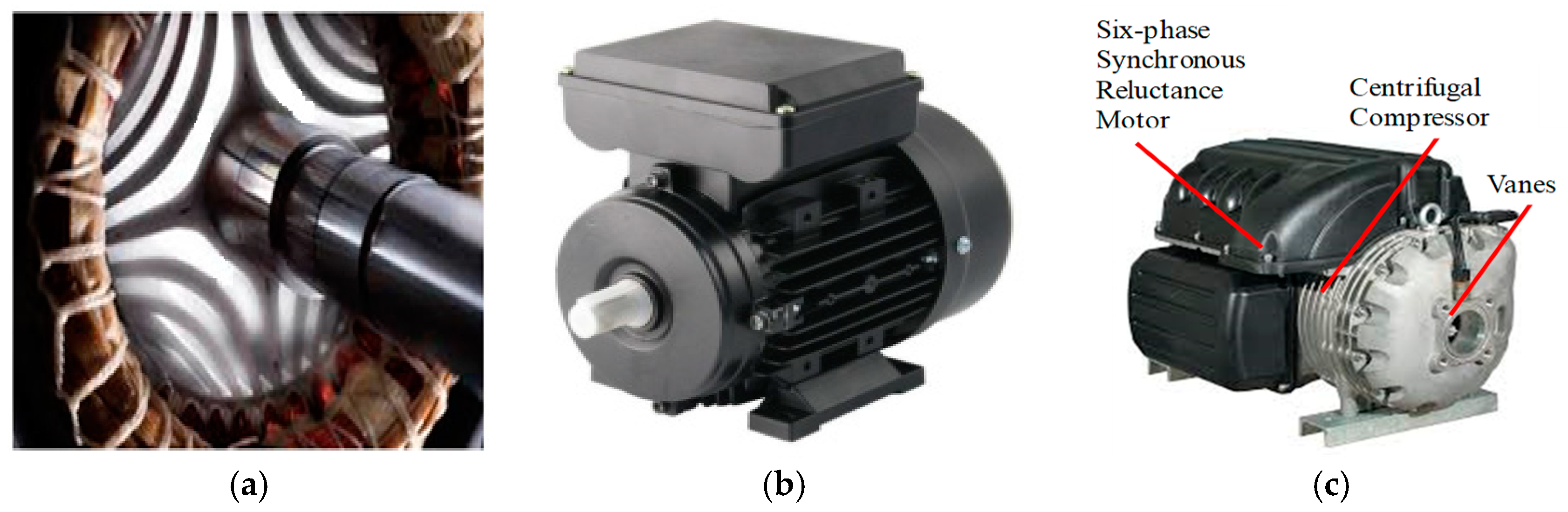
3.1. Experimental Tests

Total experimental results transformed into the S/N ratios and altered BCO coefficients based on altered BCO analysis are shown in Table 3 and Table 5. The S/N ratio is used to determine the deviation between the experimental value and the desired value. The summary performance results according to Table 3 and Table 5, Figure 2 and Figure 3 are presented in Table 6. The performance of the optimized motor was obtained by use of 2-D FEA again. To illustrate the process of the proposed optimuzation design, the flowchart diagram of two-step optimization design procedures with multi-objective functions is shown in Figure 4. The results of machine performance from two-step optimization design with respect to five control factors are presented in Table 6. Table 6 compares some of the machine performances from selected four kinds of genres according to two step optimization with multi-objective functions. Here, the machine performances such as iron weight, winding weight, manufacturing cost, power factor, efficiency, output torque and torque ripple are summarized in Table 6.
Main key results for four configurations by observation can be explained as follows.
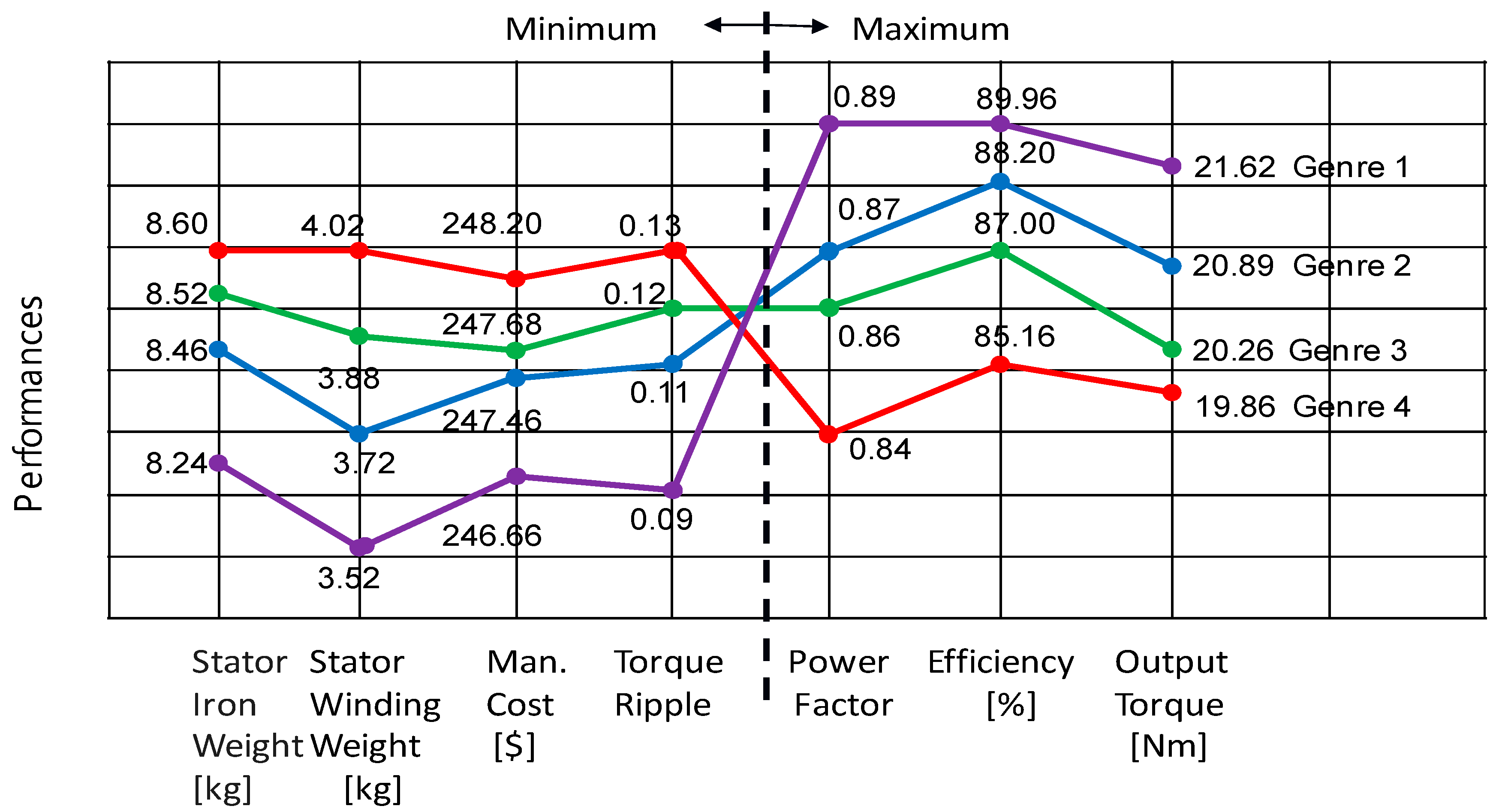
  • The weight of iron in Genre 1 is the lowest value as the 8.24 kg.
  • The weight of winding in Genre 1 is the lowest value as the 3.52 kg.
  • The manufacturing cost in Genre 1 is the lowest value as the $246.66.
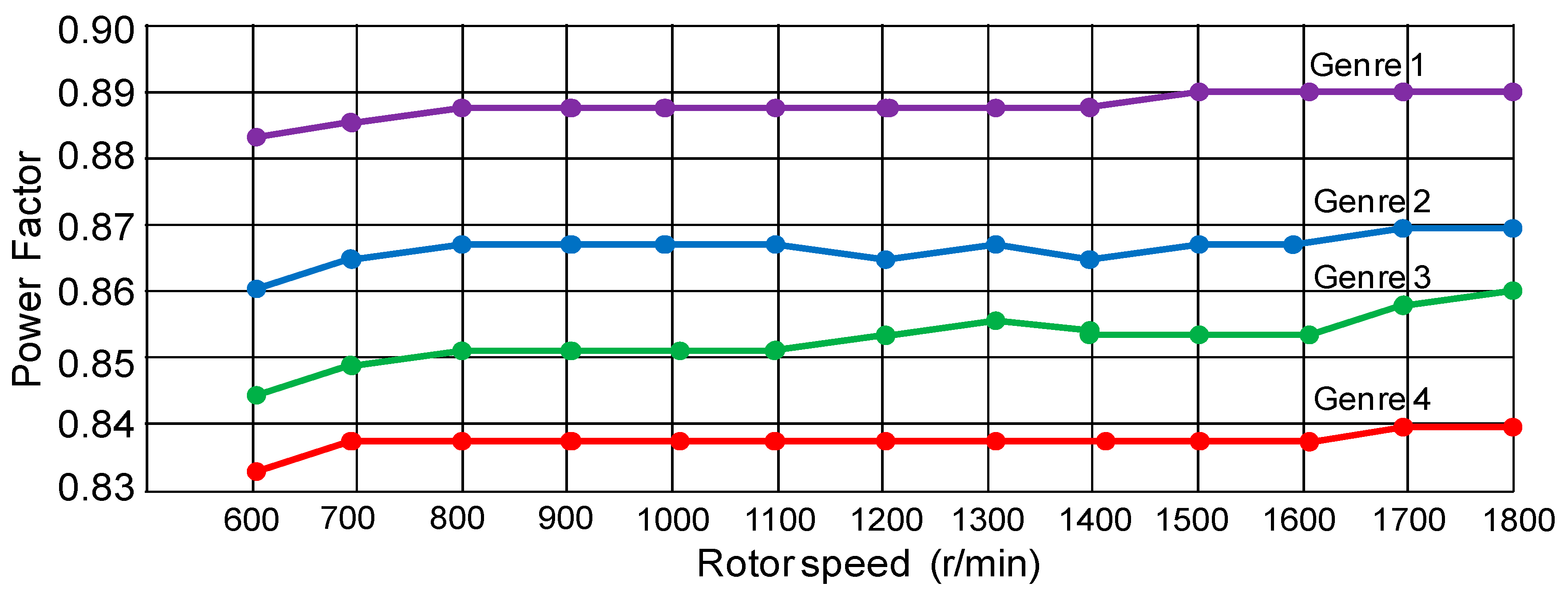
  • The power factor in Genre 1 is the highest value as the 0.89.
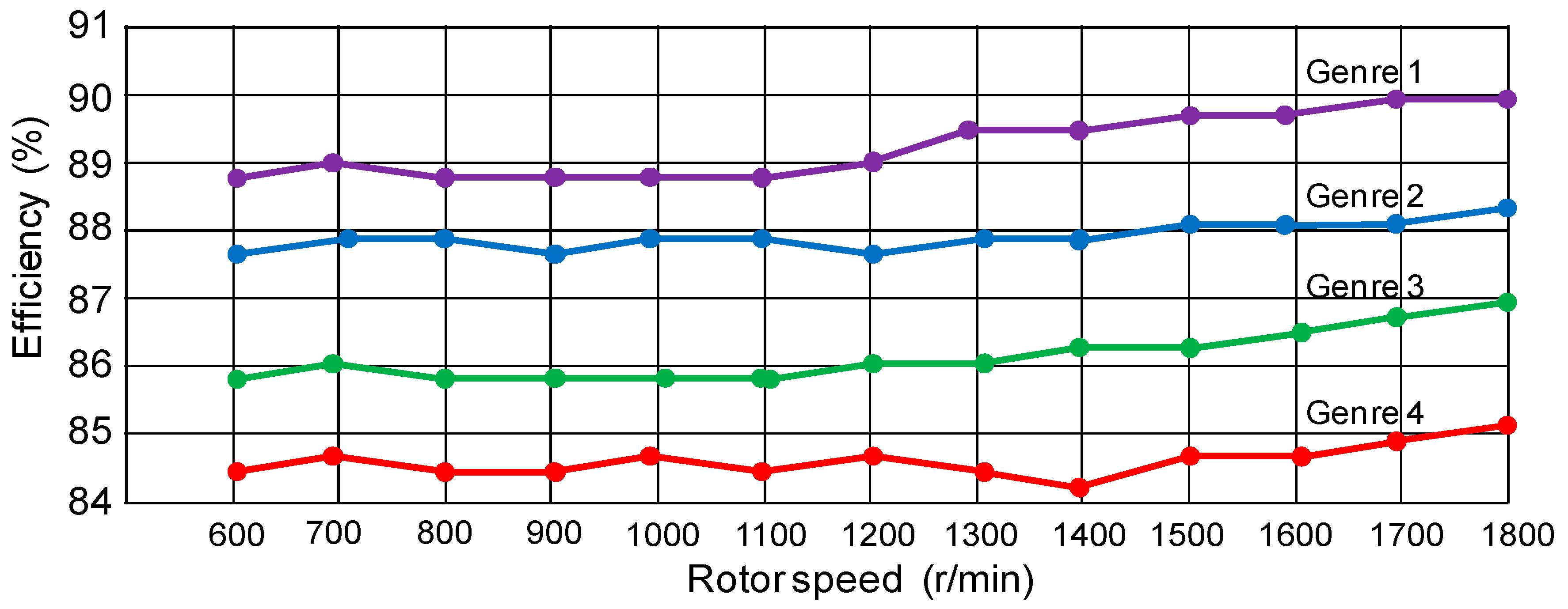
  • The efficiency in Genre 1 is the highest value as the 89.96%.
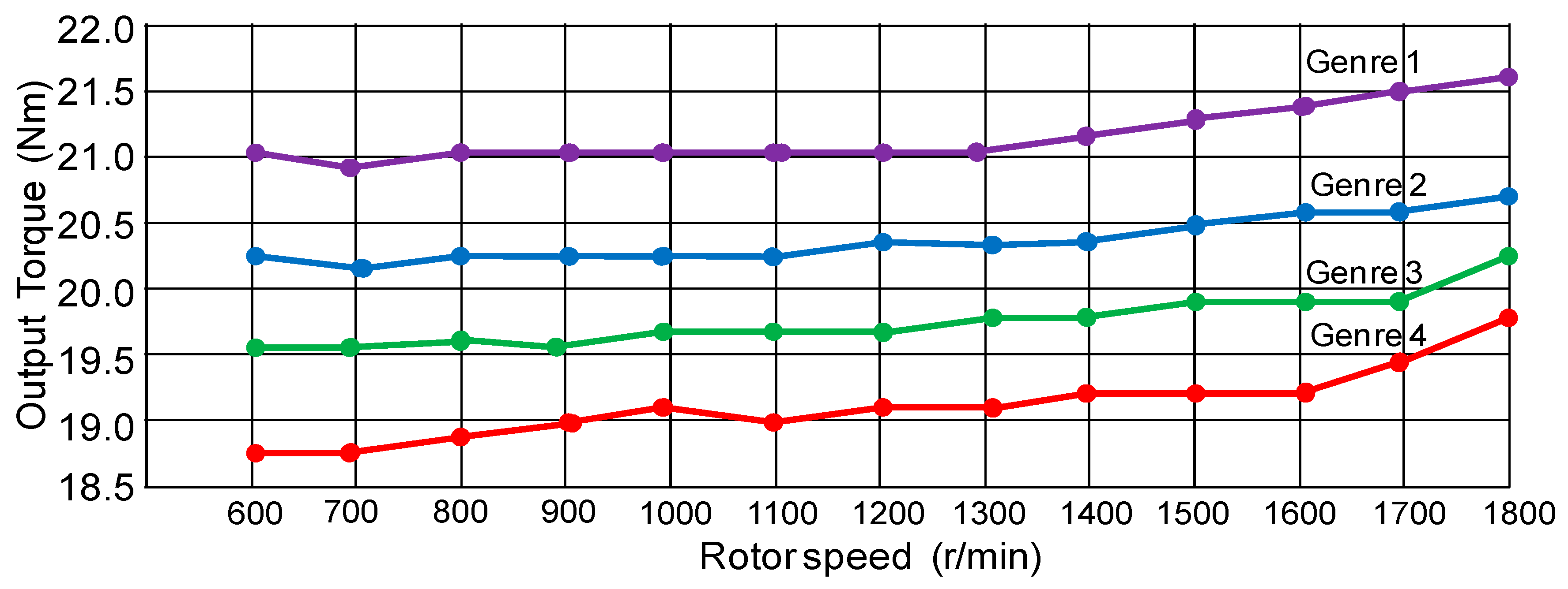
  • The output torque in Genre 1 is highest value as the 21.62 Nm.
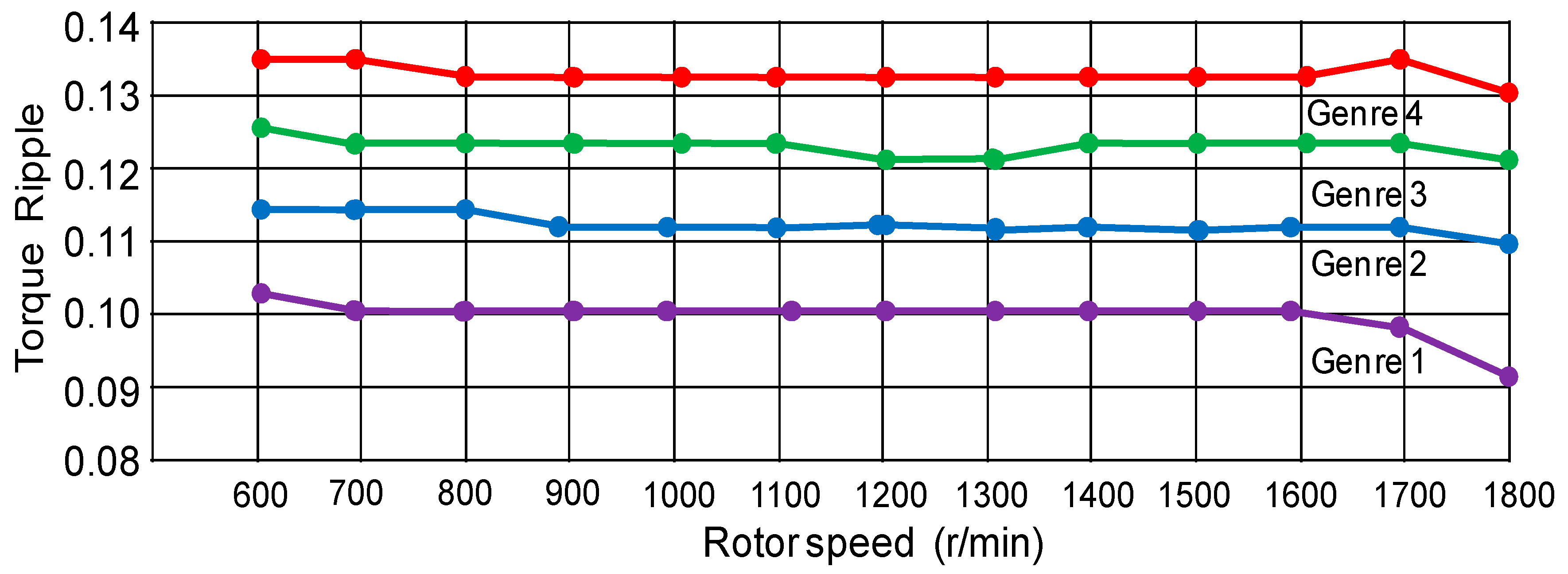
  • The torque ripple in Genre 1 is lowest value as the 0.09.
Comparing to all performances for four kinds of configurations shown in Table 6, the genre 1 of six-phase synchronous reluctance motor was selected optimization in the two-step optimal design with multi-objective functions. In addition, the tested results of efficiency, power factor, output torque and torque ripple for the four kinds of six-phase synchronous reluctance motors mounted to centrifugal compressor with various speeds are shown in Figure 5, Figure 6, Figure 7 and Figure 8, respectively. In summary, it is seen that the two-step optimal design with multi-objective functions can raise efficiency, power factor, output torque and reduce torque ripple from experimental results shown in Figure 5, Figure 6, Figure 7 and Figure 8.
The line chart of seven kinds of performances in four kinds of configurations of six-phase synchronous reluctance motors listed in Table 6 is shown Figure 9. It is very obvious that many characteristic performances in the genre 1 of six-phase synchronous reluctance motor is superior to the genres 2, 3 and 4 through the optimal design with multi-objective functions by use of the altered BCO and the Taguchi method combined with FEA.

3.2. Experimental Results

Full cross-section views in four kinds of configuration of six-phase synchronous reluctance motor as genre 1, genre 2, genre 3 and genre 4 is shown in Figure 10 according to present in Table 6. The chosen 4 kinds of six-phase synchronous reluctance motor through optimization design with multi-objective functions have some better performances. Magnetic flux with FEM analysis solutions after two-step optimization design in genre 1 of six-phase synchronous reluctance motor is shown in Figure 11, where Figure 11a is the full cross-section view of three-dimensional diagram at stator and windings, and Figure 11b is the full cross section and quarter cross section of two-dimensional diagram at stator and rotor. It is obvious that the genre 1 of six-phase synchronous reluctance motor has less magnetic saturation effect via optimization design with multi-objective functions. Finally, the completed photo picture of six-phase synchronous reluctance motor is shown Figure 12. The views of stator, rotor and winding, combination and six-phase synchronous reluctance motor mounted to a centrifugal compressor are shown in Figure 12a–c, respectively.

4. Discussions

The whole design process with two step design procedures based on multi-objective functions by use of the altered BCO and the Taguchi method combining with 2-D FEA is presented in Figure 4. In general, the execution of two step procedures requires a great calculation time. By use of the altered BCO and the Taguchi method, the execution of two step procedures reduces the calculation time by a lot. Meantime, the results of machine performance from two-step optimization design with respect to five control factors are presented in Table 6. Table 6 lists some selected successful machine performance features (iron weight, winding weight, manufacturing cost, power factor, efficiency, output torque and torque ripple) from four kinds of genres according to two step optimization designs with multi-objective functions. Better machine performance, and the corresponding optimization configurations can be easily found in Table 6. Therefore, the proposed two step design procedures based on multi-objective functions by use of the altered BCO and the Taguchi method combining with 2-D FEA is a very efficient and better approach in the robust design of a high-performance motor.

5. Conclusions

This paper has presented an optimization design with multi-objective functions by use of altered BCO method and Taguchi method combining with FEA on a six-phase synchronous reluctance motor applied to centrifugal compressor.
The main contributions and differences between this study and other studies are that the proposed methodologies for determining some operational regions with multi-objective functions have some features as: (1) a two-step optimization procedure, which depends mainly on the stator and rotor regions, focusing on cost and efficiency, has been successfully achieved; (2) the maximization of efficiency, power factor and output torque in the first-step design have been accomplished; (3) the minimization of manufacturing cost with respect to stator iron weight and stator winding weight and other installed cost in the second-step design has been finished; (4) the two step optimization of a six-phase synchronous reluctance motor has been successfully applied to a centrifugal compressor from the experimental results; and (5) an optimization design with multi-objective functions by use of the altered BCO and Taguchi method combined with FEA has been successfully applied in a six-phase synchronous reluctance motor. Finally, the experimental results of this paper confirm the effectiveness of the proposed technique for obtaining lower manufacturing cost, lower torque ripple, higher efficiency and higher power factor, less magnetic saturation effect and other better performance characteristics. Moreover, in the future this technique could be applied to solve multi-objective optimization problems for any electromagnetic device.

Author Contributions

C.-H.L. conceived and designed the system and experiments; C.-H.L. performed the software programs and the experimental tests; C.-H.L. analyzed the data for writing the paper; C.-H.L and C.-C.H. revised the paper.

Funding

This research was funded by Ministry of Science and Technology of Taiwan (Project MOST 106-2221-E-239-015).

Acknowledgments

This work was supported by the Ministry of Science and Technology under grant numbers MOST 106-2221-E-239-015.

Conflicts of Interest

The authors declare no conflict of interest.

References

  1. Leon, J.I.; Lopez, O.; Franquelo, L.G.; Doval-Gandoy, J.; Vazquez, S.; Alvarez, J.; Freijedo, F.D. Multilevel multiphase feedforward spacevector modulation technique. IEEE Trans. Ind. Electron. 2010, 57, 2066–2075. [Google Scholar] [CrossRef]
  2. Apsley, J.M.; Gonzalez-Villasenor, A.; Barnes, M.; Smith, A.C.; Williamson, S.; Schuddebeurs, J.D.; Norman, P.J.; Booth, C.D.; Burt, G.M.; McDonald, J.R. Propulsion drive models for full electric marine propulsion systems. IEEE Trans. Ind. Appl. 2009, 45, 676–684. [Google Scholar] [CrossRef]
  3. Kim, Y.H.; Lee, J.H. Optimum design criteria of an ALA-SynRM for the maximum torque density and power factor improvement. Int. J. Appl. Electromagn. Mech. 2017, 53 (Suppl. 2), 279–288. [Google Scholar] [CrossRef]
  4. Chai, W.; Zhao, W.; Kwon, B. Optimal design of wound field synchronous reluctance machines to improve torque by increasing the saliency ratio. IEEE Trans. Magn. 2017, 53. [Google Scholar] [CrossRef]
  5. Wang, T.; Fang, F.; Wu, X.; Jiang, X. Novel filter for stator harmonic currents reduction in six-step converter fed multiphase induction motor drives. IEEE Trans. Power Electron. 2013, 28, 498–506. [Google Scholar] [CrossRef]
  6. Zhao, H.; Zhang, J.; Wang, X.; Wang, Q.; Liu, X.; Luo, Y. A design method for cage induction motors with non-skewed rotor bars. IEEE Trans. Magn. 2014, 50, 7019004. [Google Scholar]
  7. Fathy, M.N.I.; Sergeant, P.; Rashad, E. Simple design approach for low torque ripple and high output torque synchronous reluctance motors. Energies 2016, 9, 942. [Google Scholar]
  8. Fathy, M.N.I.; Sergeant, P.; Rashad, E. Performance comparison of conventional synchronous reluctance machines and PM-assisted types with combined star–delta winding. Energies 2017, 10, 1500. [Google Scholar]
  9. Artetxe, G.; Paredes, J.; Prieto, B.; Martinez-Iturralde, M.; Elosegui, I. Optimal pole number and winding designs for low speed–high torque synchronous reluctance machines. Energies 2018, 11, 128. [Google Scholar] [CrossRef]
  10. Mittelstedt, M.; Hansen, C.; Mertiny, P. Design and multi-objective optimization of fiber-reinforced polymer composite flywheel rotors. Appl. Sci. 2018, 8, 1256. [Google Scholar] [CrossRef]
  11. Anwar, N.; Deng, H. A hybrid metaheuristic for multi-objective scientific workflow scheduling in a cloud environment. Appl. Sci. 2018, 8, 538. [Google Scholar] [CrossRef]
  12. Shen, Y.; Wang, X.; Chen, J. Wind power forecasting using multi-objective evolutionary algorithms for wavelet neural network-optimized prediction intervals. Appl. Sci. 2018, 8, 185. [Google Scholar] [CrossRef]
  13. Mathur, V.K. How well do we know Pareto optimality. J. Econ. Educ. 1991, 22, 172–178. [Google Scholar] [CrossRef]
  14. Kanbur, R. Pareto’s revenge. J. Soc. Econ. Dev. 2005, 7, 1–11. [Google Scholar]
  15. Barr, N. The Relevance of Efficiency to Different Theories of Society. In Economics of the Welfare State; Oxford University Press: Oxford, UK, 2012; pp. 46–51. [Google Scholar]
  16. Huang, Y.; Wang, H.; Khajepour, A.; Li, B.; Ji, J.; Zhao, K.; Hu, C. A review of power management strategies and component sizing methods for hybrid vehicles. Renew. Sustain. Energy Rev. 2018, 96, 132–144. [Google Scholar] [CrossRef]
  17. Karaboga, D.; Basturk, B. On the performance of artificial bee colony (ABC) algorithm. Appl. Soft Comput. 2008, 8, 687–697. [Google Scholar] [CrossRef]
  18. Lin, C.H. Modelling and control of six-phase induction motor servo-driven continuously variable transmission system using blend modified recurrent Gegenbauer orthogonal polynomial neural network control system and amended artificial bee colony optimization. Int. J. Numer. Model. 2016, 29, 915–942. [Google Scholar] [CrossRef]
  19. Hwang, C.C.; Chang, C.M.; Liu, C.T. A fuzzy-based Taguchi method for multi-objective design of PM motors. IEEE Trans. Magn. 2013, 49, 2153–2156. [Google Scholar] [CrossRef]
  20. Lin, C.H.; Hwang, C.C. Multiobjective optimization design for a six-phase copper rotor induction motor mounted with a Scroll compressor. IEEE Trans. Magn. 2016, 52, 9401604. [Google Scholar] [CrossRef]
  21. Yamazaki, K.; Suzuki, A.; Ohto, M.; Takakura, T.; Nakagawa, S. Equivalent circuit modeling of induction motors considering stray load loss and harmonic torques using finite element method. IEEE Trans. Magn. 2011, 47, 986–989. [Google Scholar] [CrossRef]
  22. Ahn, J.; Lee, D.; Park, G.J.; Kim, Y.J.; Kim, J.; Jung, S.Y. Numerical design compatibility of induction motor with respect to voltage and current sources. IEEE Trans. Magn. 2014, 50, 7019104. [Google Scholar] [CrossRef]
  23. Hwang, C.C.; Chang, C.M.; Hung, S.S.; Liu, C.T. Design of high performance flux switching PM machines with concentrated windings. IEEE Trans. Magn. 2014, 50, 4002404. [Google Scholar] [CrossRef]
Figure 1. Abridged general view of the six-phase synchronous motor.
Energies 11 02716 g001
Figure 2. The MPCI values for five control factors with respect to the corresponding levels.
Energies 11 02716 g002
Figure 3. The MPCI values for five control factors with respect to the corresponding levels.
Energies 11 02716 g003
Figure 4. Flowchart diagram of two-step optimal design procedures with multi-objective functions.
Energies 11 02716 g004
Figure 5. Line chart of comparisons of efficiency for 4 kinds of six-phase synchronous reluctance motors mounted to centrifugal compressor with various speeds.
Energies 11 02716 g005
Figure 6. Line chart of comparisons of power factor for 4 kinds of six-phase synchronous reluctance motors mounted to centrifugal compressor with various speeds.
Energies 11 02716 g006
Figure 7. Line chart of comparisons of output torque for 4 kinds of six-phase synchronous reluctance motors mounted to centrifugal compressor with various speeds.
Energies 11 02716 g007
Figure 8. Line chart of comparisons of torque ripple for 4 kinds of six-phase synchronous reluctance motors mounted to centrifugal compressor with various speeds.
Energies 11 02716 g008
Figure 9. Line chart of performances comparisons for 4 kinds of six-phase synchronous reluctance motors mounted to centrifugal compressor.
Energies 11 02716 g009
Figure 10. Full cross-section views in four genres of configurations of six-phase synchronous reluctance motor: (a) genre 1; (b) genre 2; (c) genre 3; (d) genre 4.
Energies 11 02716 g010
Figure 11. Magnetic flux with FEM analysis solutions after two-step optimization in genre 1 of six-phase synchronous reluctance motor: (a) full cross-section view of three-dimensional diagram at stator and windings; (b) full cross section and quarter cross section of two -dimensional diagram at stator and rotor.
Energies 11 02716 g011
Figure 12. Completed photo pictures of six-phase synchronous reluctance motor: (a) stator, rotor and winding; (b) combination; (c) six-phase synchronous reluctance motor mounted to a centrifugal compressor.
Energies 11 02716 g012
Table 1. Initial design of motor specifications.
ParameterValue
Number of phases6 (phase a, phase b, phase c, phase x, phase y, phase z)
Rotor outer diameter [mm]82
Stator outer diameter [mm]134
Air gap length [mm]0.5
Stack length [mm]84
Number of poles4
Number of rotor flux-barrier layers 3
Number of stator slots24
Rated speed [r/min]1800
Rated power output [kW]4
Steel material50CS600
Table 2. Orthogonal array (OA) L16 matrix by using Taguchi method and experimental results.
No.Control FactorEfficiency ηPower Factor φTorque Ripple γOutput Torque τ
ABCDE[%]--[Nm]
11111177.630.810.2118.60
21222278.150.820.1618.71
31333380.100.790.2018.94
41444480.630.820.1719.20
52123487.000.860.1219.86
62214380.200.810.1819.24
72341278.210.800.2418.12
82432189.960.890.0921.62
93134277.040.780.2718.46
103243185.160.840.1320.26
113312480.820.790.2319.28
123421378.700.810.1918.61
134142378.700.790.2018.62
144231488.200.870.1120.81
154324180.200.810.2519.18
164413279.460.800.1918.93
Table 3. Transformations matrix of S/N ratios, altered BCO coefficient and MPCI.
No.S/N RatioAltered BCO CoefficientMPCI
Efficiency ηPower Factor φTorque Ripple γOutput Torque τEfficiency ηPower Factor φTorque Ripple γOutput Torque τ
[%]--[Nm][%]--[Nm]
121.815.6−1.617.280.790.86−0.580.730.64
221.418.1−1.827.680.820.78−0.640.770.68
322.619.1−1.886.860.590.81−0.590.880.62
421.719.6−1.686.850.640.68−0.580.950.56
522.715.2−1.298.860.750.87−0.690.760.65
621.815.8−1.568.780.690.69−0.520.840.62
721.415.2−1.549.100.590.58−0.670.660.64
821.518.2−1.338.870.560.79−0.550.780.68
922.716.7−1.648.620.520.74−0.480.880.60
1022.819.8−1.688.820.820.82−0.950.690.67
1121.816.9−1.598.700.840.71−0.640.780.69
1222.515.9−1.498.940.820.66−0.590.660.61
1322.416.8−1.768.360.810.72−0.480.670.67
1421.817.5−1.588.920.710.85−0.570.730.66
1522.415.3−1.698.860.720.83−0.670.830.60
1621.318.8−1.948.680.680.89−0.630.760.58
Table 4. Orthogonal array (OA) L16 matrix by using Taguchi method and experimental results.
No.Control FactorStator Iron WeightStator Winding Weight Manufacturing Cost
ABCDE[kg][kg][$]
1111119.884.96258.20
2122229.464.44257.61
3133339.224.64252.82
4144449.025.02253.96
5212348.735.04249.12
6221439.004.44249.38
7234128.924.22248.68
8243218.463.72247.46
9313428.844.08249.18
10324318.604.02248.20
11331248.664.98248.98
12342138.704.68248.86
13414238.243.52246.66
14423148.523.88247.68
15432419.204.31248.58
16441329.364.20249.96
Table 5. Transformations matrix of S/N ratios, altered BCO coefficient and MPCI.
No.S/N RatioAltered BCO CoefficientMPCI
Stator Iron WeightStator Winding Weight Manufacturing CostStator Iron WeightStator Winding WeightManufacturing Cost
[kg][kg][$][kg][kg][$]
116.4019.6439.820.580.760.8600.66
216.1818.8639.910.480.680.8990.68
317.9418.9639.940.720.560.9560.69
417.6617.8838.920.680.500.9760.67
517.2416.8839.200.580.620.8040.64
616.1217.8238.820.620.660.6920.60
717.7817.4338.960.580.560.7240.61
816.8818.8638.880.540.660.7870.63
916.8616.6138.960.500.620.8680.68
1016.2918.2839.080.820.520.9720.69
1116.0418.9637.880.600.560.6460.59
1216.0216.6638.680.520.620.6240.58
1315.7615.8838.480.480.740.6560.61
1417.1216.8638.960.700.520.7380.64
1516.1819.8638.860.600.540.7980.63
1616.9615.6238.440.580.600.8490.66
Table 6. Comparative results of machine performance for four kinds of motors.
ConfigurationGenre 1Genre 2Genre 3Genre 4
Stator Iron Weight [kg]8.248.468.528.60
Stator Winding Weight [kg]3.523.723.884.02
Manufacturing Cost [$]246.66247.46247.68248.20
Power Factor [−]0.890.870.860.84
Efficiency [%]89.9688.2087.0085.16
Torque Ripple [−]0.090.110.120.13
Output Torque [Nm]21.6220.8120.2619.86

