Article

Thermal Performance Enhancement of a Cross-Flow-Type Maisotsenko Heat and Mass Exchanger Using Various Nanofluids

1
Facultad de Ingeniería, Universidad Autónoma de Yucatán, Av. Industrias No Contaminantes por Anillo Periférico Norte, Apdo. Postal 150, Cordemex, Mérida, Yucatán 97000, Mexico
2
School of Architecture, Harbin Institute of Technology; Key Laboratory of Cold Region Urban and Rural Human Settlement Environment Science and Technology, Ministry of Industry and Information Technology, Harbin 150001, China
3
Department of Mechanical Engineering, Faculty of Engineering and Technology, International Islamic University, Islamabad 44000, Pakistan
4
School of Engineering and Computer Science, University of Hull, Hull HU6 7RX, UK
*
Authors to whom correspondence should be addressed.
Energies 2018, 11(10), 2656; https://doi.org/10.3390/en11102656
Submission received: 17 September 2018 / Revised: 27 September 2018 / Accepted: 27 September 2018 / Published: 5 October 2018

Abstract

:
The incorporation of a Maisotsenko (M) Cycle into an indirect evaporative cooler has led to the achievement of sub-wet bulb temperature without any humidification, thus making it a possible green and sustainable alternative for handling the cooling load of a building. In this work, the thermal performance of a cross-flow heat and mass exchanger (HMX) is enhanced by the addition of nanoparticles in the wet channel because they significantly influence the heat and mass transfer characteristics of the base fluid. A governing model for the temperature and humidity variations of the HMX is numerically simulated. Initial benchmarking is achieved using water properties. Afterward, a comparative study is conducted using aluminum-oxide-, copper-oxide-, and titanium-oxide-based nanofluids. Enhancements of 24.2% in heat flux, 19.24% in wet bulb effectiveness, 7.04% in dew point effectiveness, 29.66% in cooling capacity, and 28.43% in energy efficiency ratio are observed by using alumina-based nanofluid as compared to water in the wet channel of the cross-flow HMX. Furthermore, a particle volume concentration of 1% and a particle diameter of 20nm are recommended for maximum performance.

1. Introduction

The global increase in CO2 levels and other environmental concerns (climate change, ozone layer depletion, etc.) have directed researchers to look for a substitute solution to meeting building cooling loads [1], which is conventionally dominated by the vapor-compression refrigeration cycle (VCRC) [2]. Despite their compactness and high coefficient of performance (COP), the use of high-power-consuming compressors and harmful chemical refrigerants makes VCRC the least favorable option for space cooling. To address this issue, studies have led towards an evaporative cooling system which uses the latent heat of vaporization of water for cooling purposes [3]. An evaporative cooling system is a low-carbon-emitting device [4] and has a natural refrigerant (i.e., water) [5]; therefore, it can provide an alternative solution to meeting building cooling requirements [6]. However, evaporative coolers face a technical barrier in overcoming enormous cooling loads because air cannot go below its wet bulb temperature while in direct contact with water [7].
Recent structural amendments and flow variations in indirect evaporative coolers (called the Maisotsenko or M Cycle) enabled them to achieve sub-wet bulb temperature without any moisture addition to the supply air provided to the occupant’s comfort zone [8]. After this, many studies were performed on the structural design of the Maisotsenko (M)-cycle-based heat and mass exchanger (HMX) to find the optimal geometric and flow parameters to yield its maximum performance. Analyses based on cross-flow [9], counter-flow [10,11], and hybrid configurations [12] of HMXs are reported in the literature. Khalid et al. [13] experimentally analyzed the performance of a cross-flow HMX under low-velocity conditions. They concluded that the performance of the HMX can be enhanced by using an efficient moisture-absorbing material in the wet channel. Zhan et al. [14] analyzed a cross-flow HMX through numerical simulation and found the optimal geometric and flow parameters of the HMX.
Zhan et al. [15], Anisimov et al. [16], and Pandelidis et al. [17] each provided a comparative study of different configurations of HMXs. Their results have shown that a counter-flow HMX offers high cooling effectiveness but yields lower values of cooling capacity to handle a large cooling load. In contrast, a cross-flow configuration has higher values of cooling capacity at the detriment of other performance parameters. Afterwards, researchers focused on improving the energy efficiency of the dew point evaporative cooler [18,19,20,21]. For this purpose, some other structural modifications [12] were also presented in the HMX to increase the performance parameters; however, these structural modifications only increase the manufacturing complexities of the design. In a recent work by Tariq et al. [11], the wet fluid was altered from a conventional evaporating medium (water) to an alumina-based nanofluid. Research [22] has shown that the nanofluid exhibited higher thermal properties (thermal conductivity, viscosity, mass diffusivity, thermal diffusivity) compared with the base fluid. These enhanced properties yield a higher convective heat transfer coefficient in the wet channel and, as a result, the heat exchanger is expected to achieve higher performance parameters. However, nanofluids bring more complexities of type, concentration, size, and shape of the particles, as suggested by Maheshwary et al. [23]. Considering this aspect, Tariq et al. [11] replaced the water evaporating medium with a nanofluid in the wet channel of the indirect evaporative cooler. This alteration of the evaporating medium was only conducted for a counter-flow configuration of the indirect evaporative cooler, and their results indicated that the overall system performance was increased by 9–19% in terms of the energy efficiency ratio. However, this work was quite limited [11] because it was only applied to a counter-flow heat exchanger and analysis was presented for just one type of nanofluid (alumina–water) for a single particle diameter and concentration. Therefore, this area requires further concentration; specifically, no analysis is available for a cross-flow configuration for different types, concentrations, and particle diameter of nanofluids. This analysis is important because a cross-flow configuration is preferred for commercial and residential installation [24] of indirect evaporative coolers. Additionally, the selection of the most appropriate type of nanofluid is also not well researched. Therefore, in this article, the preceding literature gap is addressed.
In this work, the performance of a cross-flow HMX is enhanced by altering the heat and mass characteristics of the evaporation medium (water) in the wet channel. The alteration is achieved by the introduction of nanoparticles into the water. Some other studies have been conducted on these aforementioned complexities in different thermal systems including heat exchangers [25] and electronic cooling [26], etc. However, no work has been presented on the usage of nanoparticles in the wet channel of a cross-flow Maisotsenko-based HMX for performance enhancement.
The geometric and flow configuration of a cross-flow heat and mass exchanger is presented in Figure 1. The psychrometric representation is presented by the authors in [15]. In this work, an advancement is proposed for the conventional cross-flow HMX by using nanofluid in the wet channel (serving as an evaporating medium) of the cross-flow HMX. Analysis is carried out for three different types of nanoparticles—aluminum oxide, copper oxide, and titanium oxide—using a mathematical model developed for the cross-flow HMX. The heat and mass transfer characteristics (Nusselt number and Sherwood number) in the wet channel are calculated by incorporating the nanoparticle type, volume fraction, size, shape, and its Brownian motion. The resulting ordinary differential equations are simulated on MATLAB to find the temperature and humidity distribution of the channels with and without the addition of nanoparticles. A comparative study is conducted in which the influence of the type of nanoparticle on the HMX performance parameters (cooling effectiveness, cooling capacity, and Energy Efficiency Ratio (EER)) is conducted. Afterwards, analysis is carried out for varying particle volume fraction and particle diameter of one selected nanofluid.

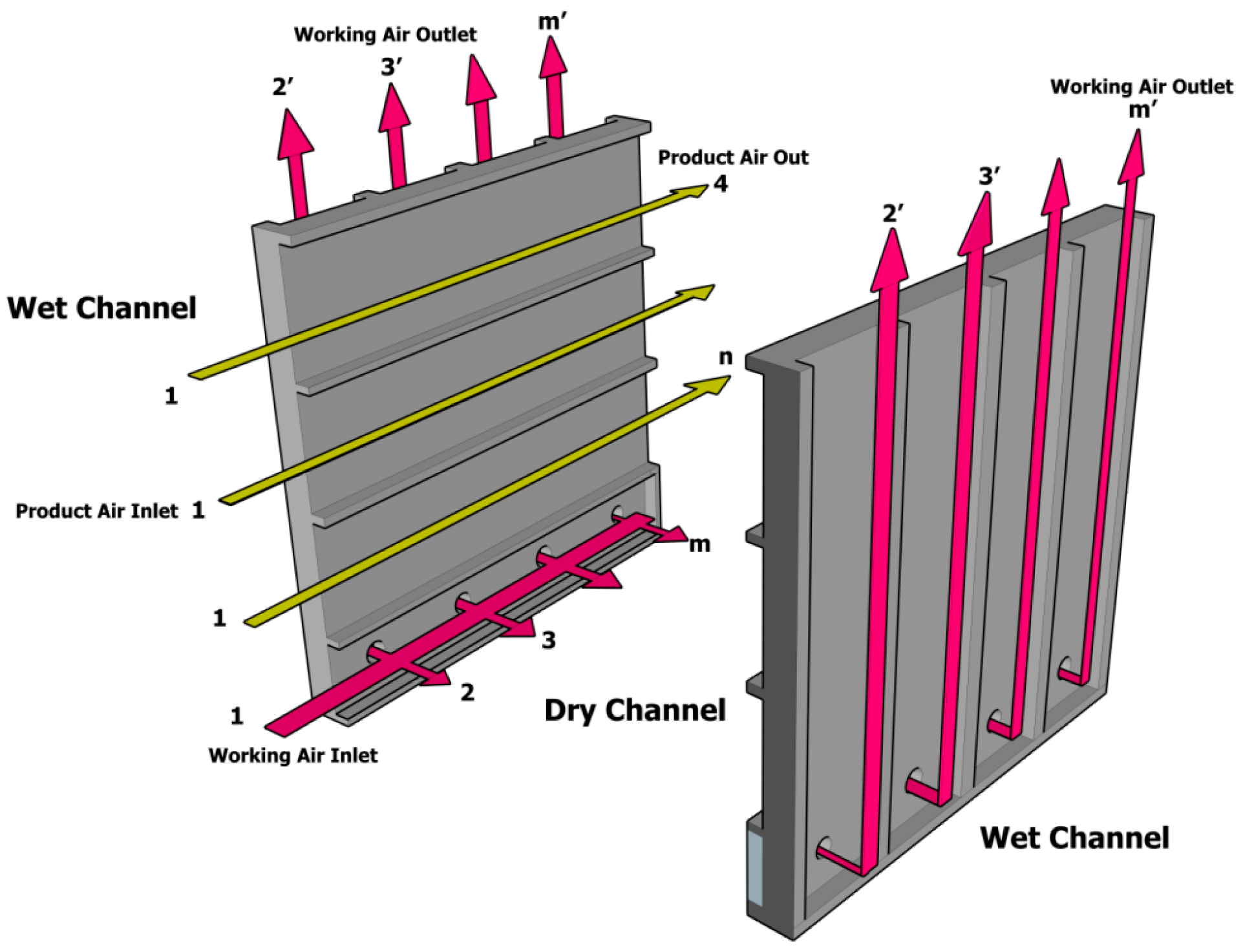
2. Mathematical Description

Energy and mass balance laws were applied to each channel to describe the mathematics of the heat and mass exchanger. For this purpose, a differential control volume (see Figure 2) was selected which shows the working air and the product air channel. The mathematical model of this system was developed for a single channel of each dry and wet section for numerical simplification. The working air in the dry channel moves in the x direction whereas the working air in the wet channel moves in the y direction. Therefore, the mathematical model was developed to incorporate two one-dimensional flows. Here, all flows are considered to be steady-state. The mixing and spatial distributions of nanoparticles are considered uniform. The properties of the fluid are considered to be consistent at any cross section of the dry and wet channels. The entry hydrodynamic layer is ignored. The water vapor is assumed to be uniformly distributed in the wet channel. Furthermore, considering the applied nature of the problem, it is also assumed that there is no loss of nanoparticles from the water film to the working air, the nanofluid is stable, the distribution of the nanoparticles in the base fluid is consistent, and there are no problems with sedimentation of nanoparticles. Zhan et al. [14] showed that some of these assumptions do not have any significant influence on the overall performance of the HMX.

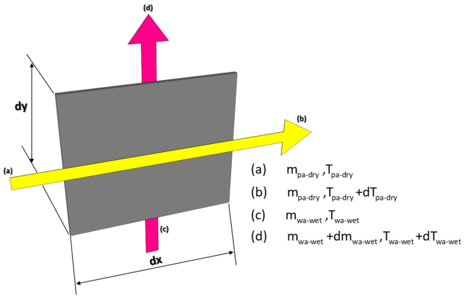
2.1. Energy and Mass Balance Laws

The energy balance works on the basis that the change in enthalpy of the fluid is equal to the corresponding mode of heat transfer. The product air in the dry channel undergoes a sensible change in temperature and this thermal change is caused because heat is transferred to the adjacent wet channel through the convective mode of heat transfer. Similarly, the enthalpy change of the working air in the wet channel is caused by heat addition from the product air channel. Based on this, the temperature and humidity distribution equations of the air channels are given in Table 1.
Equations (1), (2), and (4) (Table 1) are first-order ordinary differential equations (ODEs) having three unknowns, i.e., the temperature of product air, and the temperature and humidity of working air in the wet channel. The inlet temperatures of the product air and working air and the humidity of the working air are considered to be the boundary conditions for Equations (1), (2) and (4). Furthermore, the mixer equation from the working air dry channel to the working air wet channel was solved using the method adapted by Demis et al. [27].

2.2. Calculation of Heat and Mass Transfer Parameters of the HMX

The physics of the air–water–nanoparticle mixture are such that the properties of the evaporating medium (which is water originally) are altered by the properties of the nanofluid. Consider the fact that the multiphase nature of particulate flow requires rigorous mathematical models [28]; furthermore, simplified models [29] are extensively employed to simulate the nature of similar flows in the limit of low concentration and small particle diameters. The current investigation involving nanofluids remains well within the prescribed limits for the reliable applicability of simplified models. Therefore, this study uses a homogeneous model approach for the presented results. Maxwell [30] correlation was used to find the effective thermal conductivity of the nanofluid. The viscosity of the nanofluid was calculated using the correlation proposed by Corcione [31] considering the limitations of the particle size, particle volume fraction, and the working temperature. Other thermophysical quantities including the specific heat, density, mass diffusivity, and thermal diffusivity of the nanofluid were calculated using a weighted-average method considering the concentration of nanoparticles in the base fluid [29]. Finally, the convective heat transfer coefficient of the water film was calculated using the correlation provided by Xuan and Li [32]. Further details of this procedure are shown in Table 2. The convective heat transfer coefficient of the dry and wet air, along with the convective mass transfer coefficient between the wet air and evaporating medium, is shown by the authors in [14,15].

2.3. Performance Parameters

The cooling effectiveness of the HMX was calculated using
ε WB = T DB wa dry , inlet T DB wa , outlet T DB wa dry , inlet T WB wa dry , inlet
ε DP = T DB wa dry , inlet T DB wa , outlet T DB wa dry , inlet T DP wa dry , inlet
The cooling capacity was calculated using
Ψ = m wa dry ( H wa dry , inlet H wa , outlet )
The performance of the HMX was gauged based on the wet bulb effectiveness, dew point effectiveness, cooling capacity, and energy efficiency ratio [42]. The Energy Efficiency Ratio (EER) was calculated using the ratio of cooling capacity to the total required input power. The required input power was evaluated by accounting for the major losses in the channels such as friction factor. The performance of the HMX was also deduced by comparing water as the working fluid in the wet channel with the nanofluid. Therefore, each of the performance indices (PIs) for using nanofluid in the wet channel were compared with the performance indices of using water in the wet channel and are represented by the Performance Enhancement Ratio (PER).
PER ( % ) = PI nf PI w PI w × 100

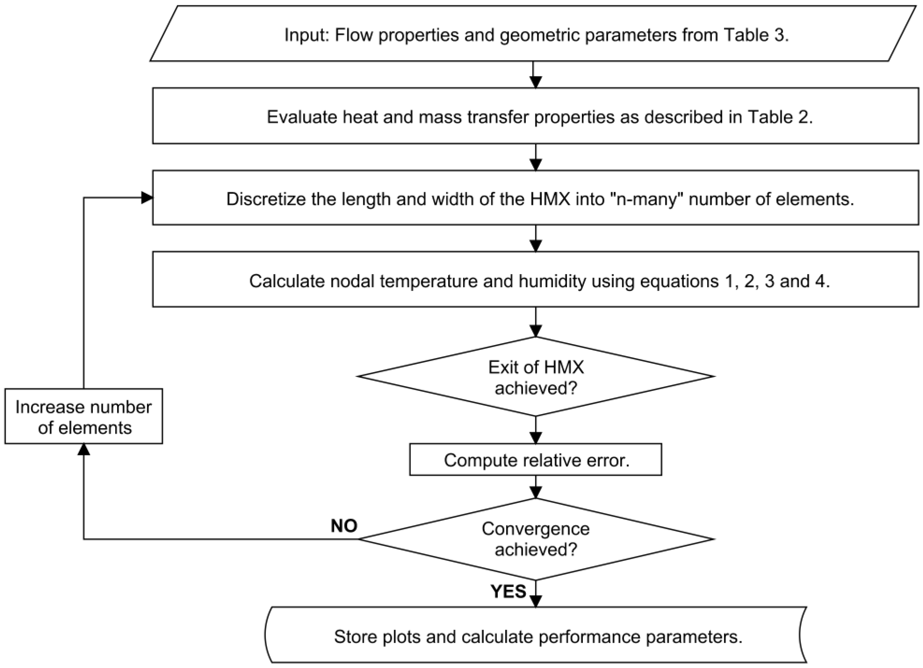
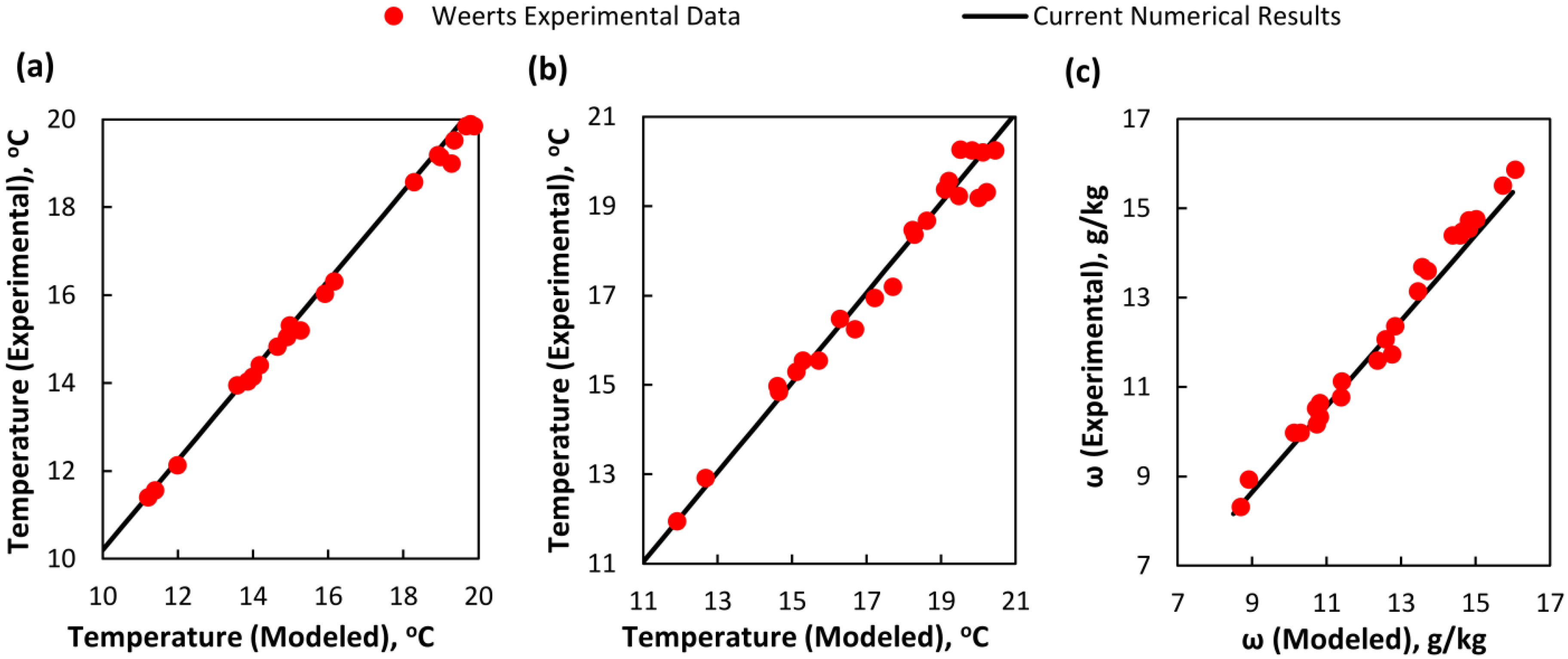
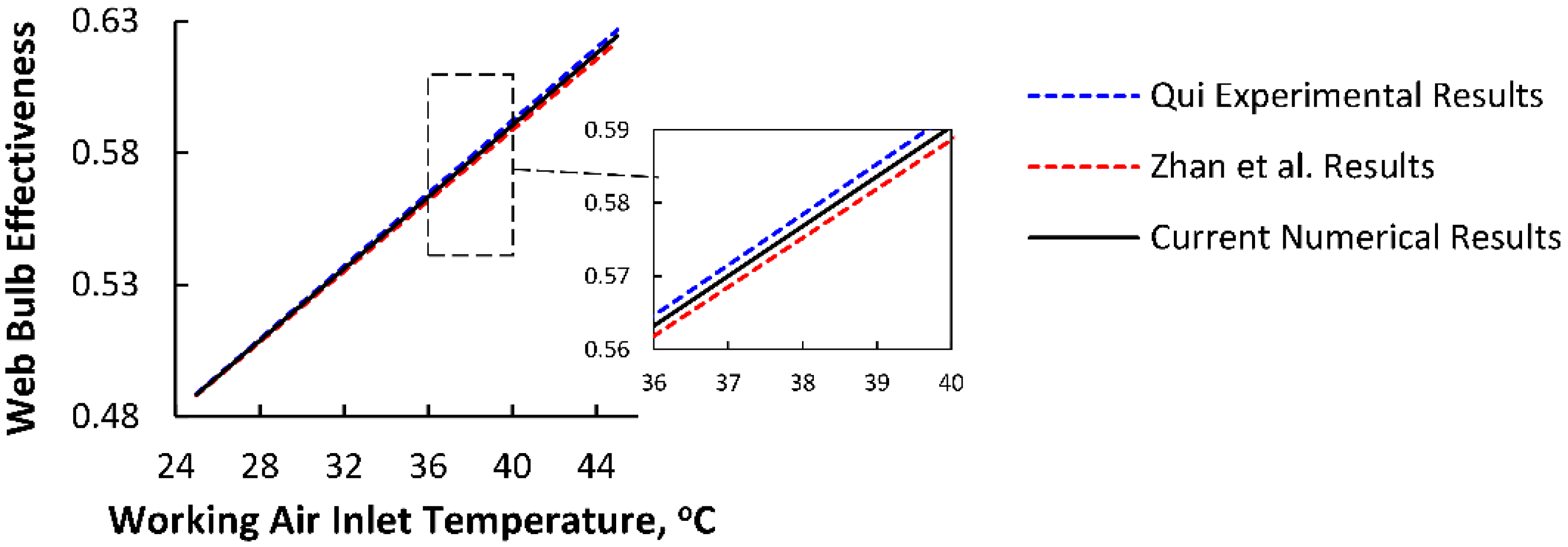
3. Validation of Numerical Approach

Equations (1)–(4) are the main equations which were used to find the temperature and humidity distribution of the fluids. These equations were discretized using a first-order finite difference formulation. The resulting algebraic equations were simulated on MATLAB using appropriate boundary conditions. A convergence study was conducted and the relative error was calculated for the product air outlet temperature using the temperature of previous space–step iteration. A schematic description of the methodology is shown in Figure 3.
The results of this study were validated in two parts, as described in the following sections. However, it must be stressed that both of the configurations analyzed in Section 3.1 and Section 3.2 are cross-flow configurations of the M Cycle.

3.1. Comparison with an M50 Air Cooler [43] (Part I)

In this section, a validation study was conducted comparing the current numerical work with the experimental results [22] of an HMX manufactured by Coolorado Corporation [43]. The operating and geometric conditions for the experimental results of [22] are given in Table 3.
Additionally, the details of the instrumentation utilized in the experimental testing of [22] are shown in Table 4.
All the sensors reported in Table 4 were connected to a CR10X data logger (manufacturer: Campbell Scientific) and a computer recorded the data after every three minutes. Weerts’s [22] experiments were not performed to give the direct trends in the product air or the working air; therefore, a correlation method [27] was used for the validation of the results. Through a few trial calculations, for this case, the convergence criteria is set to be 0.001; therefore, the HMX was divided into 800 elements in the x direction and 860 elements in the y direction, making a grid of 688,000 cells. On this grid, the outlet temperature of the product air, the outlet temperature of the working air, and the outlet absolute humidity of the working air were recorded. The correlation-based validation is shown in Figure 4a–c) for the product air outlet temperature, working air outlet temperature, and working air absolute humidity (respectively).

3.2. Comparison with a TAC-150 [44] (Part II)

In this section, the validation of the results was conducted as a comparison with a TAC-150 air cooler developed by ISAW Corporation Limited [44]. Qui [45] experimentally analyzed the TAC-150 air cooler. The experimental conditions from Qui’s [45] work are presented in Table 5.
The overall dimensions of the HMX used in the TAC-150 cooler are 270 × 290 × 250 mm3, and it has a length of 192 mm for the primary air stream. The lower half of the intake side which has a length of 82 mm contains the dry and wet channels. A further 8 mm length is left towards both halves of the intake air length, thus making a total of 290 mm in length and 7 dry channels. The details of the testing instruments used in the experimentation by Qui [45] are presented in Table 6.
The instrumentation presented in Table 6 was connected to a data-logging system with name code DT500. Further details of the experimentation procedure can be found in [45]. Through a few trial calculations, for this case, the convergence criteria is set to be 0.001; therefore, the HMX was divided into 450 elements in the x direction and 560 elements in the y direction, making a grid of 252,000 cells. The comparison is presented in Figure 5. The level of agreement between these results gives sufficient confidence that the mathematical modeling of the air flow and heat transfer is reliable.

4. Modelling Setup

Simulations for the current analysis were carried out using nanofluid as an evaporation medium after the detailed benchmarking carried out in Section 3. The governing equations (Table 1) were discretized using a first-order finite difference formulation. The convergence criterion was set to 0.001; therefore, a total of 1300 elements in the x direction and 1,456 elements in the y direction were solved, giving 1,892,800 cells. The thermophysical properties of the nanofluid were extracted from Engineering Equation Solver (EES) [46]. Other geometric and operating parameters are presented in Table 7.

5. Results and Discussion

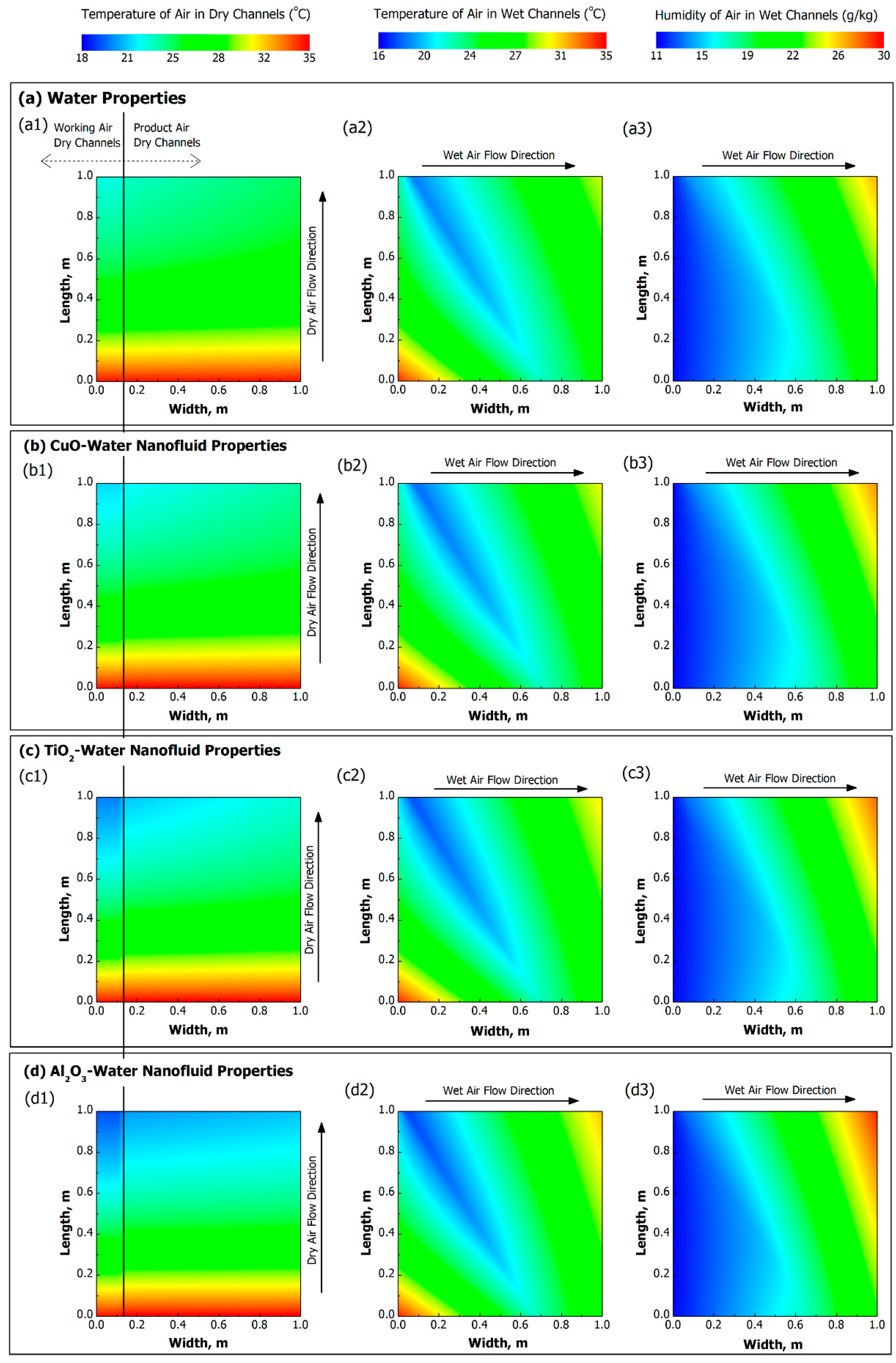
5.1. Heat and Mass Transfer Characteristics of the HMX

The heat and mass transfer characteristics of the HMX are explained in terms of the temperature and humidity distribution for four kinds of evaporation media (water, CuO nanofluid, TiO2 nanofluid, and Al2O3 nanofluid) in dry and wet channels as described in Figure 6a–d.
The working air enters the HMX at 35 °C having a wet bulb temperature of 21.99 °C and a dew point temperature of 15.77 °C. It is observed, generally, that the working air in the dry channel achieves a lower temperature as compared with the product air channels, as described in Figure 6 (a1, b1, c1, d1), because of the flow rate decrement in the dry channel as fluid is diverted towards the wet channel. Furthermore, the air in some initial channels of the product air leaves the HMX at lower temperatures compared with the product air leaving the last channels. A ~7% increment in the temperature of the product air is observed while moving from product air channel 1 to product air channel 33 using water as the evaporation medium; this was also observed by Weerts [22] in their experimental results. Furthermore, it is observed that the average exit temperature of the product air from all channels is 23.9 °C for water, 22.9 °C for CuO nanofluid, ~22 °C for TiO2 nanofluid, and 20.8 °C for Al2O3 nanofluid. This indicates that the original design of the HMX cannot achieve a sub-wet bulb temperature using the parameters mentioned in Table 1. However, the HMX can achieve sub-wet bulb temperature by using either TiO2 or Al2O3 nanofluid as an evaporation medium in the wet channel.
The working air in the dry channel is drawn to the working air wet channels. It can be observed in Figure 6 (a2, b2, c2, d2) that the inlet temperature of the working air in the wet channel is equal to the air temperature leaving the working air–dry channels. Such a behavior of the temperature distribution of the wet air was also reported by Bolotin et al. [47] for a cross-flow HMX. For wet air channel 1 (using water), the working air enters at a temperature of 34.3 °C and attain its wet bulb temperature (21.8 °C) at a channel width ratio of 70%. After this condition (saturation condition), the working air absorbs heat from the adjacent product air channels, causing an elevation in its temperature, and leaves the HMX at ~25 °C. However, as the count of the wet channels increases from 1 to 32, the saturation length is decreased because the working air in wet channel 32 enters at the lowest temperature (i.e., ~22.9 °C). Therefore, we can observe a decrease in saturation length while increasing the count of wet channels for each of Figure 6 (a2, b2, c2, d2). However, one important phenomenon observed here is that the saturation length of the working air also varies under the addition of nanofluids, i.e., the saturation length in wet channel 1 is 69% for the CuO nanofluid, 68% for the TiO2 nanofluid, and 66% for the Al2O3 nanofluid. It is also observed that the exit temperature of the nanofluid-based evaporation media is high compared with that of water because of the enhanced heat and mass characteristics of the nanofluids. The temperature of the working air at the exit of the wet channels using alumina nanofluid is higher than that of the other two types, which signifies the lower product air temperature for alumina-based nanofluid because the working air absorbs more heat in the case of alumina nanoparticles.
The humidity distributions of the working air in the wet channel for all types of evaporation media are shown in Figure 6 (a3, b3, c3, d3). The humidity is increasing with the wet air flow direction because of the constant moisture addition from the evaporation medium. The saturation conditions of the wet air can also be described here, as it can be observed that the starting channels of the wet air need more length to reach saturation; however, the requirement of the saturation length is decreased with the increase in wet channel count. Similarly, it is also observed that the saturation length is decreased by using either CuO-, TiO2-, or Al2O3-based nanofluid. Once the saturation is achieved, the working air only absorbs the amount of moisture that is required to keep it saturated in the wet channel. The average exit humidity of air from all wet channels is ~23.6 g/kg for water, 24.5 g/kg for CuO nanofluid, 25.20 g/kg for TiO2 nanofluid, and ~26.2 g/kg for Al2O3-based nanofluid.
This differences in the temperature and humidity plots of all four kinds of evaporation media are observed because of their differences in thermo-physical properties including thermal conductivity, thermal diffusivity, and heat capacity. These differences in the thermophysical properties correspond to the enhanced heat and mass transfer characteristics of the nanofluids over ordinary water. Since the thermo-physical properties of Al2O3-based nanofluid are significantly higher than those of the other types, the product air temperature is lower at the exit of the dry channels, and the working air temperature and humidity are high at the exit of wet channels as compared to those for other nanofluids.
The differences in heat and mass transfer characteristics among all of these four kinds of evaporation media can also be described in terms of heat flux and water evaporation rate to better understand this behavior. For this purpose, simulations were conducted for the HMX using normal water properties as well as all three types of nanofluids; the results are reported in Figure 7. It can be observed that the heat flux and the water evaporation rate (WER) increase with the increase in inlet temperature. The working air in the wet channel has greater capacity to cause evaporation in the wet channel for high working air inlet temperatures and, as a result, the heat flux of the product air is increased. Similarly, the water evaporation rate is also high for high working air temperatures because air at higher temperature has a greater tendency to cause evaporation. However, the addition of the nanoparticles further enhances the heat flux of the product air [31] and the water evaporation rate [48] in the wet channel. The thermo-physical properties of the nanofluid based on alumina are higher as compared to those of the nanofluids based on copper oxide and titanium oxide; therefore, the heat flux and WER of the alumina-based nanofluid are the highest reported among all. Increases of 24.2% in the heat flux and 22.2% in the water evaporation rate are observed when using alumina nanofluid as compared to water at a temperature of 40 °C.

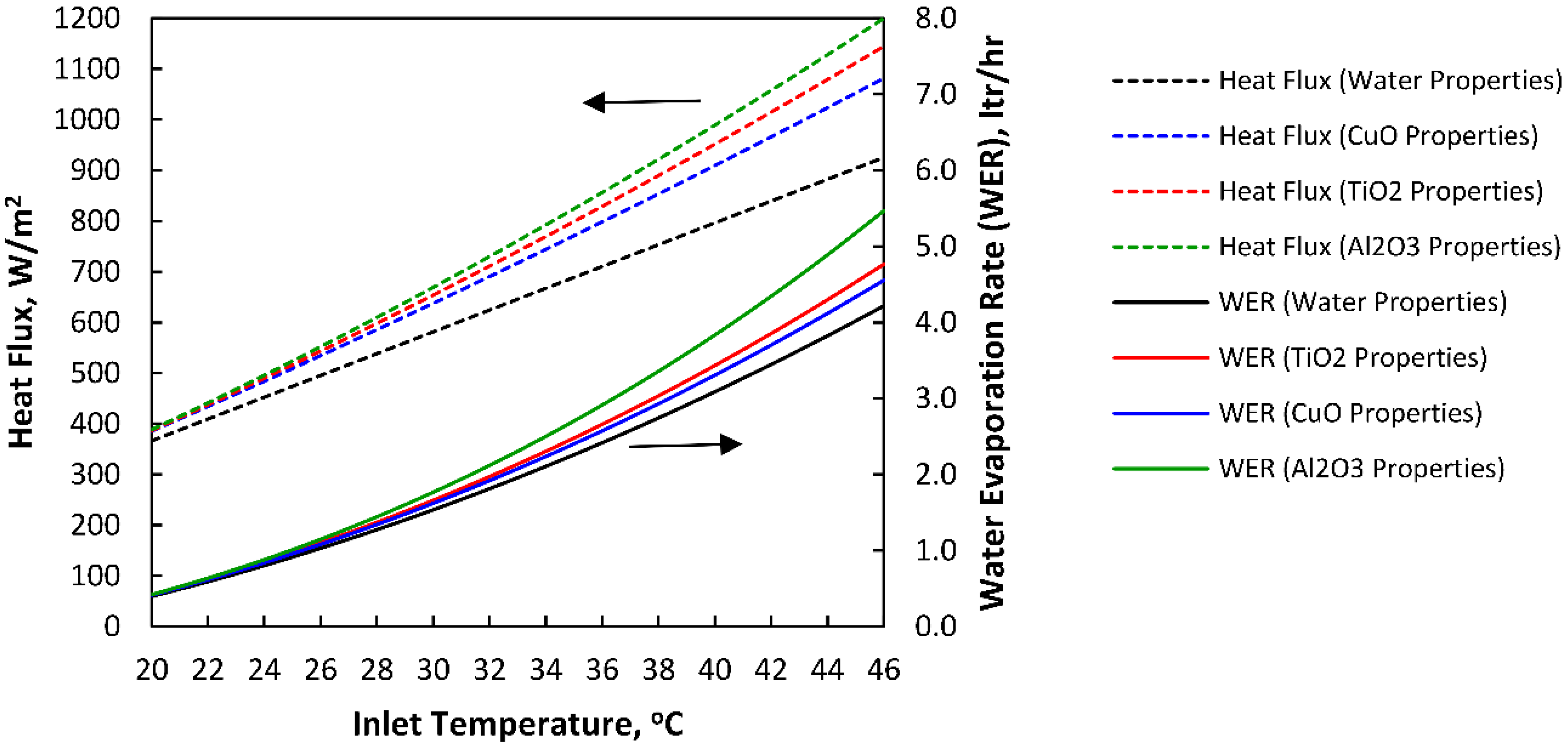
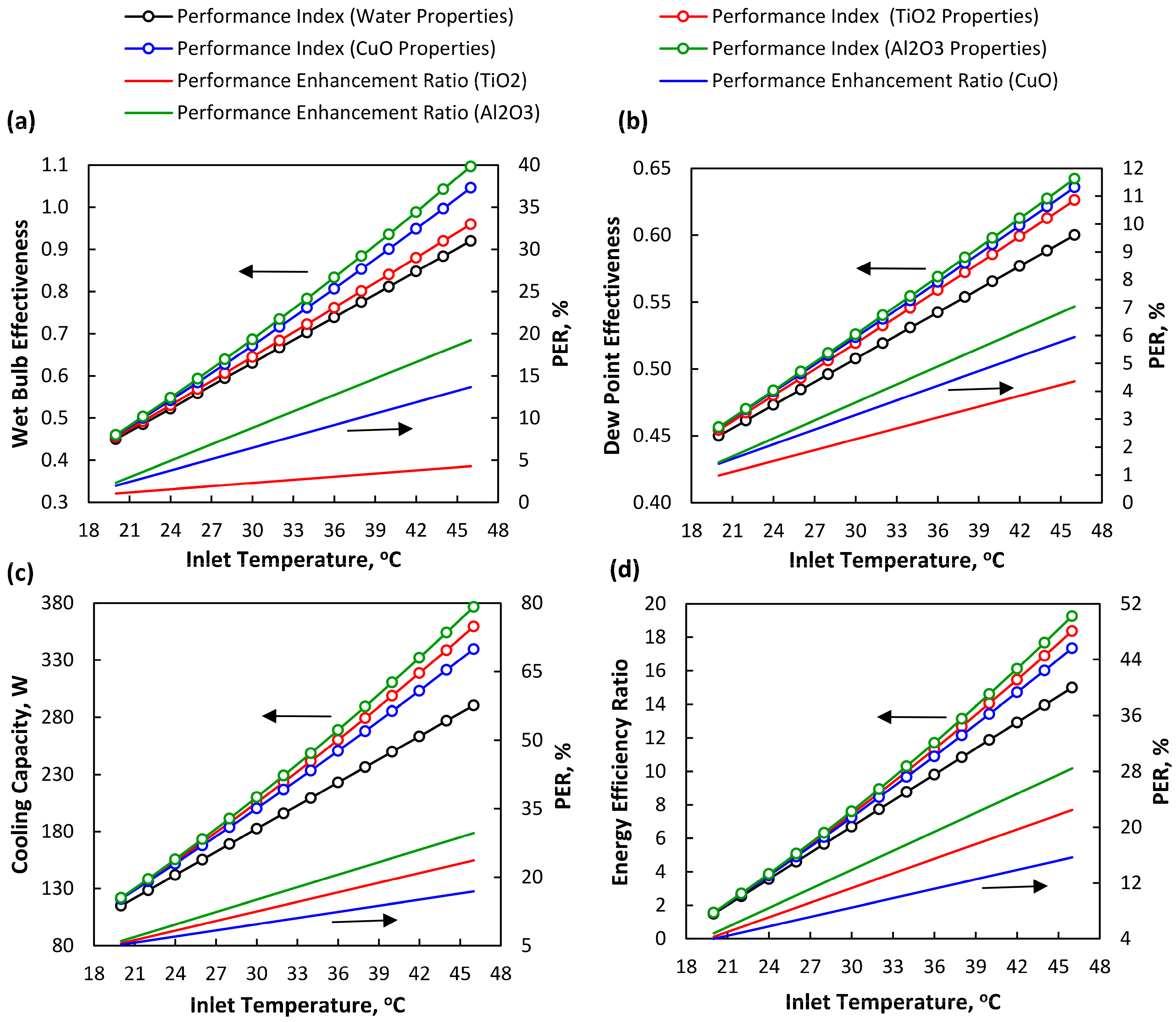
5.2. Performance of HMX Considering Different Types of Nanofluids

Figure 8 shows the influence of the inlet air temperature on the cooling effectiveness, cooling capacity, and energy efficiency ratio of the HMX along with the behavior of each type of nanofluid. It is observed that all performance parameters are increasing with the increase in temperature. This is justified by the conclusion drawn by Jradi et al. [49] that the temperature gradient between water and working air is high for a high range of temperatures of the inlet working air, therefore giving the potential for water evaporation.
One important conclusion that can be drawn from Figure 8a,b is that cooling effectiveness is very sensitive to the addition of nanoparticles to the wet channel. The highest cooling effectiveness is observed for alumina-based nanofluid having a PER ranging from 2.34% to 19.24% for wet bulb effectiveness and 1.14% to 7.04% for dew point effectiveness for a temperature range of 20 °C to 46 °C. The PER for alumina-based nanofluid is high because of its natural higher values of heat capacity, thermal diffusivity, and thermal conductivity as compared to the other two types of nanoparticles (Table 1).
Figure 8c shows the variation of the cooling capacity and Figure 8d shows the energy efficiency ratio with temperature. The behavior of the different types of nanofluid and using water properties is also depicted in these figures. The cooling capacity shows an increasing trend with the increase in inlet air temperature. Anisimov et al. [27] suggested that a higher temperature of working air facilities the water evaporation phenomenon; therefore, it can carry more heat from the product air and, as a result, the cooling capacity increases with air temperature. Since the cooling capacity increases with increase in temperature, the EER also increases for the same blowing power as the mass flow rate remains the same. Furthermore, the addition of nanofluids greatly influences the cooling capacity and EER of the HMX. The PER of alumina-based nanofluid varies from 6.11% to 29.66% for the cooling capacity of the HMX and from 4.77% to 28.43% for the enhancement in energy efficiency ratio.
Results have shown that the alumina-based nanofluid has higher performance in terms of cooling effectiveness, cooling capacity, and energy efficiency ratio as compared to water and other types of nanofluids (CuO- and TiO2-based). The literature [23] has also shown that the alumina-based nanofluid is the most viable option among current trending types of nanofluids because of its ease of availability, cost effectiveness, and preparation method. Therefore, an alumina-based nanofluid is the recommended option to be used in this configuration of a cross-flow HMX as an energy-efficient alternative.

5.3. Parametric Study for Alumina Oxide Nanoparticles in the Wet Channel of the HMX

In this section, a parametric study was conducted specifically related to alumina nanoparticle properties and HMX performance parameters. The alumina oxide nanoparticle shows the highest performance index; therefore, further analysis was only carried out using this nanoparticle.

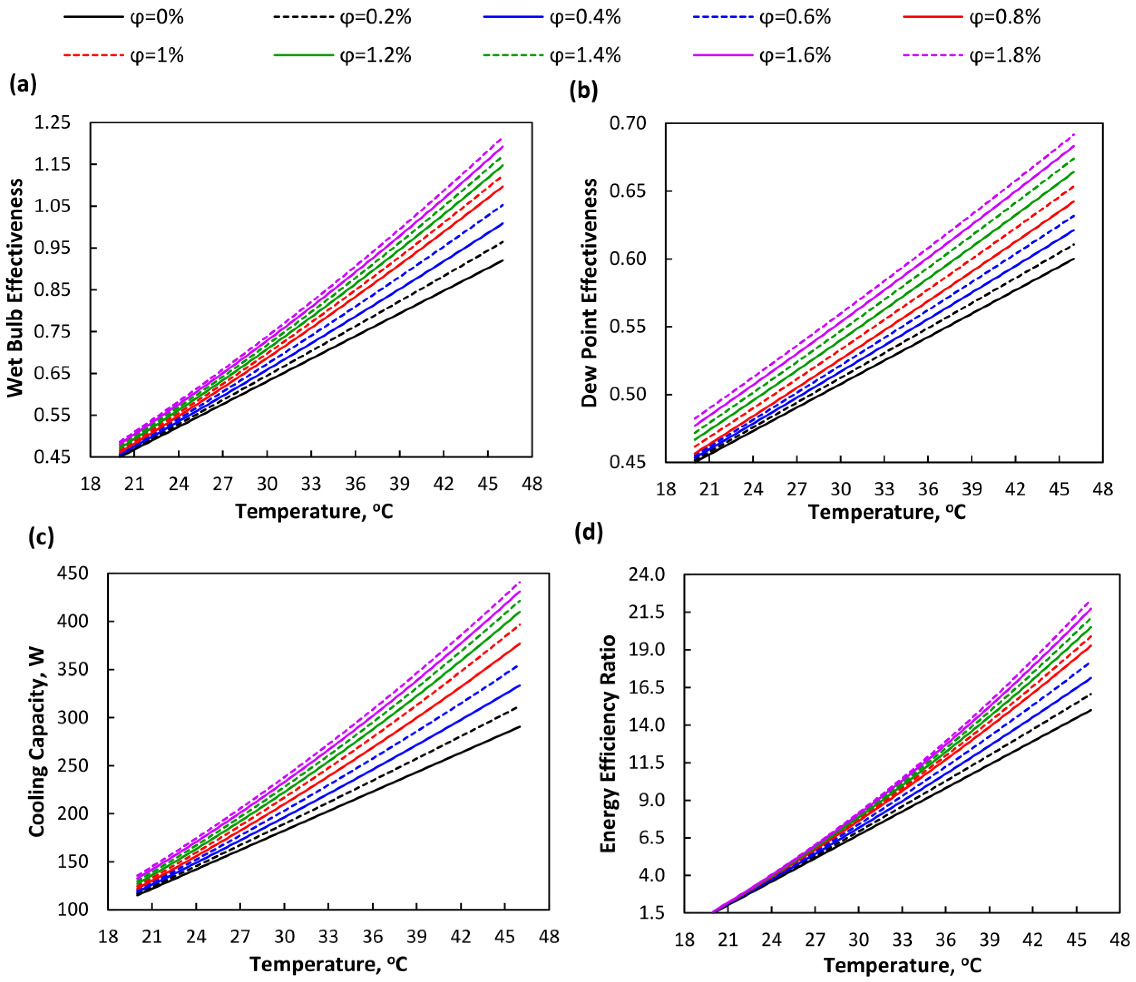
5.3.1. Influence of Particle Volume Fraction on Cooling Performance

Figure 9 shows the influence of particle volume fraction on the performance parameters of the HMX. The simulation was run between temperature and performance parameters for a particle volume fraction ranging between 0.2% and 1.8%. Maheshwary et al. [24] proposed an analysis of the influence of the particle volume fraction on the pumping power. They found that pumping power is insignificant until 1.8% particle volume fraction and shoots up after this volume fraction; therefore, in this study, a maximum particle volume fraction of 1.8% was considered to keep the pumping power consistent by the addition of nanoparticles.
It was observed that the performance parameters (cooling effectiveness, cooling capacity, and EER) are directly proportional to the particle volume fraction. The heat and mass transfer characteristics of the nanofluid are increased with the increment of the particle volume fraction because the density, viscosity, thermal diffusivity, and other parameters are calculated using the particle volume fraction. Furthermore, it is observed that the increment in the performance parameters is small after a particle volume fraction of 1%. Therefore, it is suggested to use a maximum of 1% of alumina-based nanoparticles in the wet channel of the HMX.

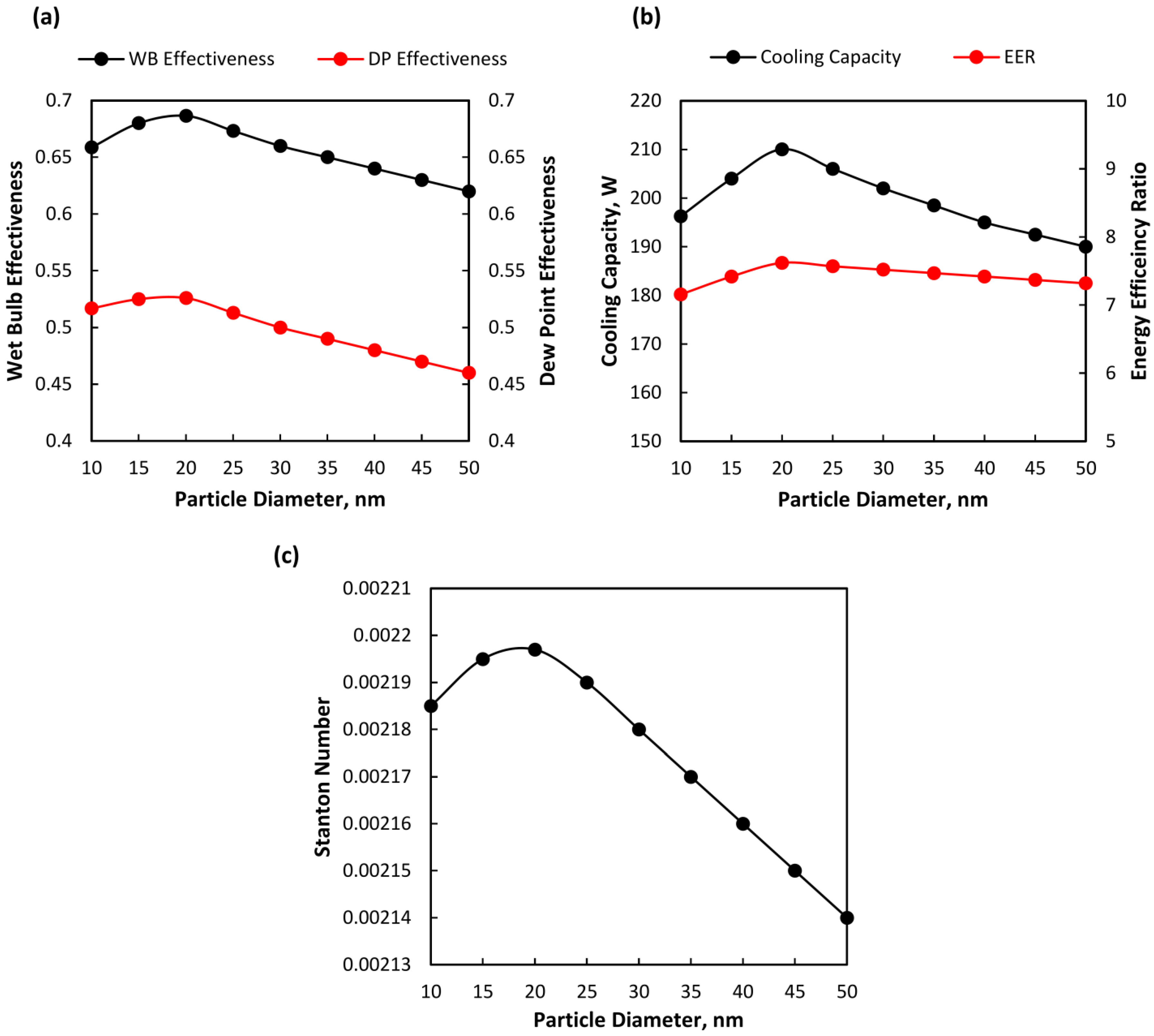
5.3.2. Influence of Particle Diameter on Cooling Performance

The influence of the volume fraction was already noted in Section 5.3.1. However, the role of particle size at a given volume fraction is further analyzed here. For this purpose, the nanoparticle diameter was varied from 10 nm to 50 nm, keeping the other parameters as mentioned in Table 7, and their influence on performance parameters is shown in Figure 10a,b.
It can be noted that the variation in the performance parameters is strongly dependent on particle size. The performance parameters are increasing until a particle diameter of around 20 nm and decrease afterwards. It is not directly apparent as to what causes the variation in performance parameters. Therefore, in order to investigate this behavior, a plot of Stanton numbers is shown in Figure 10c. The Stanton number signifies the influence of a particle as a heat storage unit compared to its convective heat transfer ability. It is quite clear that the Stanton number is also increasing up to a particle size of around 20 nm and decreases afterwards. This suggests a threshold of the Stanton number. For a particle size less than 20 nm, the threshold of the Stanton number is not achieved; therefore, the performance parameters are increasing until the threshold is achieved (dp = 20 nm) because the convective coefficient is increasing due to the increase in the size of the particle. However, for large particle size (dp > 20 nm), the internal storage capacity of the particles increases significantly and reduces the convective heat transfer despite the increase in surface area. The change in the volume and surface area of the nanoparticle is quite detrimental to the cooling performance of the HMX, as suggested by the results.

6. Summary and Conclusions

Cross-flow indirect evaporative coolers are applied in residential and commercial buildings because of their high cooling capacity. Water is used as a refrigerant in such cooling devices, and in this work, the performance of a cross-flow indirect evaporative cooler was enhanced by replacing the water with a nanofluid. For this purpose, analysis was carried out using three different combinations of nanofluids including water–alumina, water–copper oxide, and water–titanium oxide. A mathematical model of the conventional cross-flow indirect evaporative cooler was solved coupled with previously established heat and mass transfer correlations of the nanofluids to evaluate the performance in terms of cooling capacity, cooling effectiveness, and energy efficiency ratio. The following are the key findings of the work:
(1) For an inlet air temperature of 40 °C, the heat fluxes for the Al2O3–water, CuO–water, and TiO2–water nanofluids are 24%, 14%, and 19.5%, respectively; these are more than the heat flux using water as an evaporating medium in the wet channel. Similarly, for an inlet air temperature of 40 °C, the water evaporations rate increased by 24.4%, ~7%, and 11% for Al2O3–water, CuO–water, and TiO2–water nanofluids, respectively—more than for using water as an evaporating medium in the wet channel. Therefore, the Al2O3–water nanofluid combination is the most suitable.
(2) The highest performance was reported using Al2O3–water nanofluid as an evaporating medium in the wet channel. The performance enhancement achieved by utilizing this nanofluid as compared to water was a 2.34% to 19.24% increment in wet bulb effectiveness, 1.14% to 7.04% increment in dew point effectiveness, 6.11% to 29.66% increment in cooling capacity, and 4.77% to 28.43% increment in energy efficiency ratio for a temperature range between 20 °C and 46 °C.
(3) A particle volume concentration of 1% and a particle size diameter of 20nm for the Al2O3–water nanofluid is the recommended option for the cross-flow heat and mass exchanger.

Author Contributions

Conceptualization, L.D. and V.C.; Data curation, C.L. and S.T.; Formal analysis, C.L. and S.T.; Methodology, C.L.; Project administration, L.D.; Software, C.L.; Writing—original draft, C.L.

Funding

This research received no external funding.

Acknowledgments

The authors are thankful to the kind reviewers for helping us in the improvement of this manuscript.

Conflicts of Interest

The authors declare no conflict of interest.

Nomenclature

A Heat Transfer Surface Area, m2
a Height, m
b Width, m
c p Specific Heat of Fluid, J/(kg·K)
D h Hydraulic Diameter, m
d Molecule Diameter, m
H Enthalpy, kJ/kg
h Convective Heat Transfer Coefficient, W/(m2·K)
h m Convective Mass Transfer Coefficient, (kg·m2)/s
i v Latent Heat of Evaporation, kJ/kg
k f Thermal Conductivity, W/(m·K)
L Length of Channel, m
m Mass Flow Rate of Fluid, kg/s
Nu Nusselt Number
Pe Peclet Number
PER Performance Enhancement Ratio, %
PI Performance Index
Pr Prandtl Number
Q Rate of Heat, W
Re Reynolds Number
Sc Schmidt Number
Sh Sherwood Number
T Temperature, °C
v Velocity of the Fluid, m/s
V B R Particle Brownian Velocity, m/s
Greek Letters
α Thermal Diffusivity, m2/s
D Mass Diffusivity, m2/s
ε Effectiveness
μ Dynamic Viscosity, (N·s)/m2
ω Absolute Humidity, kg/kg
ρ Density, kg/m3
ψ Cooling Capacity, W
ϕ Volume Fraction of Nanofluid
λ w Mean Free Path of Fluid Molecules, nm
Subscripts
D B Dry Bulb
D P Dew Point
dry Dry Channel
Exp Experimental
in Inlet
m Related to Mass Transfer
nf Related to Nanofluid
out Outlet
p Nanoparticle
pa Product Air
s Saturated
w Water
wa Working Air
W B Wet Bulb
wet Wet Channel

References

  1. Emdadi, Z.; Asim, N.; Yarmo, M.A.; Shamsudin, R.; Mohammad, M.; Sopian, K. Green material prospects for passive evaporative cooling systems: Geopolymers. Energies 2016, 9. [Google Scholar] [CrossRef]
  2. Martínez, P.J.; Llorca, C.; Pla, J.A.; Marténez, P. Experimental validation of the simulation model of a DOAS equipped with a desiccant wheel and a vapor compression refrigeration system. Energies 2017, 10, 1330. [Google Scholar] [CrossRef]
  3. Ma, Y.; Saha, S.C.; Miller, W.; Guan, L. Parametric analysis of design parameter effects on the performance of a solar desiccant evaporative cooling system in brisbane, Australia. Energies 2017, 10, 849. [Google Scholar] [CrossRef]
  4. Tariq, R.; Sheikh, N.A.; Xamán, J.; Bassam, A. An innovative air saturator for humidification-dehumidification desalination application. Appl. Energy 2018, 228, 789–807. [Google Scholar] [CrossRef]
  5. Tariq, R.; Sheikh, N.A. Numerical heat transfer analysis of Maisotsenko Humid Air Bottoming Cycle—A study towards the optimization of the air-water mixture at bottoming turbine inlet. Appl. Therm. Eng. 2018, 133, 49–60. [Google Scholar] [CrossRef]
  6. Noroozi, A.; Veneris, Y.S. Thermal Assessment of a Novel Combine Evaporative Cooling Wind Catcher. Energies 2018, 11, 442. [Google Scholar] [CrossRef]
  7. Li, S.; Jeong, J.-W. Energy Performance of Liquid Desiccant and Evaporative Cooling-Assisted 100% Outdoor Air Systems under Various Climatic Conditions. Energies 2018, 11, 1377. [Google Scholar] [CrossRef]
  8. Boukhanouf, R.; Alharbi, A.; Ibrahim, H.G.; Amer, O.; Worall, M. Computer modelling and experimental investigation of building integrated sub-wet bulb temperature evaporative cooling system. Appl. Therm. Eng. 2017, 115, 201–211. [Google Scholar] [CrossRef] [Green Version]
  9. Lin, J.; Wang, R.Z.; Kumja, M.; Bui, T.D.; Chua, K.J. Modelling and experimental investigation of the cross-flow dew point evaporative cooler with and without dehumidification. Appl. Therm. Eng. 2017, 121, 1–13. [Google Scholar] [CrossRef]
  10. Fakhrabadi, F.; Kowsary, F. Optimal design of a regenerative heat and mass exchanger for indirect evaporative cooling. Appl. Therm. Eng. 2016, 102, 1384–1394. [Google Scholar] [CrossRef]
  11. Tariq, R.; Zhan, C.; Zhao, X.; Sheikh, N.A. Numerical study of a regenerative counter flow evaporative cooler using alumina nanoparticles in wet channel. Energy Build. 2018, 169, 430–443. [Google Scholar] [CrossRef]
  12. Pandelidis, D.; Anisimov, S.; Rajski, K.; Brychcy, E.; Sidorczyk, M. Performance comparison of the advanced indirect evaporative air coolers. Energy 2017, 135, 138–152. [Google Scholar] [CrossRef]
  13. Khalid, O.; Ali, M.; Sheikh, N.A.; Ali, H.M.; Shehryar, M. Experimental analysis of an improved Maisotsenko cycle design under low velocity conditions. Appl. Therm. Eng. 2016, 95, 288–295. [Google Scholar] [CrossRef]
  14. Zhan, C.; Zhao, X.; Smith, S.; Riffat, S.B. Numerical study of a M-cycle cross-flow heat exchanger for indirect evaporative cooling. Build. Environ. 2011, 46, 657–668. [Google Scholar] [CrossRef]
  15. Zhan, C.; Duan, Z.; Zhao, X.; Smith, S.; Jin, H.; Riffat, S. Comparative study of the performance of the M-cycle counter-flow and cross-flow heat exchangers for indirect evaporative cooling - Paving the path toward sustainable cooling of buildings. Energy 2011, 36, 6790–6805. [Google Scholar] [CrossRef]
  16. Anisimov, S.; Pandelidis, D.; Danielewicz, J. Numerical analysis of selected evaporative exchangers with the Maisotsenko cycle. Energy Convers. Manag. 2014, 88, 426–441. [Google Scholar] [CrossRef]
  17. Pandelidis, D.; Anisimov, S.; Drag, P. Performance comparison between selected evaporative air coolers. Energies 2017, 10. [Google Scholar] [CrossRef]
  18. Xu, P.; Ma, X.; Zhao, X.; Fancey, K.S. Experimental investigation on performance of fabrics for indirect evaporative cooling applications. Build. Environ. 2016, 110, 104–114. [Google Scholar] [CrossRef]
  19. Duan, Z.; Zhao, X.; Li, J. Design, fabrication and performance evaluation of a compact regenerative evaporative cooler: Towards low energy cooling for buildings. Energy 2017, 140, 506–519. [Google Scholar] [CrossRef]
  20. Xu, P.; Ma, X.; Zhao, X.; Fancey, K. Experimental investigation of a super performance dew point air cooler. Appl. Energy 2017, 203, 761–777. [Google Scholar]
  21. Lee, J.; Lee, D.Y. Experimental study of a counter flow regenerative evaporative cooler with finned channels. Int. J. Heat Mass Transf. 2013, 65, 173–179. [Google Scholar] [CrossRef]
  22. Weerts, B.A. NSIDC Green Data Center Project: Coolerado and Modeling an Application of the Maisotsenko Cycle. Master’s Thesis, University of Colorado, Boulder, CO, USA, 2012. [Google Scholar]
  23. Pinto, R.V.; Fiorelli, F.A.S. Review of the mechanisms responsible for heat transfer enhancement using nanofluids. Appl. Therm. Eng. 2016, 108, 720–739. [Google Scholar] [CrossRef]
  24. Maheshwary, P.B.; Handa, C.C.; Nemade, K.R. A comprehensive study of effect of concentration, particle size and particle shape on thermal conductivity of titania/water based nanofluid. Appl. Therm. Eng. 2017, 199, 79–88. [Google Scholar] [CrossRef]
  25. Albadr, J.; Tayal, S.; Alasadi, M. Case Studies in Thermal Engineering Heat transfer through heat exchanger using Al 2 O 3 nanofluid at different concentrations. Case Stud. Therm. Eng. 2013, 1, 38–44. [Google Scholar] [CrossRef]
  26. Colangelo, G.; Favale, E.; Milanese, M.; de Risi, A.; Laforgia, D. Cooling of electronic devices: Nanofluids contribution. Appl. Therm. Eng. 2017, 127, 421–435. [Google Scholar] [CrossRef]
  27. Anisimov, S.; Pandelidis, D. Numerical study of the Maisotsenko cycle heat and mass exchanger. Int. J. Heat Mass Transf. 2014, 75, 75–96. [Google Scholar] [CrossRef]
  28. Kakaç, S.; Pramuanjaroenkij, A. Single-phase and two-phase treatments of convective heat transfer enhancement with nanofluids—A state-of-the-art review. Int. J. Therm. Sci. 2016, 100, 75–97. [Google Scholar] [CrossRef]
  29. Vanaki, S.M.; Ganesan, P.; Mohammed, H.A. Numerical study of convective heat transfer of nanofluids: A review. Renew. Sustain. Energy Rev. 2016, 54, 1212–1239. [Google Scholar] [CrossRef]
  30. Beck, M.P.; Yuan, Y.; Warrier, P.; Teja, A.S. The effect of particle size on the thermal conductivity of alumina nanofluids. J. Nanopart. Res. 2009, 11, 1129–1136. [Google Scholar] [CrossRef]
  31. Chiam, H.W.; Azmi, W.H.; Adam, N.M.; Ari, M.K.A.M. Numerical study of nanofluid heat transfer for different tube geometries—A comprehensive review on performance. Int. Commun. Heat Mass Trans. 2017, 86, 60–70. [Google Scholar] [CrossRef]
  32. Godson, L.; Raja, B.; Lal, D.M.; Wongwises, S. Enhancement of heat transfer using nanofluids—An overview. Renew. Sustain. Energy Rev. 2010, 14, 629–641. [Google Scholar] [CrossRef]
  33. Sieder, E.N.; Tate, G.E. Heat Transfer and Pressure Drop of Liquids in Tubes. Ind. Eng. Chem. 1936, 28, 1429–1435. [Google Scholar] [CrossRef]
  34. Singh, P.; Kumar, M. Mass transfer in MHD flow of alumina water nanofluid over a flat plate under slip conditions. Alexandria Eng. J. 2015, 54, 383–387. [Google Scholar] [CrossRef]
  35. Cussler, E.L. Diffusion: Mass Transfer in Fluid Systems; Cambridge University Press: Cambridge, UK, 1997. [Google Scholar]
  36. Welty, J.; Wicks, C.; Wilson, R.; Rorrer, G. Fundamentals of Momentum, heat, and Mass Transfer; John Wiley and Sons: Hoboken, NJ, USA, 2008. [Google Scholar]
  37. Yang, L.; Xu, J.; Du, K.; Zhang, X. Recent developments on viscosity and thermal conductivity of nanofluids. Powder Technol. 2017, 317, 348–369. [Google Scholar] [CrossRef]
  38. Xuan, Y.; Roetzel, W. Conceptions for heat transfer correlation of nanofluids. Int. J. Heat Mass Transf. 2000, 43, 3701–3707. [Google Scholar] [CrossRef]
  39. Li, Q.; Xuan, Y. Convective heat transfer and flow characteristics of Cu-water nanofluid. Sci. China Ser. E Technol. Sci. 2002, 45, 408–416. [Google Scholar]
  40. Chon, C.H.; Kihm, K.D.; Lee, S.P.; Choi, S.U.S. Empirical correlation finding the role of temperature and particle size for nanofluid (Al2O3) thermal conductivity enhancement. Appl. Phys. Lett. 2005, 87. [Google Scholar] [CrossRef]
  41. Incropera, F.P.; DeWitt, D.P.; Bergman, T.L.; Lavine, A.S. Fundamentals of Heat and Mass Transfer; John Wiley & Sons: Hoboken, NJ, USA, 2007. [Google Scholar]
  42. Pandelidis, D.; Anisimov, S.; Worek, W.M. Comparison study of the counter-flow regenerative evaporative heat exchangers with numerical methods. Appl. Therm. Eng. 2015, 84, 211–224. [Google Scholar] [CrossRef]
  43. Maisotsenko, V.E.; Gillan, L.; Heaton, T.L.; Gillan, A.D. Method and Plate Apparatus for Dew Point Evaporative Cooler. U.S. Patent 09,966,928, 27 September 2001. [Google Scholar]
  44. Catalogue Data of the Fiber Heat and Mass Exchanger (Natural Air Conditioner); ISAW Corporation Limited: Hangzhou, China, 2005.
  45. Qiu, G. A Novel Evaporative/Desiccant Cooling System. Ph.D. Thesis, University of Nottingham, Nottingham, UK, 2007. [Google Scholar]
  46. EES: Engineering Equation Solver|F-Chart Software: Engineering Software. Available online: http://www.fchart.com/ees/ (accessed on 28 September 2018).
  47. Bolotin, S.; Vager, B.; Vasilijev, V. Comparative analysis of the cross-flow indirect evaporative air coolers. Int. J. Heat Mass Transf. 2015, 88, 224–235. [Google Scholar] [CrossRef]
  48. Ashrafmansouri, S.S.; Nasr Esfahany, M. Mass transfer in nanofluids: A review. Int. J. Therm. Sci. 2014, 82, 84–90. [Google Scholar] [CrossRef]
  49. Jradi, M.; Riffat, S. Experimental and numerical investigation of a dew-point cooling system for thermal comfort in buildings. Appl. Energy 2014, 132, 524–535. [Google Scholar] [CrossRef]
Figure 1. Schematic of the cross-flow heat and mass exchanger.
Energies 11 02656 g001
Figure 2. Control volume selected for development of the mathematical model, showing product air channel and working air wet channel.
Energies 11 02656 g002
Figure 3. Methodology diagram of the numerical approach.
Energies 11 02656 g003
Figure 4. Correlation-based validation with Weerts’s data [22] for (a) product air outlet temperature; (b) working air outlet temperature; and (c) working air outlet absolute humidity.
Energies 11 02656 g004
Figure 5. Validation of results (Part II): comparison of numerical results with the experiment results from Qui [45] and numerical results from Zhan et al. [14] for RH = 35%, dry bulb temperature of working air = 25 °C to 45 °C, and volume flow rate = 130 m3/h.
Energies 11 02656 g005
Figure 6. (a1a3) Temperature distribution of product air and working air and humidity distribution of working air, respectively, using water properties. (b1b3) Temperature distribution of product air and working air and humidity distribution of working air, respectively, using CuO–water nanofluid properties. (c1c3) Temperature distribution of product air and working air and humidity distribution of working air, respectively, using TiO2–water nanofluid properties. (d1d3) Temperature distribution of product air and working air and humidity distribution of working air, respectively, using Al2O3–water nanofluid properties.
Energies 11 02656 g006
Figure 7. Influence of nanofluids on heat flux and water evaporation rate.
Energies 11 02656 g007
Figure 8. Influence of inlet temperature on (a) wet bulb effectiveness; (b) dew point effectiveness; (c) cooling capacity; and (d) energy efficiency ratio, with and without using nanofluids.
Energies 11 02656 g008
Figure 9. Influence of nanoparticle volume fraction on (a) wet bulb effectiveness; (b) dew point effectiveness; (c) cooling capacity; and (d) energy efficiency ratio.
Energies 11 02656 g009
Figure 10. Influence of particle diameter on (a) wet bulb (WB), dew point (DP) cooling effectiveness; (b) cooling capacity, Energy Efficiency Ratio (EER); and (c) Stanton number.
Energies 11 02656 g010
Table 1. Energy and mass balance laws applied to different channels of the heat and mass exchanger (HMX).
ParameterEquation
Energy Balance
Product Air Channel (Temperature Distribution) T pa dry x = h pa dry × y m pa dry c p pa dry ( T pa dry T wa wet ) (1)
Working Air Dry Channel (Temperature Distribution) T wa dry x = h wa dry × y m wa dry c p wa dry ( T wa dry T wa wet ) (2)
Working Air Wet Channel
(Temperature Distribution)
T wa wet y = x m wa wet c p wa wet [ h wa wet ( T wa dry T wa wet ) + h m wa wet i v ( ω s wet ω wa wet ) + h nf ( T wa wet T nf ) ] (3)
Mass Balance Equation:
Working Air Wet Channel
(Humidity Distribution)
ω wa wet y = h m wa wet × x m wa wet ( ω s wet ω wa wet ) (4)
Table 2. Details of the calculation of the heat and mass transfer parameters of the fluids.
ParameterEquation
Product Air and Working Air Dry Channel
Hydraulic Diameter D h pa dry = D h wa dry = 4 ( b × a ) ( 2 a + 2 b ) (5)
Reynolds Number Re pa dry = Re wa dry = ρ wa vD h wa dry μ wa (6)
Nusselt Number [33] Nu pa dry = Nu wa dry = 1.86 ( Re wa dry × Pr wa L / D h wa dry ) 1 3 ( μ wa μ s wa ) 0.14 (7)
Convective Heat Transfer Coefficient h pa dry = h wa dry = Nu wa dry × k wa dry D h wa dry (8)
Working Air Wet Channel
Hydraulic Diameter D h wa wet = 4 ( a × L ) ( 2 L + 2 a ) (9)
Reynolds Number Re wa wet = ρ wa vD h wa wet μ wa (10)
Nusselt Number [33] Nu wa wet = 1.86 ( Re wa wet × Pr wa L / D h wa wet ) 1 3 ( μ wa μ s wa ) 0.14 (11)
Convective Heat Transfer Coefficient h wa wet = Nu wa wet × k wa wet D h wa wet (12)
Mass Diffusivity of Nanofluid [34] D nf = ( 1 ϕ ) ) D w (13)
Mass Diffusivity of Nanofluid and Air [35] D wa nf = 21.2 × 10 6 [ 1 + ( 0.0071 × T wa wet ) ] (14)
Schmidt Number S c wa nf = μ wa D wa nf (15)
Sherwood Number [36] S h = 0.023 Re wa wet 0.83 S c wa nf 1 / 3 (16)
Convective Mass Transfer Coefficient h m wa wet = Sh × k wa wet D h wa wet (17)
Nanofluid Properties
Thermal Conductivity [37] k nf = k w k p + 2 k w + 2 ϕ ( k p k w ) k p + 2 k w ϕ ( k p k w ) (18)
Specific Heat [38] c p nf = ϕ c p p + ( 1 ϕ ) c p w (19)
Density [38] ρ nf = ϕ ρ p + ( 1 ϕ ) ρ w (20)
Thermal Diffusivity [39] α nf = k nf ( 1 ϕ ) ( ρ w c p w ) + ϕ ( ρ p c p p ) (21)
Viscosity [31] μ nf = μ w [ 1 34.87 ( d p d w ) 0.3 ϕ 1.03 ] 1 Range : [ 0.2 % ϕ 9 % 10 nm d p 150 nm 294 K T 324 K ] (22)
Prandtl Number of Nanofluid Pr nf = c p nf × μ nf k nf (23)
Brownian Motion [40] V B R = κ B T w 3 π μ nf d p λ w (24)
Reynolds Number Re p = ρ w V B R d p μ w (25)
Peclet Number [41] P e p = v × d p α nf (26)
Nusselt Number (Laminar) [32] N u nf = 0.4328 ( 1.0 + 11.285 ϕ 0.754 P e p 0.218 ) Re p 0.333 Pr nf 0.4 (27)
Convective Heat Transfer Coefficient h nf = N u nf × k nf D h wa wet (28)
Table 3. Operating and geometric parameters for the experimental results of [22].
No.ParametersQuantityUnits
1Intake air flow rate1095 to 4050m3/h
2Supply-to-working air flow rate ratio1:1-
3Inlet air temperature17.3 to 32.3°C
4Inlet relative humidity7.4 to 62.9%
5Number of product air channels39-
6Product air channel height3.81mm
7Working air channel height2.54mm
8Channel width23.4mm
Table 4. Details of instrumentation for the experimental testing in [22].
No.InstrumentUsageAccuracyManufacturer
1HMP45C temperature sensorTo measure the temperature of working air and product air.0.05 °CCampbell Scientific
2HMP45C humidity sensorTo measure the relative humidity of working air and product air.2%Campbell Scientific
3ZW-007 temperature sensor To measure the inlet air temperature. 0.21 °CHOBO
4ZW-007 humidity sensor To measure the inlet air relative humidity. 2.5%HOBO
5407123 hot wire anemometersTo measure the velocity profile of the air flow.3.0%Extech Instruments
6Fieldpiece HS26 stick meter with thermocouple ATH4 accessory headTo measure the temperature of the HMX filling surface.1 °CFieldpiece
Table 5. Operating and geometric parameters for the experimental results from Qui [45].
No.ParametersQuantityUnits
1Relative humidity of inlet air50%
2Dry bulb temperature of inlet air25–45°C
3Overall dimensions270 × 290 × 250mm3
4Length of primary air section192mm
5Number of dry channels7-
Table 6. Details of instrumentation for the experimental testing by Qui [45].
No.InstrumentUsageAccuracyManufacturer
1HMP45A hygrometer sensorTo measure the temperature of air flow. Operating range: −40 °C to +50 °C
Storage temperature range: −40 °C to +80 °C
Settling time: 500 ms
Vaisala
2HMP45A hygrometer sensorTo measure the relative humidity of air flow. Operating range: 0.8% to 100%
Accuracy: (1) ±2% RH for 0–90% of range.
(2) ±3% RH for 90–100% of range.
Vaisala
Table 7. Input parameters for the simulation.
No.ParametersQuantityUnits
1Working Air Inlet DB Temperature35°C
2Working Air Inlet Absolute Humidity11.2g/kg
3Total Flow Rate of Inlet Air228m3/h
4Product Air Flow Rate150m3/h
5Working Air Flow Rate78m3/h
6Particle Volume Fraction0.8%
7Diameter of Nanoparticles20nm
8Length of Dry Channels1m
9Length of Wet Channels1m
10Width of Channels314mm
11Height of Channels5mm
12Working Air Dry Channels33-
13Product Air Dry Channels5-
14Working Air Wet Channels32-

