Article

Multifield Calculation and Analysis of Excitation Winding Interturn Short Circuit Fault in Turbo-Generator

1
State Key Laboratory of Alternate Electrical Power System with Renewable Energy Sources, North China Electric Power University, Baoding 071003, Hebei, China
2
State Grid Baoding Power Supply Conmpany, Baoding 071051, Hebei, China
*
Author to whom correspondence should be addressed.
Energies 2018, 11(10), 2626; https://doi.org/10.3390/en11102626
Submission received: 7 September 2018 / Revised: 26 September 2018 / Accepted: 28 September 2018 / Published: 1 October 2018
(This article belongs to the Section I: Energy Fundamentals and Conversion)

Abstract

:
Excitation winding interturn short circuit (EWISC) is a common fault in turbo-generators. Once the fault occurs, if not handled in time, it will result in significant security risks to the power system. Using the multifield characteristics of fault generators for a comprehensive diagnosis can make the diagnostic results more accurate and credible. In this paper, taking a TA-1100-78 type, two pole pairs turbo-generator as the research object, the two-dimensional finite element electromagnetic model of stator/rotor and the three-dimensional finite element heat transfer model of rotor were established. The electromagnetic field, temperature field, and stress field of the generator were simulated and analyzed. At the same time, the air gap magnetic field, three-dimensional temperature field, and stress field distribution of the rotor were calculated for EWISC faults in different fault degrees and positions. The results showed that the EWISC fault weakened the air gap magnetic field and caused unbalanced electromagnetic distribution. At the same time, it caused a distortion of the rotor temperature field, resulting in an unbalanced distribution of the temperature field. The stress field was affected by the distortion of temperature field, and the local thermal stress increased but did not exceed the yield limit of the material. Restorable elastic deformation occurred when the rotor was heated, which caused the thermal bending of the rotor. The method adopted in this paper can provide a reference for the calculation of multiphysical field after a generator fault. It is also pointed out that the thermal unbalance influence should not be neglected in the study of generator vibration characteristics.

1. Introduction

With the rapid economic development, demand for electric energy is increasing day by day, and the installed capacity is increasing year by year. At present, the world energy structure is still dominated by thermal power generation, and the installed capacity of nuclear power is also expanding. As the core of thermal power generation and nuclear power generation, the safe and stable operation of turbo-generators is very important to the power grid. However, many internal faults can seriously affect the safe and stable operation of these generators [1,2,3,4,5,6,7]. The rotor of the generator is in high-speed rotating state for a long time, the excitation winding is embedded in the rotor groove and rotates with the rotor, and the interturn insulation is easily destroyed by centrifugal force, which causes excitation winding interturn short circuit (EWISC) faults.
In the past 20 years, scholars all over the world have carried out continuous research on EWISC, mostly focusing on the circuit and electromagnetic characteristics. Reference [8] analyzes the electrical characteristics of EWISC and points out that EWISC faults make the excitation current relatively increased and the reactive power relatively reduced. This method has been applied to some static excitation generators. References [9,10] analyze the variation characteristics of shaft voltage and end leakage flux after generators suffer a EWISC fault, respectively, and points out that EWISC will cause even or fractional harmonic components of generator shaft voltage or end leakage flux. Although the shaft voltage method has been applied in practice somewhere [11], due to the difficulty of measuring the two signals, the actual effect needs to be verified. Reference [12] studies the variation characteristics of electromagnetic power before and after a EWISC fault. This method establishes the functional relationship between electromagnetic power and excitation current and obtains the expected electromagnetic power at any time. Once the actual value of the electromagnetic power deviates from the calculated value, the EWISC fault in the generator can be judged. Reference [13] studies the EWISC fault characteristics transfer law from stator winding, field winding, and exciter armature winding successively to exciter field winding. When the EWISC occurs in the generator, the excitation winding of the exciter generates the nrM/60 times harmonic current. References [14,15] study the amplitude and frequency characteristics of rotor unbalanced magnetic pull of a multipole synchronous generator with EWISC fault. It provides a theoretical basis for diagnosing EWISC fault using vibration response characteristics. Reference [16] studies the influence of EWISC on electromagnetic torque of generator. The calculation and analysis results indicate that EWISC generates AC pulsation components, with their harmonics closely linked to the stator winding configuration. It deepens the fault mechanism of EWISC and lays a foundation for fault monitoring based on mechanical characteristics. References [17,18,19] use different detection coils to monitor variations in the main magnetic field of the generator. The distorted air gap magnetic field will induce even or fractional characteristic harmonics voltage in the detection coil. The detection coil method is the most widely used method at present. Reference [20] presents an on-line fault identification method based on Volterra kernel identification. This method uses the stator branch voltage and stator unbalance branch current as input and output signals of the series model, respectively. When the generator suffers a EWISC fault, the Volterra kernel changes accordingly. In summary, researchers have at present paid attention to the electrical and electromagnetic characteristics of the EWISC. However, the generator is a coupling entity of mechanical, electrical, magnetic, thermal, and other physical quantities. The physical quantities interact with each other, and a EWISC fault is reflected in the generator’s magnetic field, temperature field, stress field, and other aspects.
Although the temperature and stress fields after EWISC have not been reported, in recent years, there has been frequent research on temperature field, stress field, and postfault temperature characteristics of large-scale electrical equipments. Temperature characteristics have received growing attention in the design, monitoring, operation, and maintenance of electrical equipment. Reference [21] systematically collates and synthetically compares various methods of motor temperature calculation, which provides a theoretical basis for applying temperature characteristics to generator state detection and fault diagnosis. In reference [22], a two-dimensional mathematical model and boundary conditions are established to simulate the heat transfer and turbulent flow in the rotor body and ventilation duct. The temperature distribution of the rotor is obtained using the finite volume method based on the computational fluid dynamics principle. Reference [23] gives the heat conduction equation and the corresponding functional equation in the rotor solution domain and uses the finite element method (FEM) to calculate the temperature field when the rotor auxiliary groove and radial ventilation groove are distributed along the rotor axis with variable cross section and variable step size. Reference [24] establishes a coupled model for calculating the three-dimensional fluid-temperature field of rotors with or without deformation of the rotor yoke ventilation duct structure. The finite volume method is used to calculate and analyze the ventilation and heat dissipation of all air-cooled hydro generators. Reference [25] analyzes the temperature field distribution of turbo-generator stator cooling water blocking, which provides a theoretical basis for the diagnosis of stator water blocking faults. Reference [26] calculates and analyzes the stator three-dimensional temperature field of large synchronous generator with broken strands and explores the variation trend of stator temperature distribution under different broken strands. Reference [27] uses FEM to calculate the 3D transient electromagnetic field in the turbo-generator end and the eddy current losses of the end parts. The influence of the changed end ventilation structures on the temperature distribution of the end parts is obtained. Reference [28] uses FEM to calculate the stator temperature field after the main insulation shelling. The main insulation position of maximum temperature drop and the temperature distribution of the stator main insulation along the circumference and the axial direction are also analyzed. It is vital to accurately judge the generator aging by calculating the temperature distribution under main insulation normal operation and fault operation. In addition, the calculation and analysis of temperature fields are often applied in research fields, such as induction motors and permanent magnet motors [29,30,31,32,33]. Therefore, the change in generator temperature and stress fields after fault are important fault features that are worthy of study.
In summary, the analysis and research on the EWISC fault in turbo-generators in the world is mainly limited to the circuit and electromagnetic characteristics, and the temperature and stress field distribution as obvious characteristics of the fault have been seldom studied. However, in the research of fault diagnosis, the appearance of one fault feature may correspond to a variety of different faults, which means the accuracy of fault diagnosis cannot be guaranteed. Single fault feature diagnosis has no advantage. Therefore, studying the problem from a multifield point of view can reflect the state changes in the generator before and after fault more comprehensively and realize the joint diagnosis of multifault characteristics. In this paper, a TA-1100-78 type turbo-generator for nuclear power plant was taken as the research object. With the help of finite element simulation tools, two-dimensional and three-dimensional models of the generator were built. The magnetic field, temperature field, and stress field of the generator under EWISC fault were calculated quantitatively. The relationship between these characteristics and the EWISC short circuit fault factors was obtained.

2. Electromagnetic Characteristic Analysis of EWISC

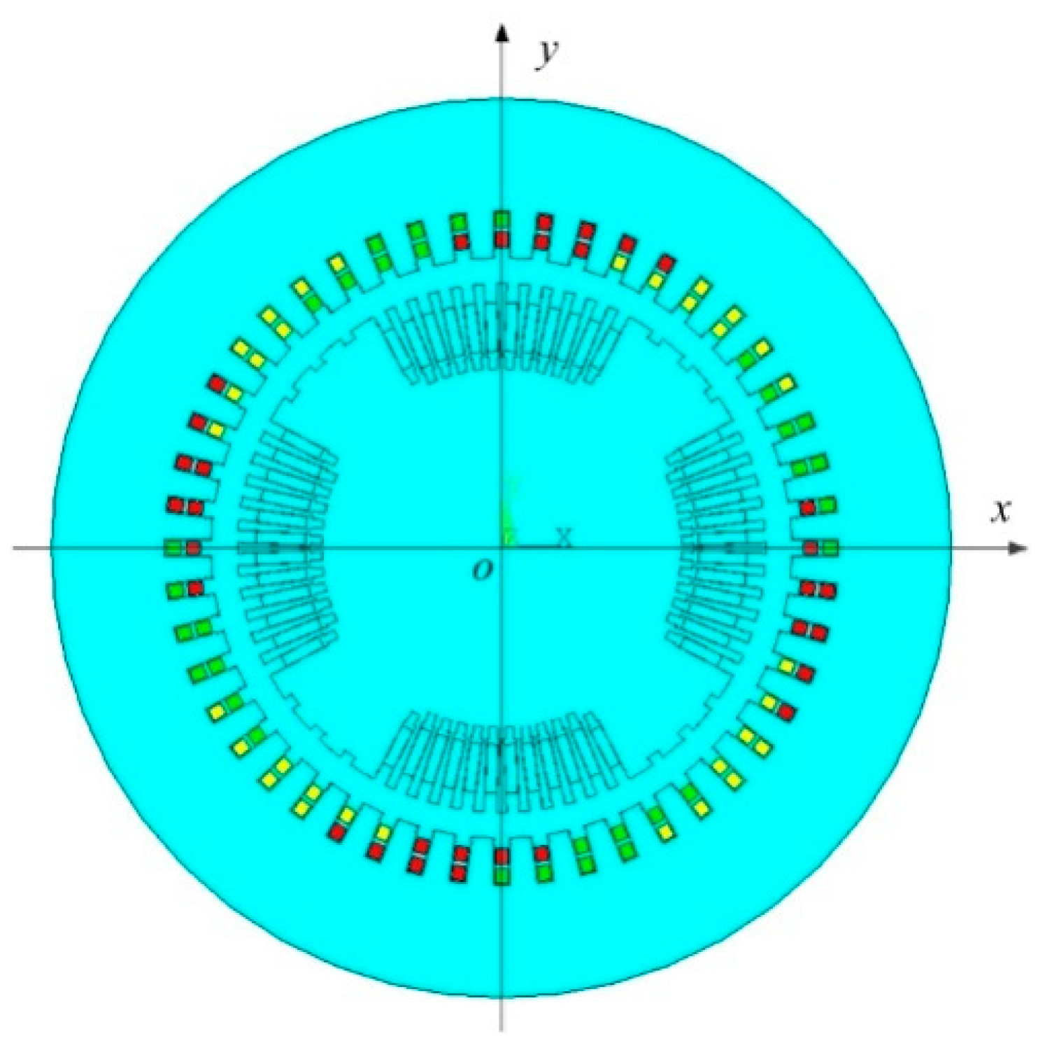
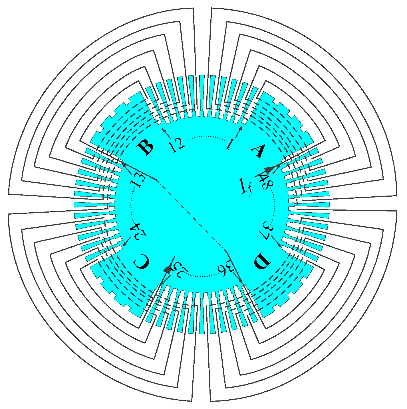
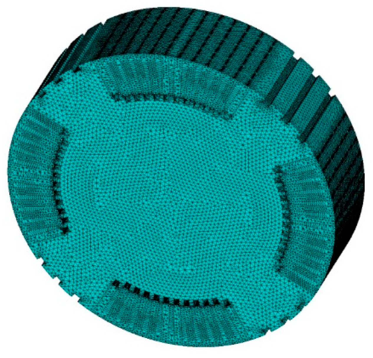
2.1. Calculation Model of Stator/Rotor Electromagnetic Field

In this paper, a TA-1100-78 type 1150 WM generator of a nuclear power plant was taken as the research object. The specific parameters are shown in Table 1.
The two-dimensional finite element model of the turbo-generator is shown in Figure 1. The x-o-y plane coordinate system was established, and the coordinate axes coincided with the rotor quadrature axes. All the space angles described in this paper took the positive direction of x-axis as the reference.
Figure 2 shows the connection of the excitation winding, where excitation current goes into A-pole and out of C-pole, B-pole and D-pole are connected by the radial conduction screw through the conduction rod in the center hole.
In order to simplify the calculation of generator magnetic field, the following assumptions were made [34,35]:
(1)
Because the simulation was two-dimensional, the end effect and the stator outer speromagnetism were ignored, considering the generator magnetic field with consistent axial distribution.
(2)
Because the eddy current effect was very small compared to the winding current and because the simulation was two-dimensional, the eddy current effect of alternating magnetic field in conductive materials was ignored, considering the generator field is a nonlinear static and steady magnetic field.
(3)
The isotropic permeability of ferromagnetic materials.
According to the above assumptions, the Poisson equation and boundary conditions in the nonlinear solution domain can be expressed as [36]:
{ x ( 1 μ A z x ) + y ( 1 μ A z y ) = J z A z | x 2 + y 2 = 1.66 2 = 0
The first kind of boundary condition of the parallel magnetic lines to the stator outer circumference is Az = 0.

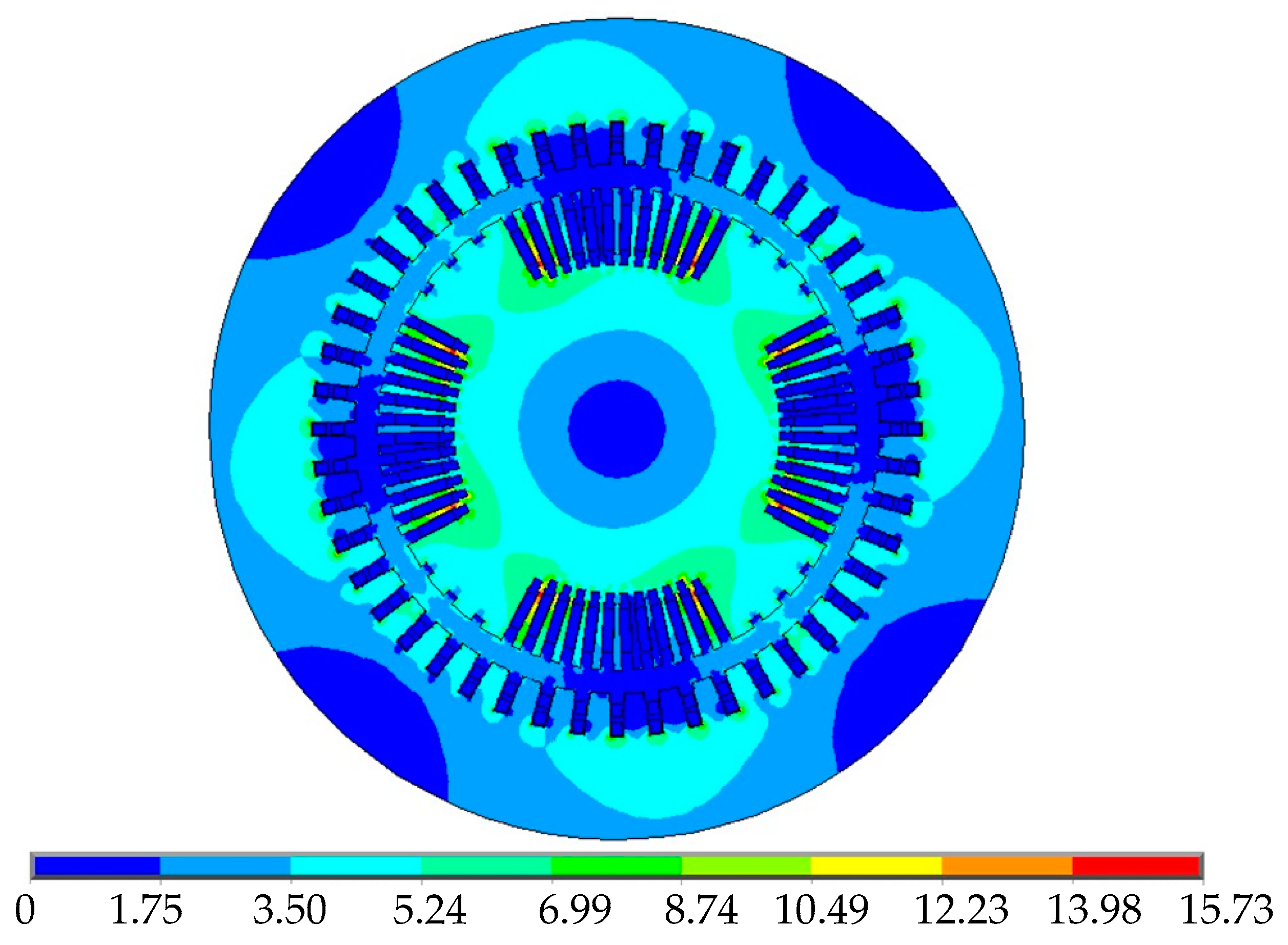
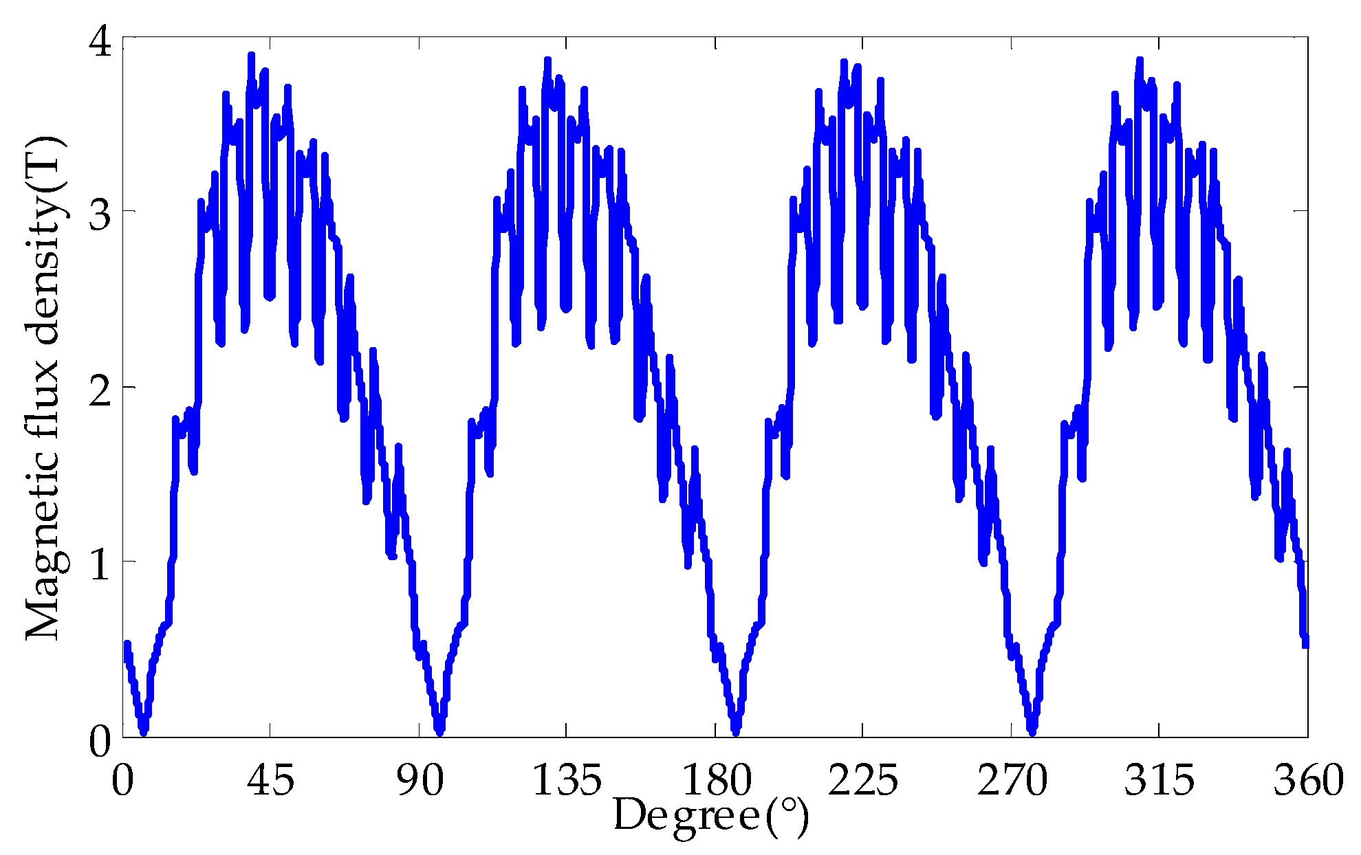
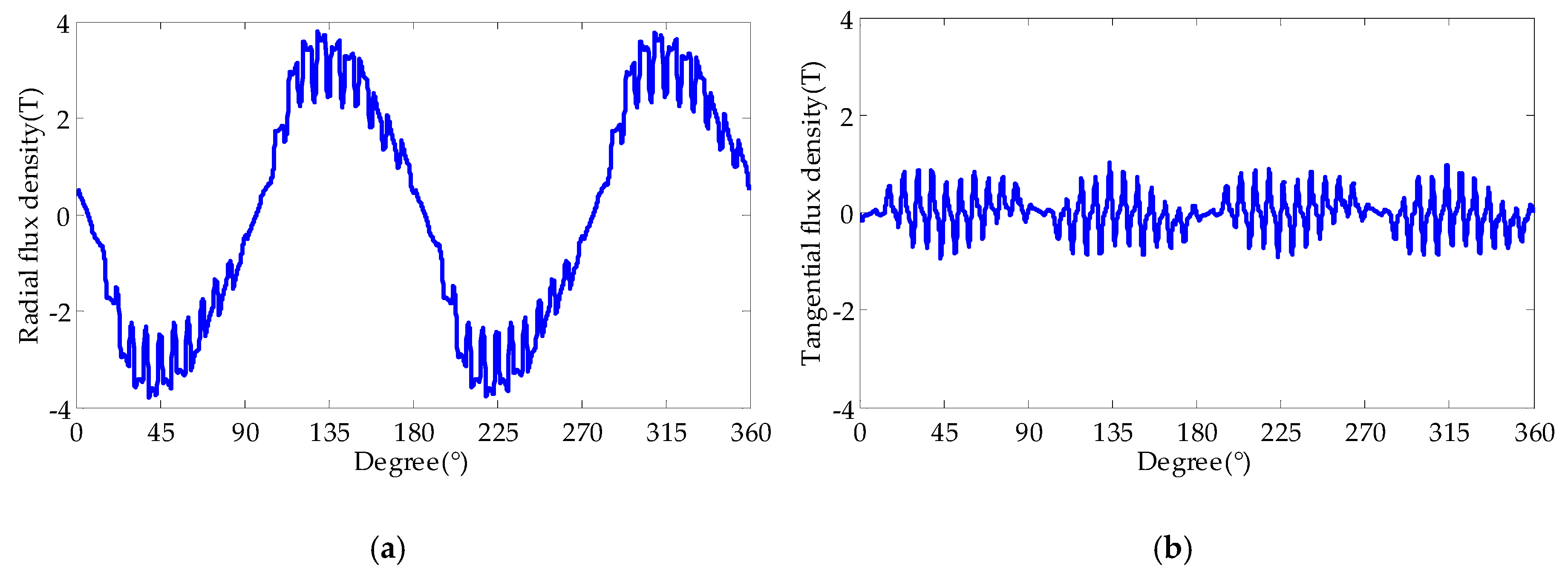
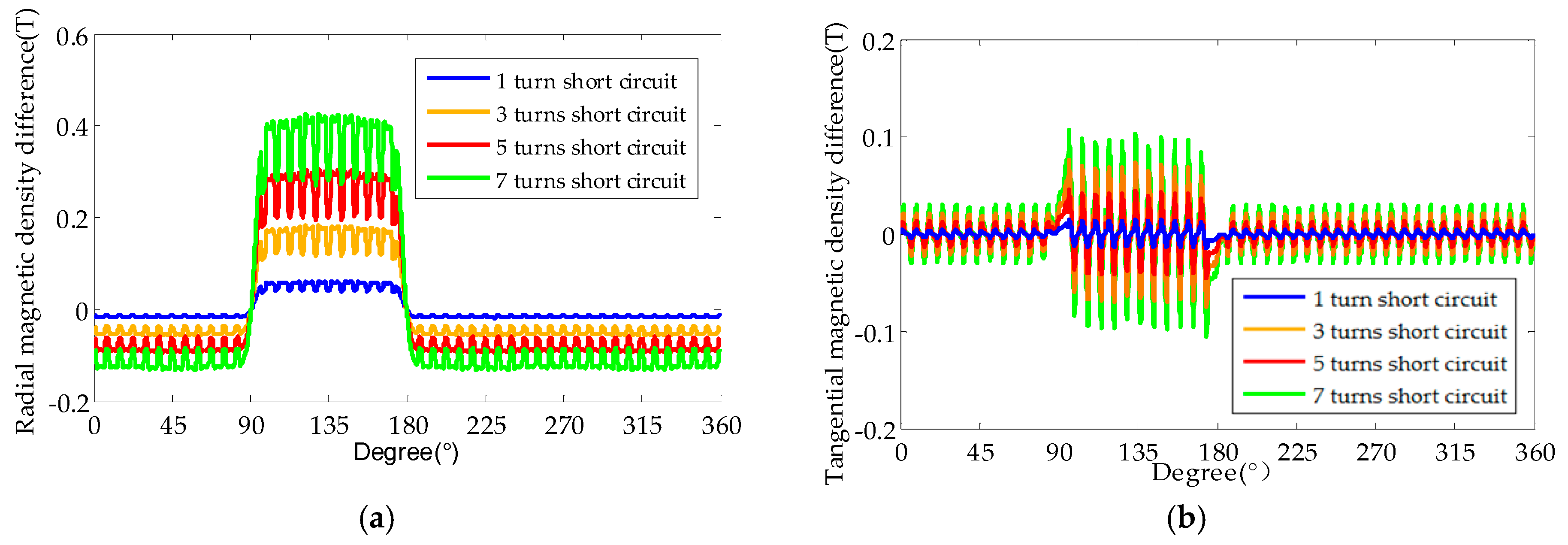
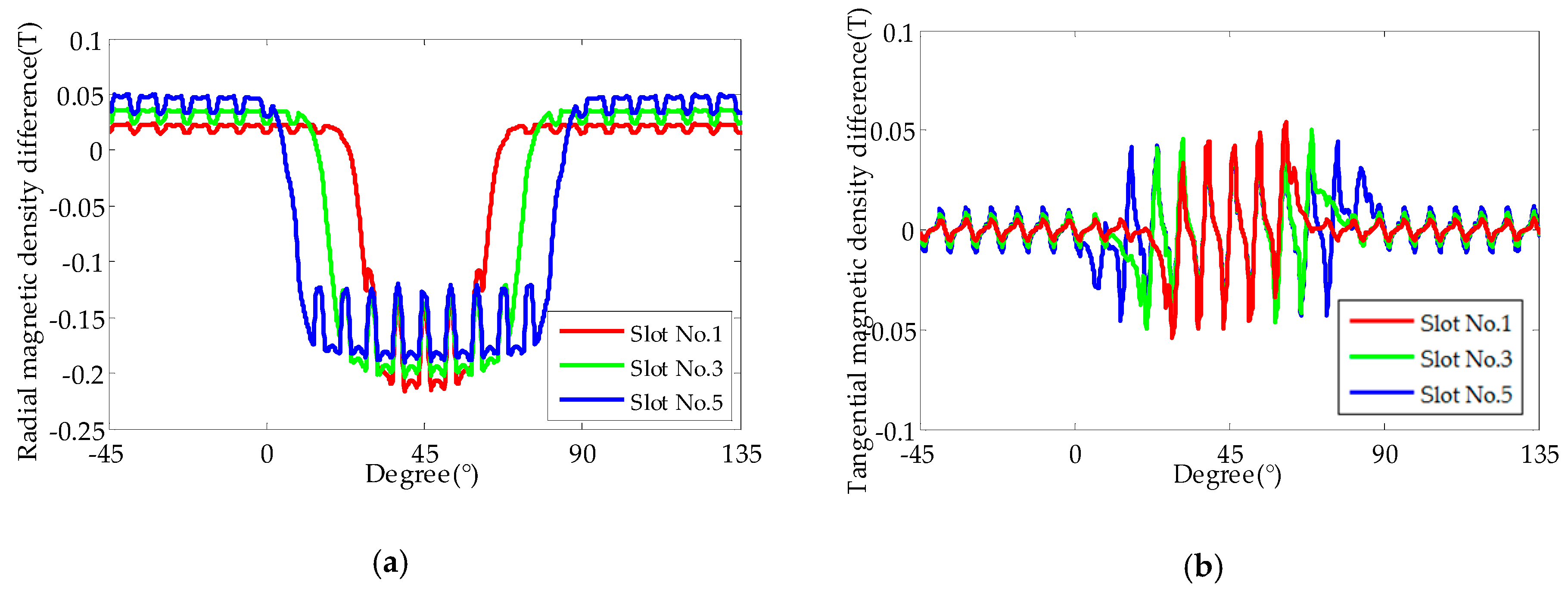
2.2. Influence of EWISC Fault on Air Gap Magnetic Field

The rated state operation parameters of the TA-1100-78 type turbo-generator were loaded into the finite element model, and the distribution characteristics of magnetic field in the generator was obtained. Figure 3 shows the distribution cloud figure of the stator and rotor magnetic field under normal rated conditions.
A circumferential path was set at the air gap at a certain distance from the circumferential surface of the rotor. Taking 3600 interpolation points on the path and starting from the x-axis shown in Figure 1, the magnetic density distribution in the rotor air gap shown in Figure 4 was obtained by anticlockwise rotation.
As can be seen from Figure 4, due to the demagnetization of armature reaction magnetomotive force on the excitation magnetomotive force, the air gap field decreased and skewed. The flux density can be decomposed into radial and tangential components according to Formula (2).
B n ( θ s ) = B x ( θ s ) cos ( θ s ) + B y ( θ s ) sin ( θ s ) B t ( θ s ) = B x ( θ s ) sin ( θ s ) B y ( θ s ) cos ( θ s )
Figure 5 shows the radial and tangential components of air gap magnetic field distribution under normal rated condition. It can be seen that the magnetic flux of air gap was mainly radial magnetic flux.
In order to study the effect of EWISC on air gap magnetic field, 1-, 3-, 5- and 7-turn short circuit faults were set up on the excitation winding in slot No. 7. The air gap magnetic density under normal condition was subtracted from the air gap magnetic density under different fault degrees, and the air gap magnetic density difference curve shown in Figure 6 was obtained.
As can be seen from Figure 6, the radial and tangential magnetic density difference of the rotor region surrounded by the fault excitation winding (between slots No. 7–18) increased with an increase in the fault degree, and the magnetic density of the remaining region changed little. This was because the current flowing through the fault winding was almost zero, which resulted in a decrease in the magnetomotive force in this area, and the air gap magnetic density decreased. The more serious the fault, the greater was the decrease in the air gap magnetic density.
Because the rotor and its excitation winding connection were symmetrical (as shown in Figure 2), the influence of EWISC fault in slot No. 1–6 and 7–12 on the air gap magnetic field distribution was the same. Therefore, this paper studied the fault position influence on air gap magnetic field by setting 3-turn EWISC in slots No. 1, 3, and 5. Figure 7 shows the air gap magnetic density difference curve between normal condition and different fault positions.
As shown in Figure 7, the closer the fault position was to the large tooth (A pole), the greater was the radial and tangential air gap magnetic density difference; the farther the fault position from the large tooth, the greater was the magnetic density change area. This was because the air gap magnetomotive force changes caused by the same fault degree were not much different. The closer the fault position to the large tooth was, the smaller was the air gap magnetic density attenuation region and the larger was the air gap magnetic density difference.
In summary, the EWISC caused the distortion of rotor air gap magnetic field and then affected the distribution of air gap magnetic density. Radial magnetic density, as the main component of air gap magnetic density, could better reflect the characteristics of magnetic field variation caused by EWISC.

3. Thermal Characteristic Analysis of EWISC

3.1. Calculation Model of Rotor Temperature Field

The specific design parameters of the TA-1100-78 type turbo-generator rotor are outlined in Table 2.
The generator rotor adopted radial and tangential two directions cooling ventilation mode. The cooling gas (hydrogen) flowed in from the subslot and flowed out through the radial duct. Taking into account the axial consistency of the rotor body, a rotor segment was modeled, which included 7 radial duct units. The model used SOLID90 3D twenty-node hexahedron element to divide the computational area using the free meshing method. The three-dimensional finite element model of the rotor is shown in Figure 8.
The following assumptions were made according to the operation and heat conduction characteristics of the generator [37]:
(1)
The subdivision planes on both sides of the model were considered as adiabatic surfaces.
(2)
The effects of stator heating on the rotor temperature field were ignored; the heat exchange of the outer surface of the rotor could be equivalent to the heat convection with air gaps.
(3)
Because the loss of the rotor surface was very small compared with the copper consumption of the winding, the surface loss and the friction loss of rotor were ignored, and copper consumption of the excitation winding was considered the only source of heat.
(4)
Because the rotor winding current was DC current, the current skin effect was ignored, and the load was considered evenly distributed on the section of the rotor winding.
(5)
The insulation effect of the winding was ignored.
Considering the above assumptions, a three-dimensional steady state heat transfer model of the rotor was established [38]:
{ x ( k x T x ) + y ( k y T y ) + z ( k z T z ) + q v = 0 k n T n | ε = α ( T | ε T f )
Before solving, the heat source and boundary conditions of the model must be clearly defined. According to the assumption, the copper consumption of the rotor winding is the only heat source, and the applied body load heat generation rate is as follows:
H g = I f 2 R f / V  
There are two main ways of rotor heat transfer: one is convective heat transfer between rotor duct and cooling gas and the other is convective heat transfer between rotor cylinder surface and air gap cooling gas.
Heat convection coefficients of the rotor ducts adopt the empirical formula [39]:
α H = 13.2 w 0.8 d 0.2 P H 0.8 ( T 0 T ) 0.56  
Heat convection coefficient of the rotor cylinder surface is as follows:
α δ = 28 ( 1 + ω / 2 )  

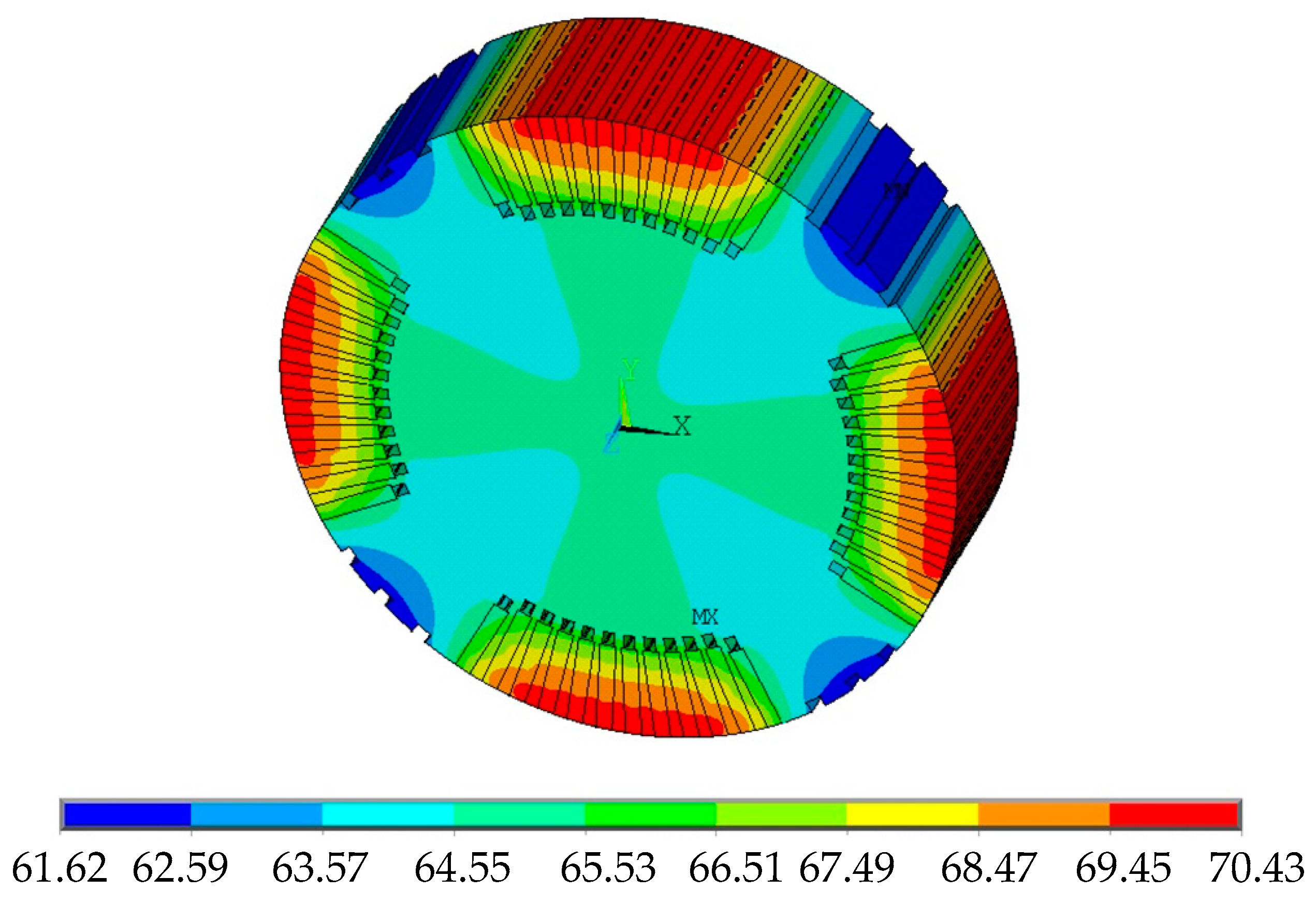
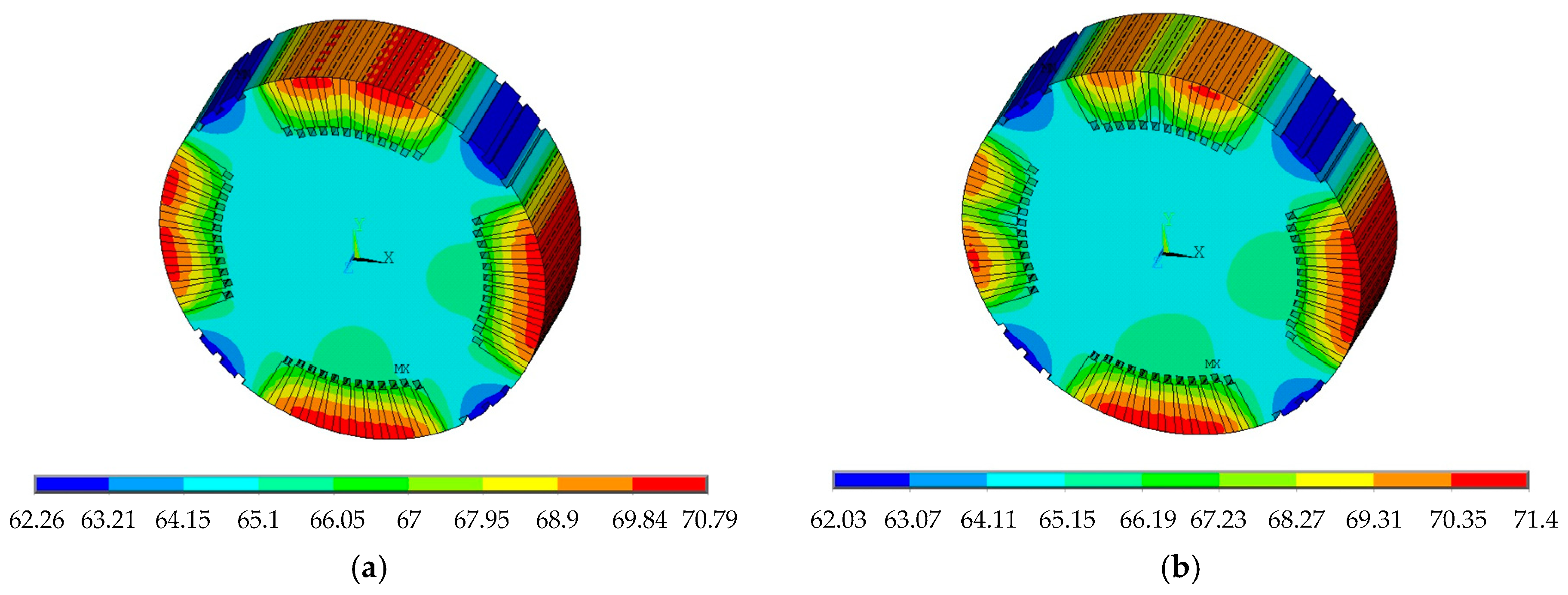
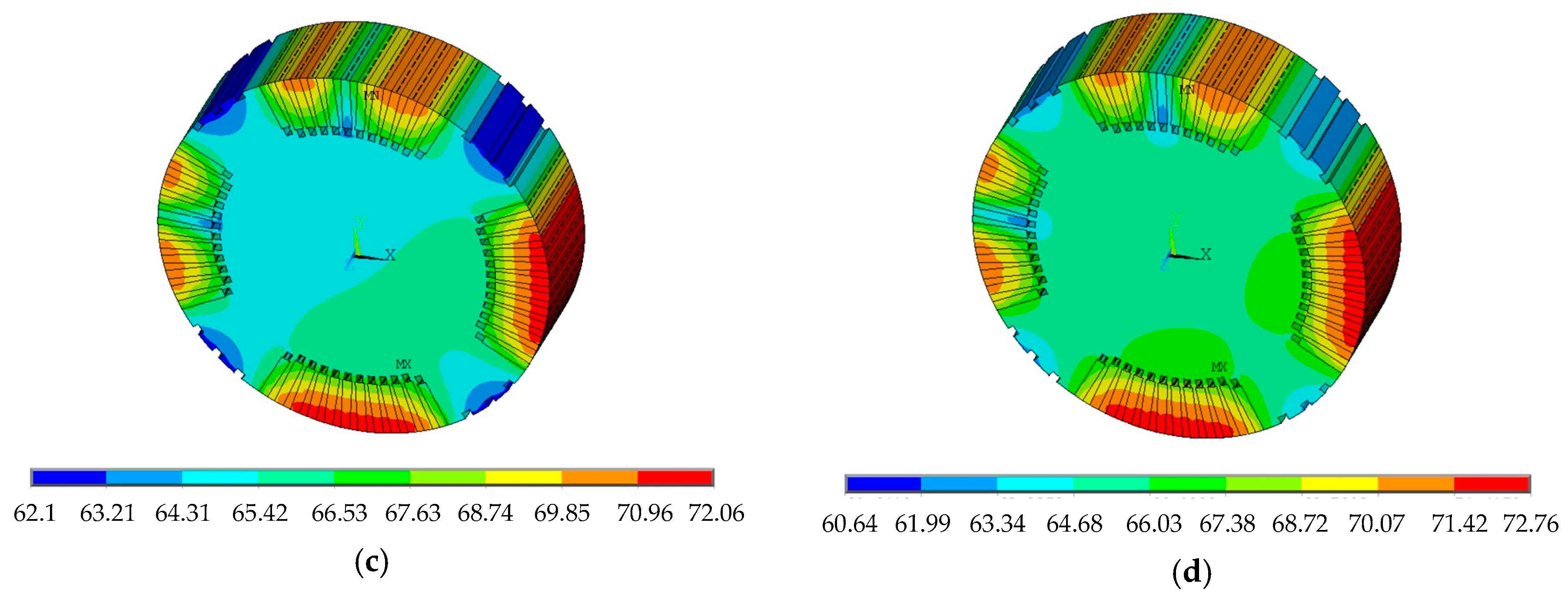
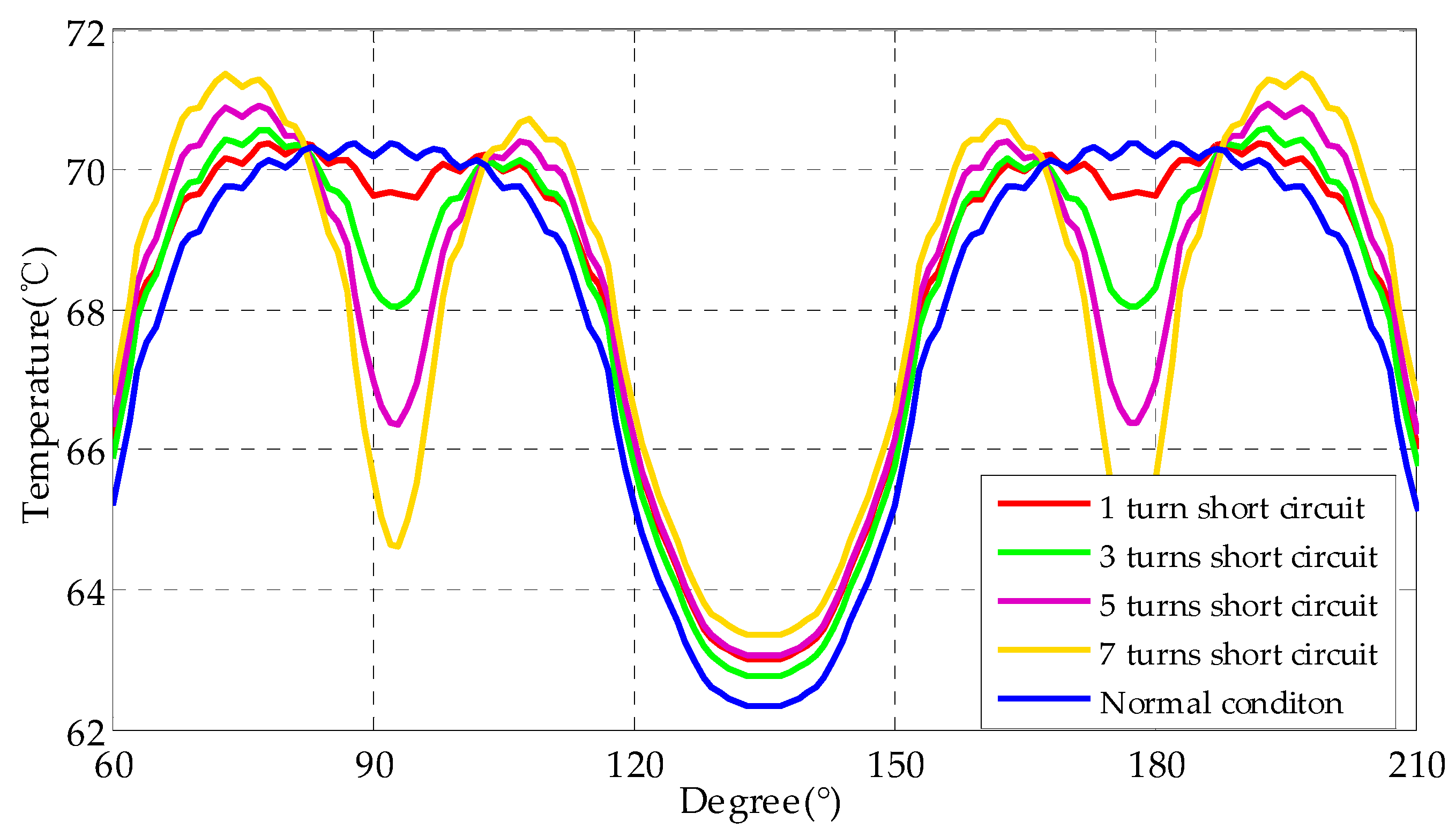
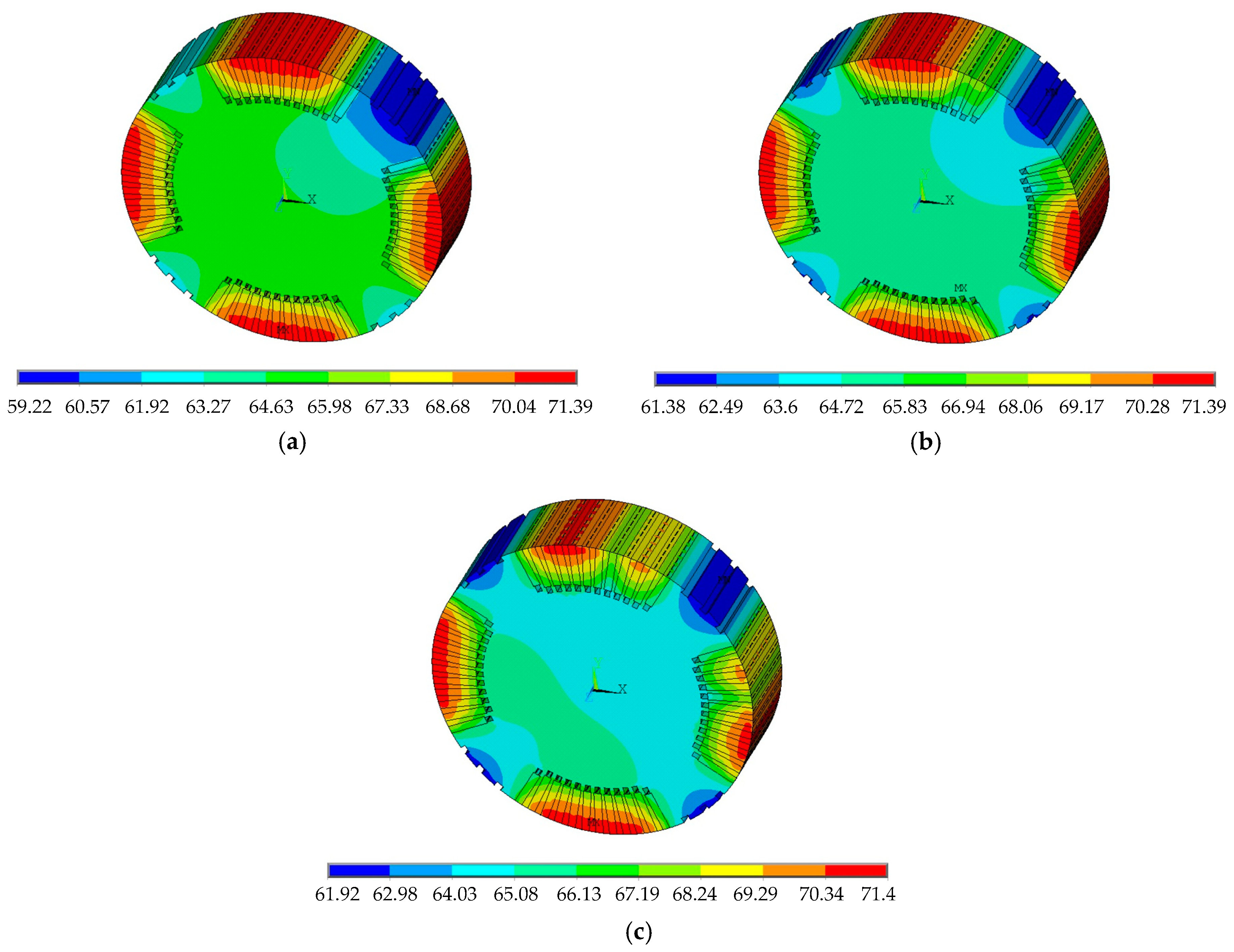
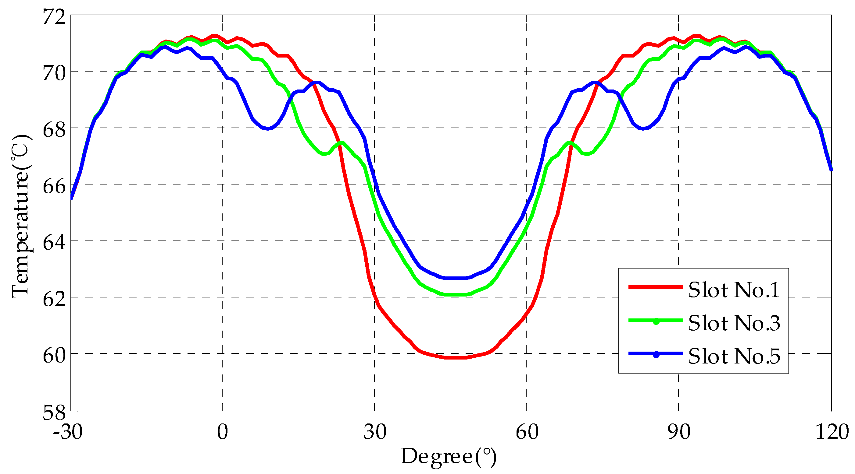
3.2. Influence of EWISC Fault on Rotor Temperature Field

According to the rotor model of the TA-1100-78 type turbo-generator, the rotor temperature field under rated load was calculated. Under rated operating conditions, the cooling gas temperature was 44.5 °C, the heat convection coefficient of the rotor radial duct was 591.4 W/(m2∙K), the heat convection coefficient of the subslot was 428.7 W/(m2∙K), and the heat convection coefficient of the rotor cylinder surface was 273 W/(m2∙K). Figure 9 shows the rotor temperature field cloud figure under normal rated condition.
The results showed that the temperature field of the whole rotor was approximately symmetrical. The temperature of the rotor winding region was the highest, exceeding 70 °C, while the lowest temperature was located in the large tooth area, which was about 61.6 °C. The axial temperature difference of the rotor was small, and the temperature difference was mainly reflected in the rotor cross section. This result was consistent with the ventilation cooling structure of large hydrogen-cooled synchronous generator. Because the heat convection coefficient of the rotor ducts was larger than that of the rotor cylinder surface, the cooling effect in the ducts was obviously better than that on the rotor cylinder surface.
Figure 10a–d shows the temperature field distribution of 1-, 3-, 5-, and 7-turn EWISC fault in slot No. 7.
As can be seen from Figure 10, the slot in which the fault winding was located was less heated, and the temperature in the adjacent part was obviously lower than that in the normal state, resulting in the asymmetric distribution of the rotor temperature field. After EWISC fault occurred, the excitation current increased with the increase in fault degree [1]. The overall temperature of the rotor rose, and the maximum temperature rose from 70.79 °C (normal condition) to 72.76 °C (7-turn short circuit).
Figure 11 is the temperature distribution curve of the rotor circumference. It can be seen that the temperature near the fault slot obviously decreased, but the temperature of the nonfault part rose to a certain extent. The temperature curve lost symmetry when the fault occurred.
Figure 12a–c shows the temperature field distribution of 3-turn EWISC fault in slot No. 1, 3, and 5.
As shown in Figure 12, the maximum temperature of the rotor was almost the same under the same fault degree, i.e., about 71.39 °C. However, the minimum temperature of the rotor was related to the fault position. From the rotor circumference surface temperature distribution curve in Figure 13, it can be seen more intuitively that the closer the fault position was to the large tooth, the greater was the distortion of temperature field distribution.

4. Thermal Stress Characteristic Analysis of EWISC

Thermal stress produced by the thermal expansion during the generator operation is an important reason for the deformation of the rotor. Based on the analysis of temperature field, the thermal element is transformed into structural element and the results of steady state temperature field analysis are taken as input of structural analysis to solve the rotor deformation and thermal stress by sequential coupling method. The statics equation is as follows:
( V B T D B d V ) U = V B T D ε 0 d V  
ε 0 = Δ T [ α x , α y , α z , 0 , 0 , 0 ] T  
σ = D ( B U ε 0 )  
Based on the analysis of three-dimensional temperature field of rated load operation state, the three-dimensional thermal stress field was simulated. Figure 14 is the von Mises stress cloud figure of rotor under normal rated condition. From the simulation results, the axial thermal stress of the rotor was basically consistent; the main difference was still reflected in the cross section distribution. Because the expansion coefficient of excitation winding and rotor core was different and the temperature of excitation winding was higher than that of rotor core, the thermal stress of excitation winding was relatively higher. According to Figure 14, the maximum stress of rotor could reach 624 MPa, while the yield strength of the TA-1100-78 type turbo-generator rotor E0.002 = 650 MPa, the maximum stress of rotor under rated load condition was less than the yield strength of rotor. Therefore, the rotor would not yield, i.e., the thermal deformation of the rotor was a recoverable elastic deformation that did not cause plastic deformation of the rotor.
Figure 15 shows the maximum thermal stress of the rotor under different EWISC fault degrees. This caused a slight increase in the maximum thermal stress, but still did not exceed the yield strength of the rotor.
Figure 16 shows the thermal stress distribution around the rotor at different EWISC fault degrees in slot No. 7. The result showed that the thermal stress near the fault slot changed. EWISC caused temperature drop in the fault slot and its adjacent parts, and the local temperature difference increased. With an increase in the fault degree, the local thermal stress increased.
Figure 17 shows the thermal stress distribution around the rotor with a 3-turn EWISC fault at different fault positions. From the figure, it can be seen that the thermal stress of the rotor near the large tooth (A pole) had changed. When the fault occurred, the temperature of the large tooth decreased. The thermal stress increased with the increase in local temperature difference. The closer the fault position was to the large tooth, the greater was the thermal stress.

5. Conclusions

In this paper, taking a TA-1100-78 type turbo-generator as research object, the two-dimensional finite element electromagnetic model of stator and rotor and the three-dimensional finite element heat transfer model of rotor segment were established. The electromagnetic field, temperature field, and stress field under EWISC fault were simulated and analyzed. Main conclusions are as follows:
(1)
The EWISC fault will weaken the air gap magnetic field of the generator and cause an unbalanced distribution of the magnetic field. The greater the fault degree is, the closer the fault position is to the large tooth, and the more serious is the attenuation of air gap magnetic density.
(2)
The EWISC fault will cause the distortion of the temperature field of the rotor. The more serious the short circuit is, the closer the fault position is to the large tooth, and the more serious is the temperature imbalance of the rotor.
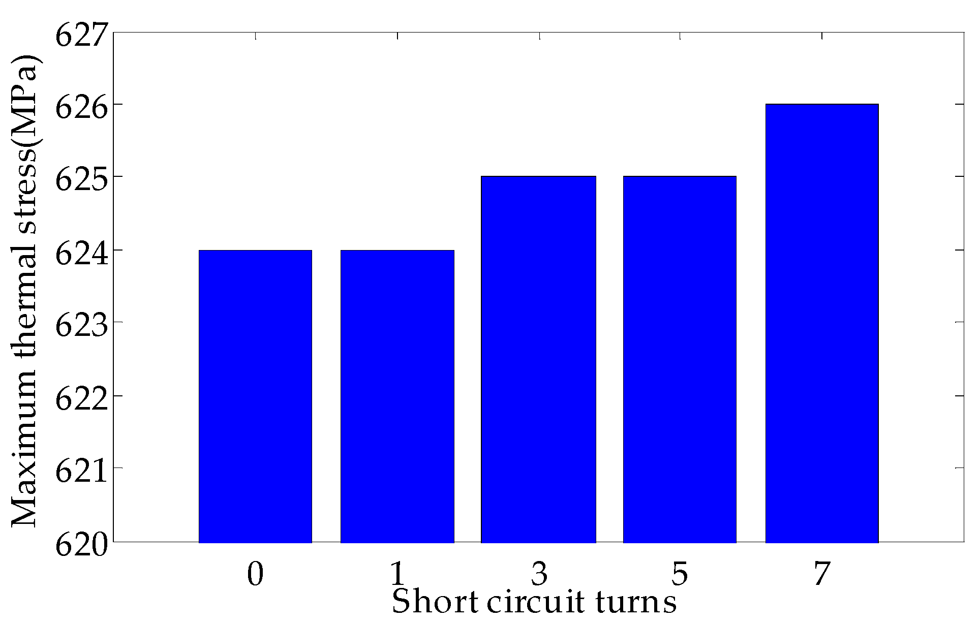
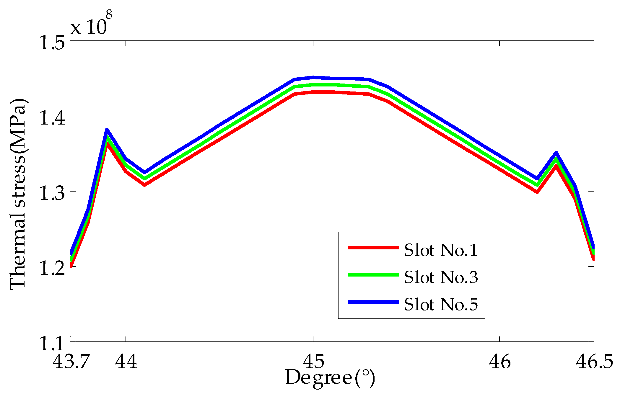
(3)
The EWISC fault will increase the local thermal stress of rotor. The more serious the fault is, the closer the fault is to the large tooth, and the greater is the local temperature difference of rotor is, the greater the thermal stress.
(4)
The EWISC fault will not cause the overall thermal stress of the rotor to exceed the yield limit of the material. The EWISC will not cause the plastic deformation of the rotor and will not damage the rotor structure. The thermal deformation of the rotor is a recoverable elastic deformation.
(5)
The EWISC fault causes the unbalanced distribution of the rotor temperature field, which causes the different elastic deformation of the rotor. This will lead to the thermal bending of the rotor, resulting in unbalanced vibration of the rotor. Previous studies have only considered the rotor vibration caused by electromagnetic imbalance [6], which is obviously not comprehensive enough, so it is worthwhile to consider the rotor vibration caused by electromagnetic and thermal imbalance simultaneously.

Author Contributions

M.M., Y.L. and Y.W. supervised all process; M.M. and Y.W. implemented simulation; Y.L. analyzed the data; C.D. checked paper format.

Funding

This research was funded by Natural Science Foundation of Hebei Province under Grant, E2016502031 and Fundamental Research Funds for the Central Universities under Grant, 2016XS97.

Acknowledgments

We would like to thank the China General Nuclear Power Group for providing data support. We would also like to thank the State Key Laboratory of Alternate Electrical Power System with Renewable Energy Sources for providing the laboratory.

Conflicts of Interest

The authors declare no conflict of interest.

Notations

Azz axis component of the vector magnetic potential
μpermeability of magnetic conductive material
Jzz axis component of the current density
θsspace electric angle
Bxx-components of magnetic density
Byy-components of magnetic density
Bnradial components of magnetic density
Bttangential components of magnetic density
kxheat transfer coefficients of the media in x direction
kyheat transfer coefficients of the media in y direction
kzheat transfer coefficients of the media in z direction
knheat transfer coefficients of the media in boundary normal direction
qvheating rate of unit volume
Ttemperature of the model calculation area
Tftemperature of the surrounding fluid
αheat convection coefficient
εmodel boundary
Hgbody load heat generation rate
Ifexcitation current
Rfresistance of excitation winding
Vvolume of excitation winding
whydrogen flow rate
wsrotor angular speed
dequivalent diameter
PHfluid pressure
T0zero centigrade (K)
αHheat convection coefficients of the rotor ducts
αδheat convection coefficient of the rotor cylinder surface
Belement stress matrix
Delastic stiffness matrix
ε0element thermal stress matrix
Unode displacement vector matrix
Δ T temperature rise
αxx-direction thermal expansion coefficients
αyy-direction thermal expansion coefficients
αzz-direction thermal expansion coefficients
σstress vector

References

  1. Kinitsky, V. Calculation of internal fault currents in synchronous machines. IEEE Trans. Power Appar. Syst. 1965, 84, 381–389. [Google Scholar] [CrossRef]
  2. Kinitsky, V. Digital computer calculation of internal fault currents in a synchronous machine. IEEE Trans. Power Appar. Syst. 1968, 87, 1675–1679. [Google Scholar] [CrossRef]
  3. Reichmeider, P.; Gross, C.; Querrey, D.; Novosel, D.; Salon, S. Internal faults in synchronous machines. I. The machine model. IEEE Trans. Energy Convers. 2000, 15, 376–379. [Google Scholar] [CrossRef]
  4. Megahed, A.; Malik, O. Synchronous generator internal fault computation and experimental verification. IEE Proc. Gener. Transm. Dis. 1998, 145, 604–610. [Google Scholar] [CrossRef]
  5. Li, R.; Li, C.; Peng, X.; Wei, W. Electromagnetic vibration simulation of a 250-mw large hydropower generator with rotor eccentricity and rotor deformation. Energies 2017, 10, 2155. [Google Scholar] [CrossRef]
  6. Braun, D.; Koeppl, G. Intermittent line-to-ground faults in generator stator windings and consequences on neutral grounding. IEEE Trans. Power Del. 2010, 25, 876–881. [Google Scholar] [CrossRef]
  7. Nadarajan, S.; Panda, S.; Bhangu, B.; Gupta, A. Hybrid model for wound-rotor synchronous generator to detect and diagnose turn-to-turn short-circuit fault in stator windings. IEEE Trans. Ind. Electron. 2015, 62, 1888–1900. [Google Scholar] [CrossRef]
  8. Li, Y.; Li, H.; Zhao, H. The new criterion on inter turn short-circuit fault diagnose of steam turbine generator rotor windings. Proc. CSEE 2003, 23, 112–116. [Google Scholar]
  9. Wu, Y.; Li, Y.; Li, H. Diagnosis of non-Salient pole synchronous generator rotor’s typical faults based on shaft voltage. Trans. CES 2010, 25, 178–184. [Google Scholar]
  10. Wu, Y.; Li, Y. Experimental study of rotor inter-turn short circuit fault diagnosis in turbine generator based on characteristic frequency of end-leakage-flux. Trans. CES 2014, 29, 107–115. [Google Scholar]
  11. Nippes, P. Early warning of developing problems in rotating Machinery as provided by monitoring shaft Voltages and grounding currents. IEEE Trans. Energy Convers. 2004, 19, 340–345. [Google Scholar] [CrossRef]
  12. Wu, Y.; Li, Y. Diagnosis of Rotor Winding Interturn Short-Circuit in Turbine Generators Using Virtual Power. IEEE Trans. Energy Convers. 2015, 30, 183–188. [Google Scholar]
  13. Zhang, C.; Xia, L.; Wu, Z.; Hou, X.; Huang, H. Transfer law of fault characteristics of interturn short circuit in synchronous generator rotor winding. Power Syst. Prot. Control 2011, 39, 52–57. [Google Scholar]
  14. Zhang, G.; Wu, J.; Hao, L. Analysis on the Amplitude and Frequency Characteristics of the Rotor Unbalanced Magnetic Pull of a Multi-Pole Synchronous Generator with Inter-Turn Short Circuit of Field Windings. Energies 2018, 11, 60. [Google Scholar] [CrossRef]
  15. Zhang, G.; Wu, J.; Hao, L. Fast calculation model and theoretical analysis of rotor unbalanced magnetic pull for inter-turn short circuit of field windings of non-salient pole generators. Energies 2017, 10, 732. [Google Scholar] [CrossRef]
  16. Hao, L.; Wu, J.; Zhou, Y. Theoretical analysis and calculation model of the electromagnetic torque of nonsalient-pole synchronous machines with interturn short circuit in field windings. IEEE Trans. Energy Convers. 2015, 30, 110–121. [Google Scholar] [CrossRef]
  17. Albright, D.R. Interturn short-circuit detector for turbine-generator rotor windings. IEEE Trans. Power Appar. Syst. 1971, 90, 478–483. [Google Scholar] [CrossRef]
  18. Fišer, R.; Lavrič, H.; Bugeza, M.; Makuc, D. Computations on Magnetic Field Anomalies in Synchronous Generator Due to Rotor Excitation Coil Faults. IEEE Trans. Magn. 2013, 49, 2303–2306. [Google Scholar] [CrossRef]
  19. Wu, Y.; Ma, M.; Li, Y. A new detection coil capable of performing online diagnosis of excitation winding short-circuits in steam-turbine generators. IEEE Trans. Energy Convers. 2018, 33, 106–115. [Google Scholar]
  20. Wang, L.; Li, Y.; Li, J. Diagnosis of inter-turn short circuit of synchronous generator rotor winding based on volterra kernel identification. Energies 2018, 11, 2524. [Google Scholar] [CrossRef]
  21. Li, H.; Li, J. Review on temperature computation and application in electric machine. J. North China Elect. Power Univ. (Natl. Sci. Ed.) 2005, 32, 1–5. [Google Scholar]
  22. Lu, Y.; Li, W.; Ma, X.; Jin, H. Numerical simulation of temperature field in rotor of large turbo generator with air-coolant. Proc. CSEE 2007, 27, 7–13. [Google Scholar]
  23. Li, W.; Hou, Y.; Zhou, F.; Cheng, S. Calculating method of rotor temperature with radial and tangential air-cooling system. Proc. CSEE 2000, 20, 74–78. [Google Scholar]
  24. Li, W.; Li, J.; Li, D. Influence of variable section rotor ventilation ducts on temperature and fluid fields of a full air-cooled large hydro-generator rotor. Trans. CES 2017, 32, 42–49. [Google Scholar]
  25. Li, H.; Li, J. Analysis and calculation of turbogenerators stator temperature field on cooling circuit blocked. Proc. CSEE 2005, 25, 163–168. [Google Scholar]
  26. Yin, Q.; Li, W.; Yu, H.; Sun, H. Calculation and analysis of electromagnetic field and temperature field under broken strands for a large synchronous generator. Trans. CES 2011, 26, 59–67. [Google Scholar]
  27. Li, W.; Han, J.; Huo, F.; Zhou, X.; Zhang, Y.; Li, Y. Influence of the end ventilation structure change on the temperature distribution in the end region of large water-hydrogen-hydrogen cooled turbogenerator. IEEE Trans. Energy Convers. 2013, 28, 278–288. [Google Scholar]
  28. Li, W.; Li, Y.; Su, Y.; Wang, P.; Liu, W. Research on stator main insulation temperature field of air-cooled turbo-generator after main insulation shelling. Energies 2018, 11, 1101. [Google Scholar] [CrossRef]
  29. Xie, Y.; Guo, J.; Chen, P.; Li, Z. Coupled fluid-thermal analysis for induction motors with broken bars operating under the rated load. Energies 2018, 11, 2024. [Google Scholar] [CrossRef]
  30. Cao, Z.; Li, W.; Li, J.; Zhang, X.; Li, D.; Zhang, M. Research on the temperature field of high-voltage high power line start permanent magnet synchronous machines with different rotor cage structure. Energies 2017, 10, 1829. [Google Scholar] [CrossRef]
  31. Li, L.; Li, W.; Li, D.; Li, J.; Fan, Y. Research on strategies and methods suppressing permanent magnet demagnetization in permanent magnet synchronous motors based on a multi-physical field and rotor multi-topology structure. Energies 2018, 11, 40. [Google Scholar] [CrossRef]
  32. Li, D.; Wen, Y.; Li, W.; Feng, B.; Cao, J. Three-dimensional temperature field calculation and analysis of an axial-radial flux-type permanent magnet synchronous motor. Energies 2018, 11, 1208. [Google Scholar] [CrossRef]
  33. Cao, Z.; Li, W.; Zhang, X.; Fan, Y.; Zeng, J. Influence of single/dual ventilation path on fluid field and temperature field of HVLSSR-PMSM with air-cooled hybrid ventilation systems. Energies 2018, 11, 1343. [Google Scholar] [CrossRef]
  34. Xie, Y.; Wang, L.; Yu, Y. Magnetic field variation in squirrel-cage induction motor operating on asymmetric rotor. Proc. CSEE 2011, 31, 100–108. [Google Scholar]
  35. Sprooten, J.; Maun, J. Influence of saturation level on the effect of broken bars in induction motors using fundamental electromagnetic laws and finite element simulations. IEEE Trans. Energy Convers. 2009, 24, 557–564. [Google Scholar] [CrossRef]
  36. Zhang, D.; Li, W.; Zhou, F.; Hou, Y. Numerical calculation of air gap magnetic field of a salient synchronous generator with the consideration of the effect of turn insulation. Proc. Int. Conf. Power Syst. Technol. 2002, 2, 774–778. [Google Scholar]
  37. Wang, Y.; Yang, L.; Chen, X.; Sun, F. Study on 3D thermal field and thermal stress field of the induction motor rotor. Elect. Mach. Control 2010, 14, 27–32. [Google Scholar]
  38. Li, W.; Ding, S.; Jin, H.; Luo, Y. Numerical Calculation of Multicoupled Fields in Large Salient Synchronous Generator. IEEE Trans. Magn. 2007, 43, 1449–1452. [Google Scholar] [CrossRef]
  39. Wei, Y.; Meng, D.; Wen, J. Heat Transfer Inner Electric Machines; China Machine Press: Beijing, China, 1998. [Google Scholar]
Figure 1. 2D stator and rotor model.
Energies 11 02626 g001
Figure 2. Connection of the excitation winding.
Energies 11 02626 g002
Figure 3. Stator and rotor magnetic field distribution cloud figure.
Energies 11 02626 g003
Figure 4. Air gap magnetic field distribution under normal rated condition.
Energies 11 02626 g004
Figure 5. Radial and tangential components of air gap magnetic field distribution under normal rated condition. (a) Radial component; (b) Tangential components.
Energies 11 02626 g005
Figure 6. Air gap magnetic density difference between normal condition and different fault degrees. (a) Radial magnetic density difference; (b) Tangential magnetic density difference.
Energies 11 02626 g006
Figure 7. Air gap magnetic density difference between normal condition and different fault positions. (a) Radial magnetic density difference; (b) Tangential magnetic density difference.
Energies 11 02626 g007
Figure 8. Three-dimensional finite element model of rotor.
Energies 11 02626 g008
Figure 9. Rotor temperature field cloud figure under normal rated condition.
Energies 11 02626 g009
Figure 10. Temperature field distribution of different fault degree. (a) 1-turn short circuit; (b) 3-turn short circuit; (c) 5-turn short circuit; (d) 7-turn short circuit.
Energies 11 02626 g010aEnergies 11 02626 g010b
Figure 11. Temperature curve of different fault degrees.
Energies 11 02626 g011
Figure 12. Temperature field distribution of different short circuit position. (a) Short circuit fault in slot No. 1; (b) Short circuit fault in slot No. 3; (c) Short circuit fault in slot No. 5.
Energies 11 02626 g012
Figure 13. Temperature curve of different fault positions.
Energies 11 02626 g013
Figure 14. Rotor von Mises stress cloud figure.
Energies 11 02626 g014
Figure 15. Rotor maximum thermal stress of different fault degree.
Energies 11 02626 g015
Figure 16. Thermal stress distribution near the fault slot of different fault degree.
Energies 11 02626 g016
Figure 17. Thermal stress distribution in large tooth area of different short circuit position.
Energies 11 02626 g017
Table 1. The parameters of TA-1100-78 type generator.
ItemValue
Rated capacity/MVA1277.8
Rated power/MW1150
Rated voltage/kV24
Rated current/A30,739
Rated power factor0.9
Number of pole-pairs2
Rated frequency/Hz50
Rated rotating speed /rpm1500
No-load excitation current/A2189
Rated excitation current/A5889
Table 2. Rotor design parameters of TA-1100-78 type turbo-generator.
ItemValue
Rotor outer diameter/mm1950
Rotor length/mm7950
Number of rotor slots48
Number of rotor deep slots40
Number of rotor shallow slots8
Slot width/mm46
Deep slots depth/mm269
Shallow slots depth/mm244
Subslot width/mm32
Subslot depth/mm42.15
Rotor radial duct pitch/mm75
Number of turns of each deep slot7
Number of turns of each shallow slot6

