Engineering Simulation Tests on Multiphase Flow in Middle- and High-Yield Slanted Well Bores
Abstract
:1. Introduction
2. Experimental System of Multiphase Pipe Flow
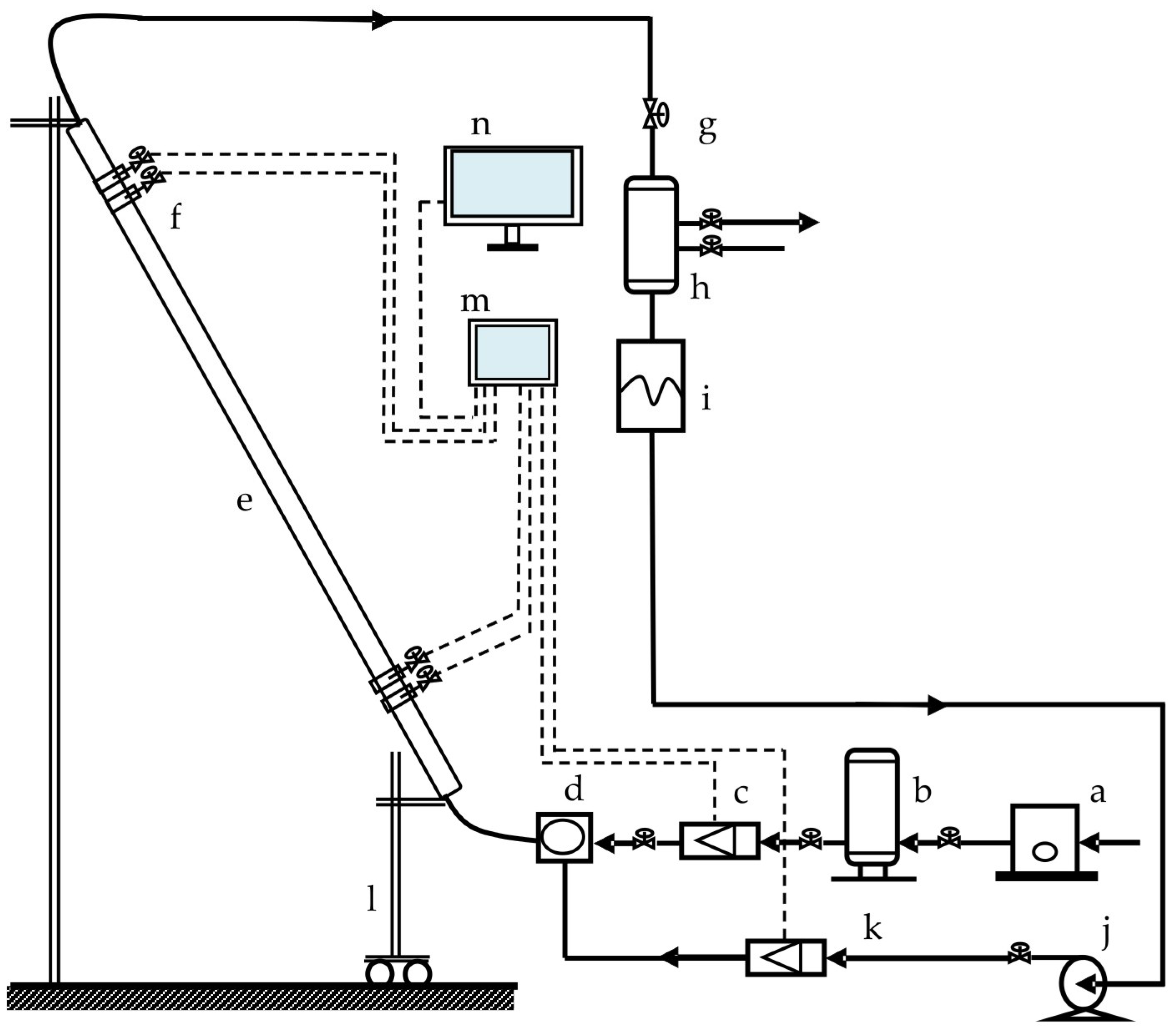
2.1. Experimental Apparatus
2.2. Experimental Contents
2.2.1. Preparation before Experiment
- Before the commencement of the experiment, the pipeline airtightness and clearance of process pipeline pathway were firstly checked. Then, it was checked whether the compressor, water pump, each instrument, and recording software could normally work.
- Experimental contents were determined, and the inclined angles of test pipes were selected based on the testing program.
- The test stand was raised with a hoist; when a required angle was attained, the lifting hoist was stopped.
- The air inlet and outlet valve switches of the selected test pipe were opened, and the valves of other test pipes were closed.
- Inspection was repeated to ensure the process was correct, the experimental pipeline ports were open, and there was no pressure buildup phenomenon.
2.2.2. Experimental Procedure
- The software system of the console was opened, and the testing string inclination was adjusted.
- The air compressor was started, and the water pump was opened on the console.
- The fluid and gas volumes entering the string were adjusted. The gas volume was adjusted by slowly adjusting the opening of the air inlet valve, whereas the fluid volume was adjusted by slowly adjusting the pump frequency and the opening of the reflux valve; simultaneously, the instrument readings on the console were observed until the target values were reached.
- After the target values were reached, the experimental phenomena were observed, and the pressure, differential pressure, temperature, fluid volume, and gas volume displayed on the instrument were recorded.
- The experimental data recording time range was set, the test data was saved, a high speed camera was used to take photographs, and the fluid flow patterns in the pipe were recorded and saved.
- After the gas and liquid in test string was stopped with quick closing valve and the liquid was still, the height of liquid in the plexi-glass tubular was read, and the liquid holdup was figured out.
- The gas volume and the liquid volume in the testing string as well as the inclined angle of the string were readjusted. Then, the above procedures were repeated, and the gas flow rate, liquid flow rate, pressure, differential pressure, temperature, flow behavior, and liquid holdup tested at different inclined angles were recorded.
- After the experiment was finished, the water pump and air compressor were shut off, the test stand was placed horizontally, and the power switches of the computer and console were turned off.
2.2.3. Experimental Parameters
3. Experimental Analysis
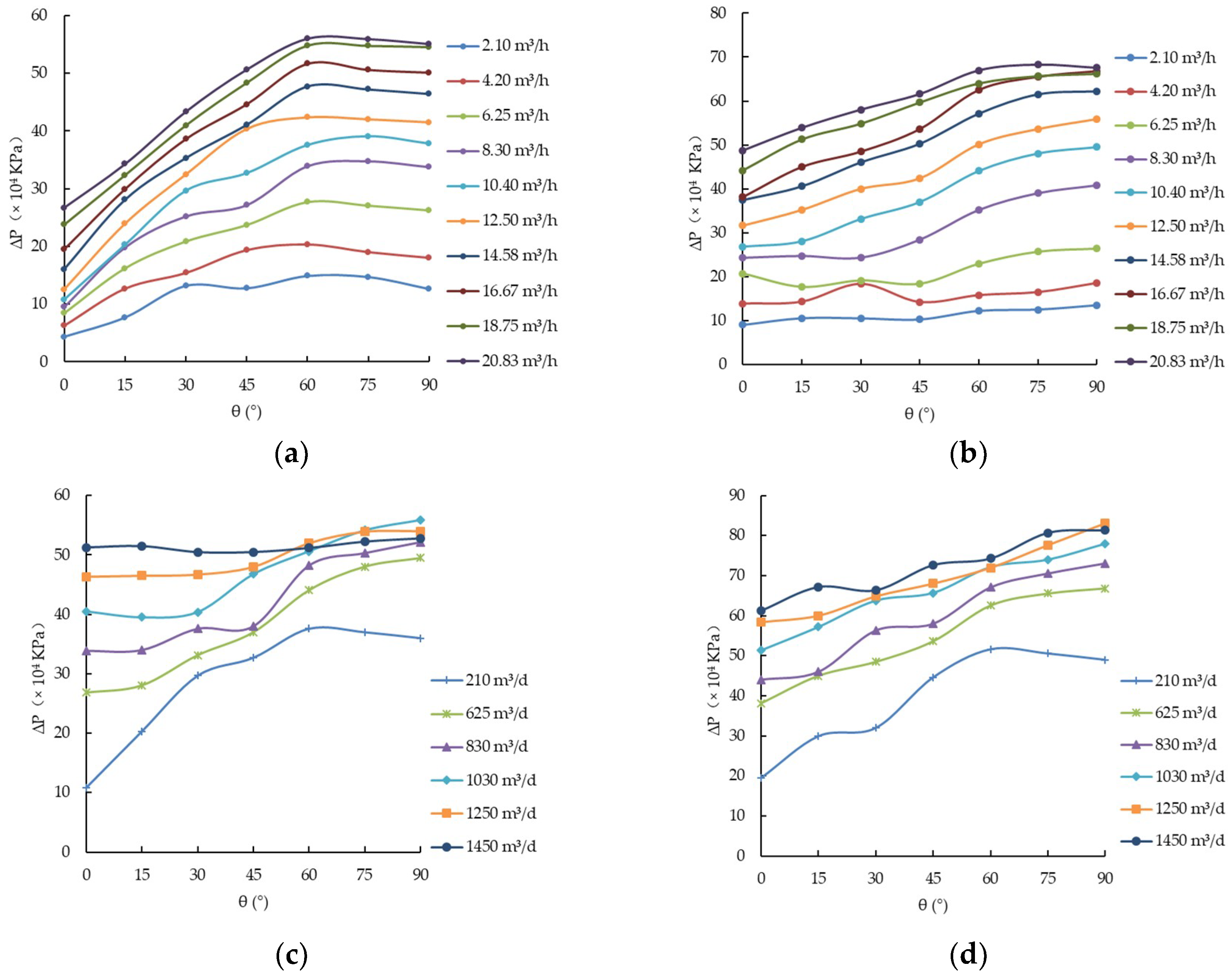
3.1. Analysis of Factors Affecting Pressure Drawdown
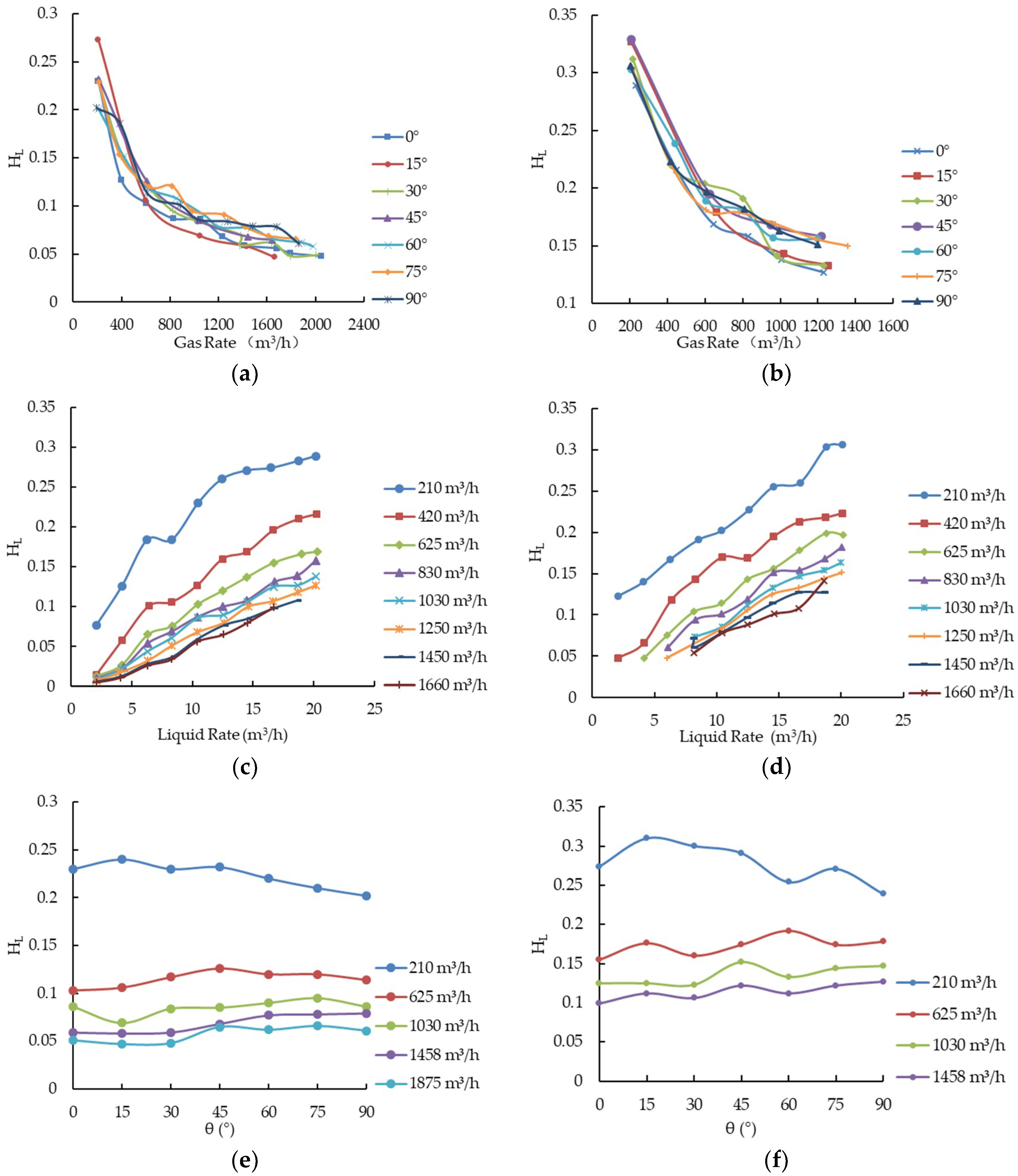
3.2. Analysis on Influential Factors of Liquid Holdup
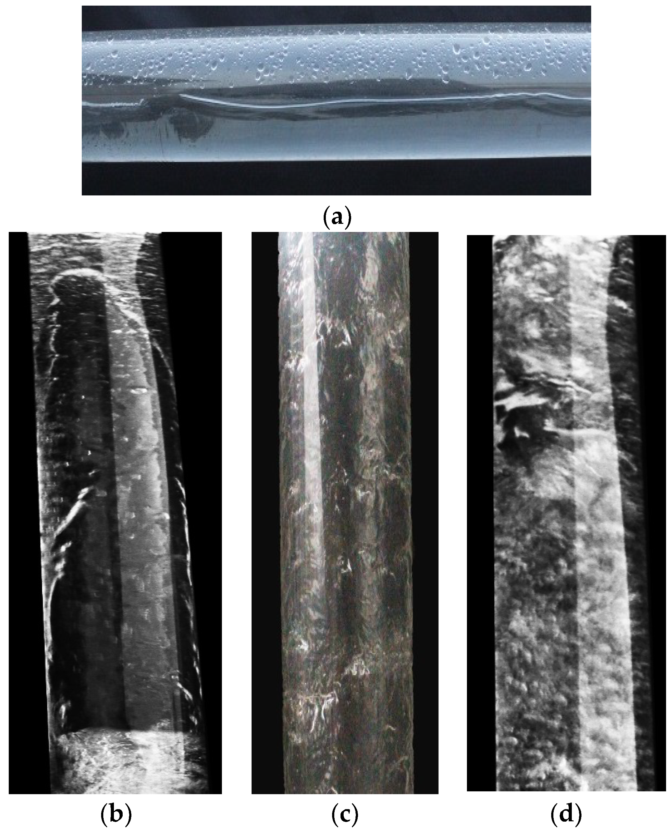
3.3. Flow Pattern Variation at Different Inclined Angles
3.4. Verification of Flow Pattern Maps
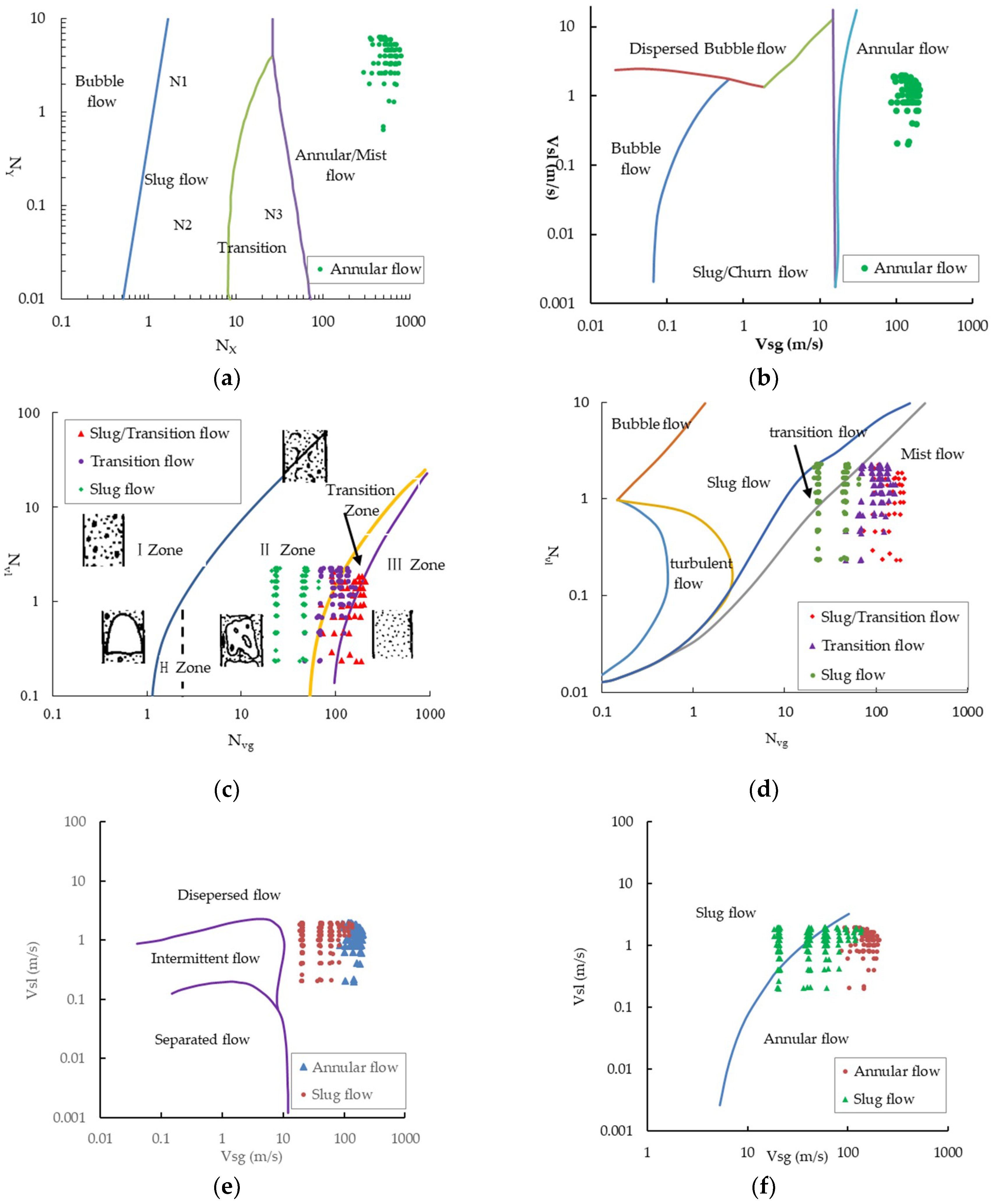
- For the annular flow, Beggs–Brill flow pattern map, Mukherjee flow pattern map, and Aziz flow pattern map were the most accurate, i.e., out of the 469 groups of experiments, all the annular flows were consistent with the flow pattern maps; however, in the Ansari flow pattern map and Hewitt and Roberts flow pattern map, most of the experimental data points exceeded their estimation range, indicating that the experiments in this study exceeded the application scope of these two flow pattern maps.
- For the slug flow, the Mukherjee flow pattern map and Duns and Ros flow pattern map were the most accurate, i.e., at inclined angles of 0–90°, the judgment accuracy reached 80–100%; for the transition flow, the Duns and Ros flow pattern map was the most accurate, with an accuracy of 46–66%.
3.5. Verification of Liquid Holdup and Pressure Drawdown
3.6. New Model for Calculating Liquid Holdup and Pressure Drawdown
3.6.1. Simulation of the New Model
3.6.2. Comparison of Calculation Errors
4. Conclusions
- At the same liquid volume, as the gas volume increases, the flow pattern in the horizontal state tends to convert from laminar flow to slug flow and then to transition flow, whereas in the inclined state, the flow pattern tends to convert from slug flow to transition flow and then to annular flow.
- Under the experimental conditions, the Beggs–Brill flow pattern map, Mukerherjee flow pattern map, and Aziz flow pattern map are the most accurate for the judgment of annular flow, with an accuracy of 100%; the Mukherjee flow pattern map and Duns and Ros flow pattern map have a 80–100% accuracy in judging slug flow; and the Duns and Ros flow pattern map has a 46–66% accuracy in identifying transition flow.
- The liquid holdup and pressure drawdown are both affected by the gas injection rate, liquid volume, and inclined angle. When the inclined angle ranges 0–60°, the pressure drawdown increases with the increase of inclined angle; when the inclined angle exceeds 60°, the pressure drawdown reduces with the increase of inclined angle.
- Under the experimental conditions, the errors of six pressure drawdown prediction models are all bigger; therefore, a pressure drawdown model with new coefficients has been matched, with an error of only 11.3%.
Author Contributions
Funding
Acknowledgments
Conflicts of Interest
References
- Li, Y. The Technology of Petroleum Production, 1st ed.; Petroleum Industry Press: Beijing, China, 2002; pp. 41–43. ISBN 9787502135904. [Google Scholar]
- Chen, J. Oil-Gas Flow in Pipes, 2nd ed.; Petroleum Industry Press: Beijing, China, 2009; pp. 187–189. ISBN 750210317. [Google Scholar]
- Liu, T. Mechanistic Model for Two-Phase Flow in Liquid-Cut Gas Wells. Ph.D. Thesis, Southwest Petroleum University, Chengdu, Sichuan Province, China, June 2014. [Google Scholar]
- Han, H.; Zhang, X.; Xu, X. Experimental Study on the Flow Pattern of Two-phase Flow in Inclined Pipe. Contem. Chem. Ind. 2015, 44, 709–714. [Google Scholar]
- Govier, G.W. Developments in Understanding of Vertical Flow of 2 Fluid Phases. Can. J. Chem. Eng. 1965, 43. [Google Scholar] [CrossRef]
- Fancher, J.G.H.; Brown, K.E. Prediction of Pressure Gradients for Multiphase Flow in Tubing. Soc. Petr. Eng. J. 1963, 3, 59–69. [Google Scholar] [CrossRef]
- Duns, J.H.; Ros, N.C.J. Vertical Flow of Gas and Liquid Mixtures in Wells. In Proceedings of the Sixth World Petroleum Congress, Frankfurt am Main, Germany, 19–26 June 1963. [Google Scholar]
- Hagedorn, A.R; Brown, K.E. Experimental Study of Pressure Gradients Occurring During Continuous Two-Phase Flow in Small-Diameter Vertical Conduits. J. Pet. Technol. 1965, 17, 475–484. [Google Scholar] [CrossRef]
- Orkiszewski, J. Predicting Two-phase Pressure Drops in Vertical Pipes. J. Pet. Technol. 1967, 19, 829–838. [Google Scholar] [CrossRef]
- Aziz, K.; Govier, G.W.; Fogarasi, M. Pressure Drop in Wells Producing Oil and Gas. J. Can. Pet. Technol. 1972, 11, 38–47. [Google Scholar] [CrossRef]
- Liu, X.; Xu, Y.; Peng, Y. Mechanistic Modeling of Two-phase Flow in Deviated Wells. Oil Drill. Prod. Technol. 2009, 31, 52–57. [Google Scholar] [CrossRef]
- Beggs, H.D.; Brill, J.P. Study of Two Phase Flow in Inclined Pipes. J. Pet. Technol. 1973, 25, 607–617. [Google Scholar] [CrossRef]
- Barnea, D. Transition From Annular-Flow and From Dispersed Bbbble Flow-Unified Models For The Whole Range of Pipe Inclinations. Int. J. Multiph. Flow 1986, 12, 733–744. [Google Scholar] [CrossRef]
- Xiao, J.J.; Shoham, O.; Brill, J.P. A Comprehensive Mechanistic Model for Two-phase Flow in Pipelines. In Proceedings of the SPE Annual Technical Conference and Exhibition, New Orleans, Louisiana, 23–26 September 1990. [Google Scholar]
- Chen, J. Comprehensive Mechanical Model of Upward Gas-liquid Two-phase Flow in a Wellbore. Foreign Oil Field Eng. 1992, 6, 57–64. [Google Scholar]
- Han, H.; Wang, Z.; Yang, S. Mathematical Model of Gas-liquid Two-phase Flow Void Fraction in Circular Pipe. Acta Pet. Sin. 2002, 26, 19–21. [Google Scholar]
- Barnea, D.; Taitel, Y. A Model for Slug Length Distribution in Gas-Liquid Slug Flow. Int. J. Multiph. Flow 1993, 19, 829–838. [Google Scholar] [CrossRef]
- Liao, R.; Wang, Q.; Zhang, B. A Method for Predicting Vertical Multiphase-flow Pressure Gradient in Vertical Wellbore. J. Jianghan Pet. Inst. 1998, 20, 59–63. [Google Scholar]
- Hibiki, T.; Ishii, M. Experimental Study on Interfacial Area Transport in Bubbly Two-phase Flows. Int. J. Heat Mass Transf. 1999, 42, 3019–3035. [Google Scholar] [CrossRef]
- Zhang, M.; Webb, R.L. Correlation of Two-phase Friction for Refrigerants in Small-diameter Tubes. Exp. Therm. Fluid Sci. 2001, 25, 131–139. [Google Scholar] [CrossRef]
- Hou, X. The Study on the Wellbore Pressure under Multiphase Flow Condition. Pet. Drill. Tech. 2004, 32, 32–34. [Google Scholar]
- Chen, L.; Tian, Y.S.; Karayiannis, T.G. The Effect of Tube Diameter on Vertical Two-phase Flow Regimes in Small Tubes. Int. J. Heat Mass Transf. 2006, 49, 4220–4230. [Google Scholar] [CrossRef]
- Yu, X.; Li, M.; Li, J. Analogue Caculation of Tempetrature Distribution for Two-Phase Flow in Vertical Pipes. J. Qiqihar Univ. 2008, 24, 40–44. [Google Scholar]
- Cheng, L.X.; Ribatski, G.; Thome, J.R. Two-phase Flow Patterns and Flow-pattern Maps: Fundamentals and Applications. Appl. Mech. Rev. 2008, 61. [Google Scholar] [CrossRef]
- Murai, Y.; Tasaka, Y.; Nambu, Y.; Takeda, Y.; Gonzalez, S.R. Ultrasonic Detection of Moving Interfaces in Gas-liquid Two-phase Flow. Flow Meas. Instrum. 2010, 21, 356–366. [Google Scholar] [CrossRef]
- Gao, Q.; Li, T.; Zhao, Y.; Li, M.; Sun, J. Simulation Experiment of Flow Characteristic with Gas-liquid Two-phase Flow in Wellbore. J. Yangtze Univ. 2014, 11, 84–87. [Google Scholar] [CrossRef]
- Bhagwat, S.M.; Ghajar, A.J. A Flow Pattern Independent Drift Flux Model Based Void Fraction Correlation for a Wide Range of Gas-liquid Two Phase Flow. Int. J. Multiph. Flow 2014, 59, 186–205. [Google Scholar] [CrossRef]
- Zhou, S.; Zhu, L.; Zhang, Y.; Zheng, W. Experimental Study of Two-phase Flow in Inclined Pipe under High Gas-Liquid Flow. Contemp. Chem. Ind. 2016, 45, 504–510. [Google Scholar] [CrossRef]
- Montoya, G.; Lucas, D.; Baglietto, E.; Liao, Y.X. A Review on Mechanisms and Models for the Churn-turbulent Flow Regime. Chem. Eng. Sci. 2016, 141, 86–103. [Google Scholar] [CrossRef]
- Liu, H.; Hibiki, T. Flow Regime Transition Criteria for Upward Two-phase Flow in Vertical Rod Bundles. Int. J. Heat Mass Transf. 2017, 108, 423–433. [Google Scholar] [CrossRef]
- Lu, C.H.; Kong, R.; Qiao, S.X.; Larimer, J.; Kim, S.; Bajorek, S.; Tien, K.; Hoxie, C. Frictional Pressure Drop Analysis for Horizontal and Vertical Air-water Two-phase Flows in Different Pipe Sizes. Nucl. Eng. Des. 2018, 332, 147–161. [Google Scholar] [CrossRef]
- Liu, X.; Li, Z.; Wu, Y.; Lv, J. Effect of Tube Size on Flow Pattern of Air-Water Two-Phase Flow in Vertical Tubes. Chin. J. Hydrodyn. 2012, 27, 531–536. [Google Scholar] [CrossRef]
- Gould, T.L.; Tek, M.R.; Katz, D.L. 2-Phase Flow through Vertical, Inclined, Or Curved Pipe. J. Pet. Technol. 1974, 26, 915–926. [Google Scholar] [CrossRef]
- Ansari, A.M.; Sylvester, N.D.; Sarica, C.; Shoham, O.; Brill, J.P. A Comprehensive Mechanistic Model for Upward 2-Phase Flow in Wellbores. SPE Prod. Facil. 1994, 9, 143–152. [Google Scholar] [CrossRef]
- Hasan, A.R. Void Fraction In Bubbly, Slug and Churn Flow In Vertical 2-Phase Up-Flow. Chem. Eng. Commun. 1988, 66, 101–111. [Google Scholar] [CrossRef]

| Experimental Pipe | Atmospheric Pressure (0–0.8 × 10⁴ KPa) | DN60 Straight Pipe |
|---|---|---|
| Experimental inclined angle | 0–90° | |
| Experimental media | Air, water | |
| Maximum flow rate of media | water | 20 m3/h |
| Displacement of air compressor | 35 m3/min | |
| Measuring range of flow meter | water | 0–20 m3/h |
| Air | 0–35 m3/min | |
| Measuring accuracy of flow meter | water | ±0.5% |
| Air | ±1% | |
| Working pressure scope | Atmospheric pressure (×104 KPa) | 0–0.8 |
| Measuring accuracy of pressure gauge | Ordinary pressure signal: ±0.1%; pressure loss calculation interval: ±0.025–0.04% | |
| Medium temperature | Atmospheric temperature −90 °C; measuring accuracy of temperature probe: ±0.5% | |
| High speed camera | 500 frame/s, 1920 × 1080 resolution, length of exposure: 1 μs, recording time ≥5 s | |
| Variable | Parameter |
|---|---|
| Pipe diameter (mm) | 60 |
| Inclined angle (°) | 0, 15, 30, 45, 60, 75, 90 |
| Liquid volume (m3/day) | 50, 100, 150, 200, 250, 300, 350, 400 |
| Gas volume (m3/day) | 5000, 10,000, 15,000, 20,000, 25,000, 30,000, 48,000 |
| c1 | c2 | c3 | c4 | c5 | c6 |
|---|---|---|---|---|---|
| −0.592 | 0.0236 | −0.011 | 0.063 | 0.470 | 0.177 |
| Models | Beggs | Mukherjee | Aziz | Hasan | JPI | Orkiszewski | New Models |
|---|---|---|---|---|---|---|---|
| Errors (%) | 30.3 | 68.3 | 71.7 | 66.8 | 34.1 | 38.1 | 11.3 |
© 2018 by the authors. Licensee MDPI, Basel, Switzerland. This article is an open access article distributed under the terms and conditions of the Creative Commons Attribution (CC BY) license (http://creativecommons.org/licenses/by/4.0/).
Share and Cite
Qi, D.; Zou, H.; Ding, Y.; Luo, W.; Yang, J. Engineering Simulation Tests on Multiphase Flow in Middle- and High-Yield Slanted Well Bores. Energies 2018, 11, 2591. https://doi.org/10.3390/en11102591
Qi D, Zou H, Ding Y, Luo W, Yang J. Engineering Simulation Tests on Multiphase Flow in Middle- and High-Yield Slanted Well Bores. Energies. 2018; 11(10):2591. https://doi.org/10.3390/en11102591
Chicago/Turabian StyleQi, Dan, Honglan Zou, Yunhong Ding, Wei Luo, and Junzheng Yang. 2018. "Engineering Simulation Tests on Multiphase Flow in Middle- and High-Yield Slanted Well Bores" Energies 11, no. 10: 2591. https://doi.org/10.3390/en11102591
APA StyleQi, D., Zou, H., Ding, Y., Luo, W., & Yang, J. (2018). Engineering Simulation Tests on Multiphase Flow in Middle- and High-Yield Slanted Well Bores. Energies, 11(10), 2591. https://doi.org/10.3390/en11102591


