Vibroacoustic Prediction of a High-Temperature Superconducting Field-Modulation Double-Stator Machine with Stationary Seal

Abstract
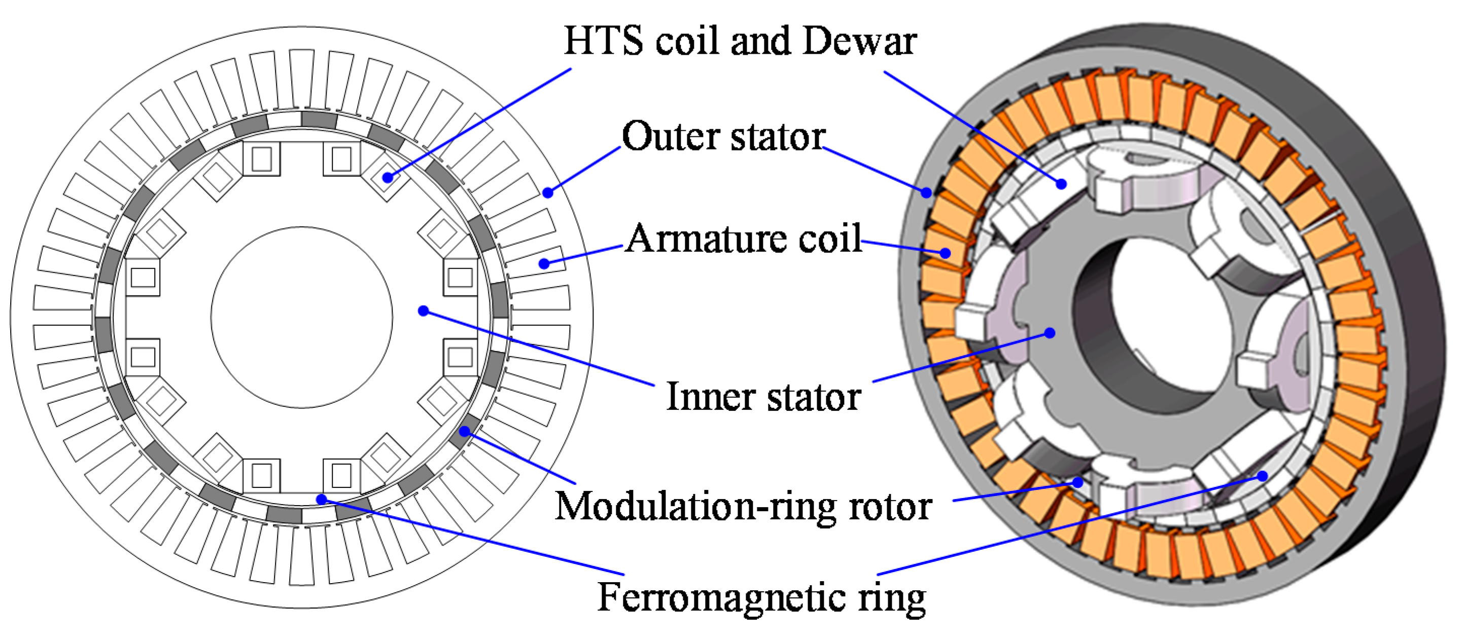
:1. Introduction
2. Analysis of Electromagnetic Force
3. Finite Element Analysis of Electromagnetic Force
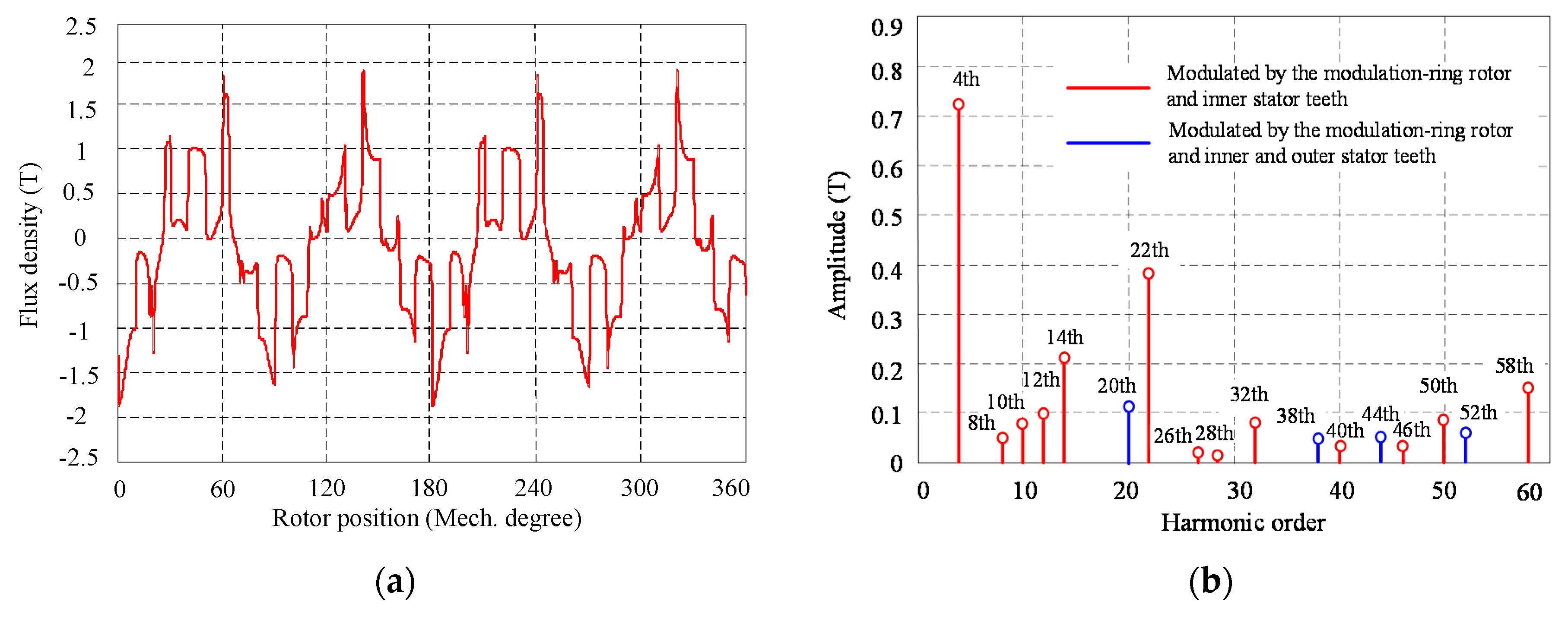
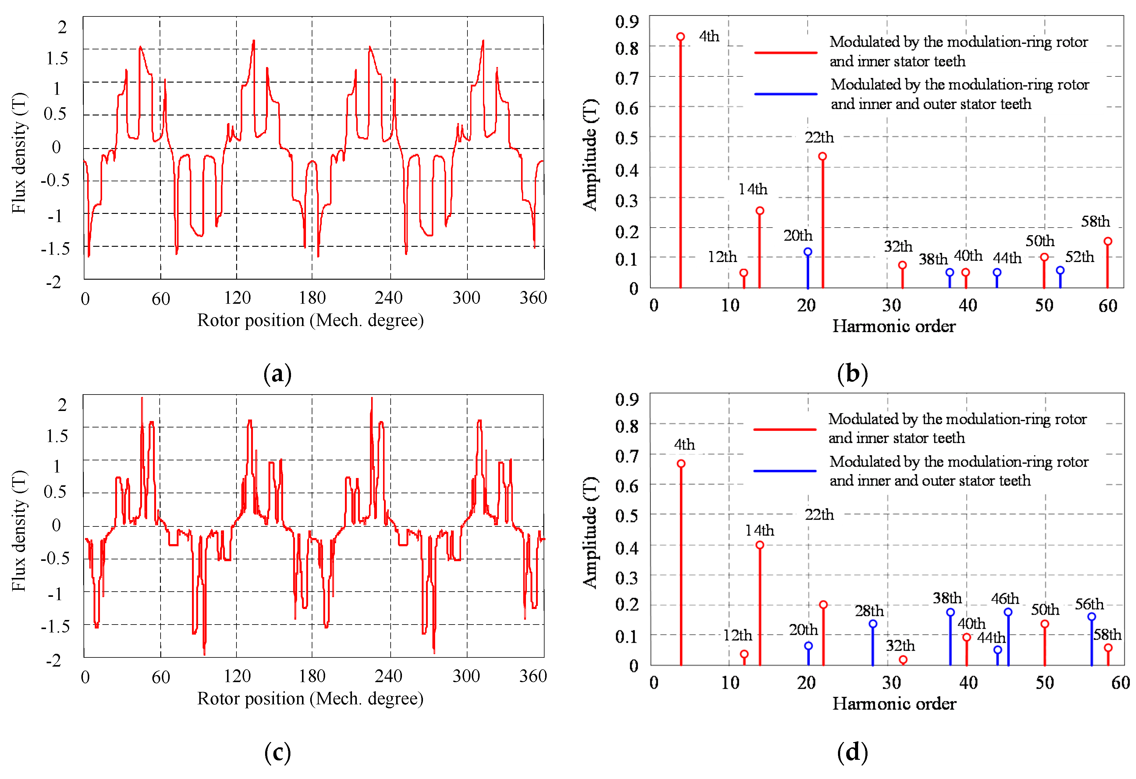
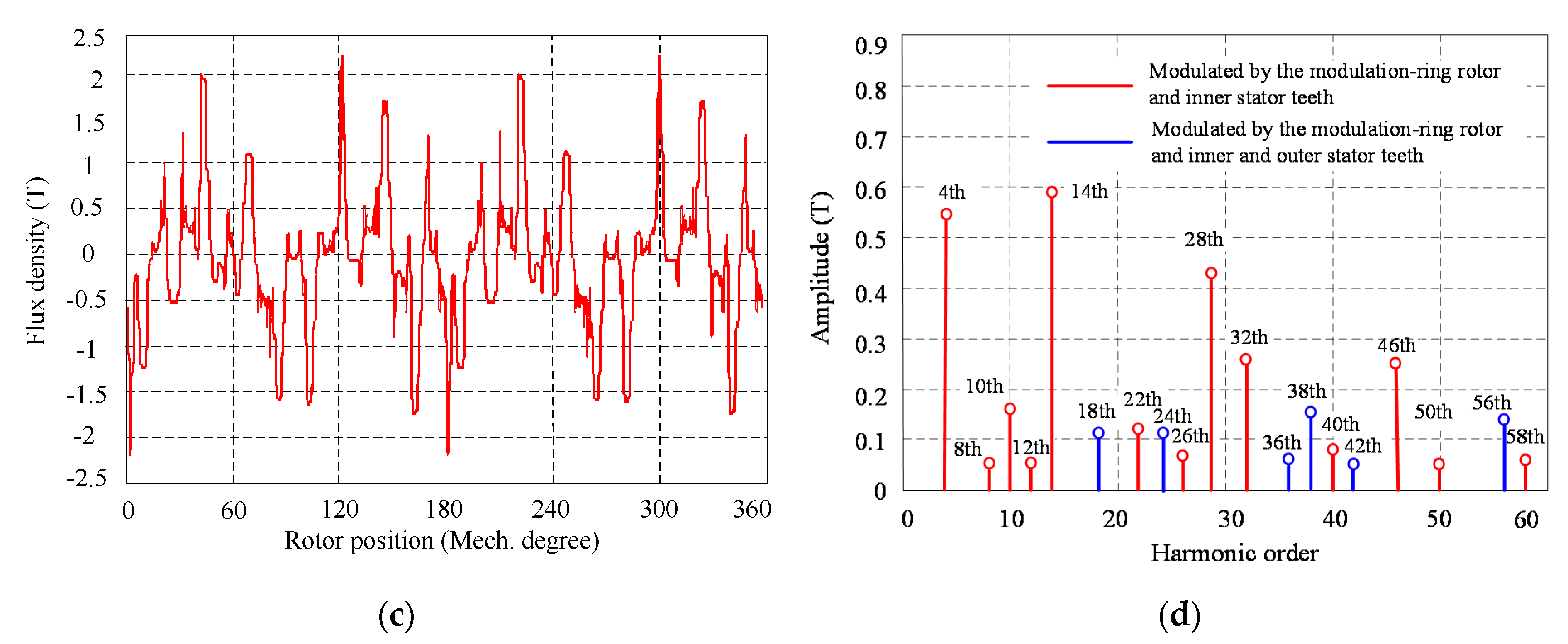
3.1. Magnetic Flux Density
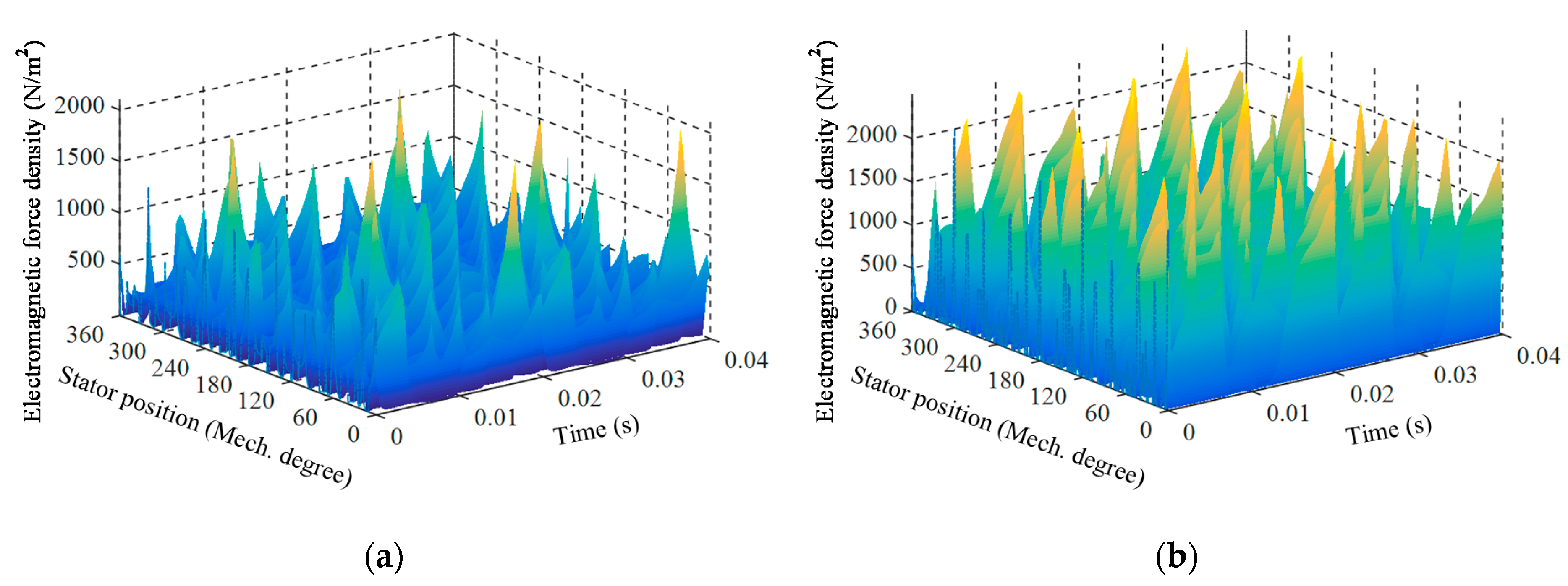
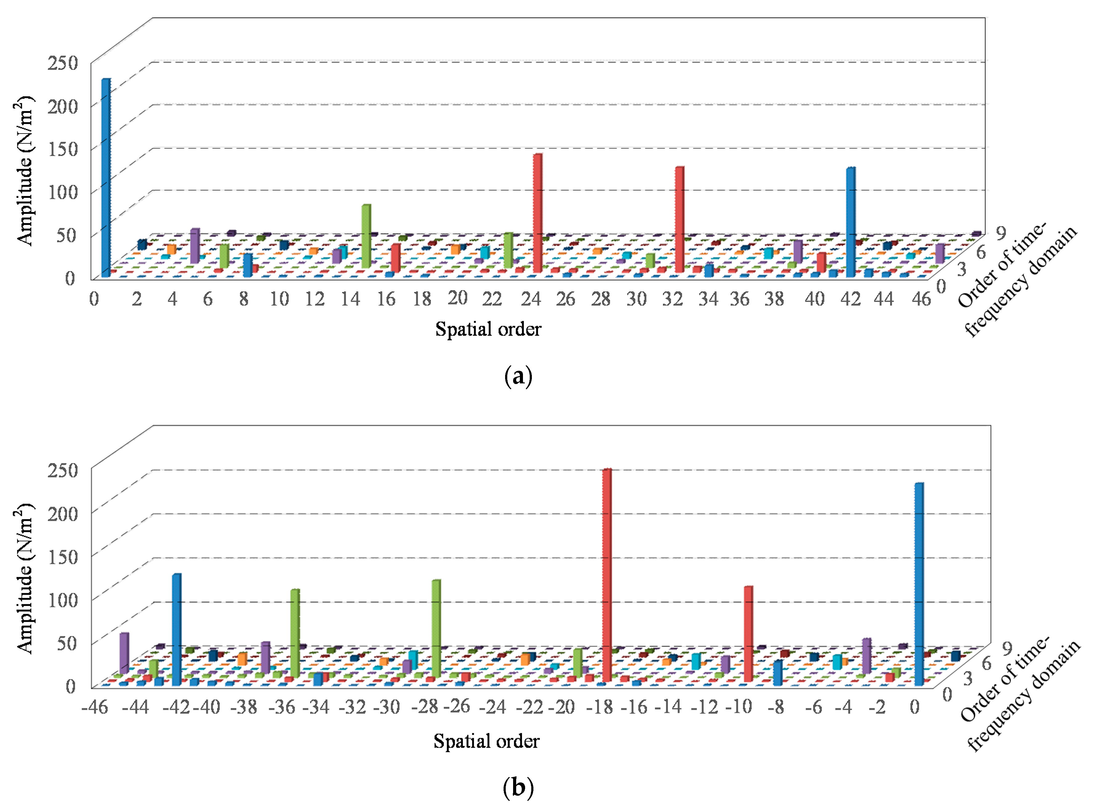
3.2. Electromagnetic Force Density
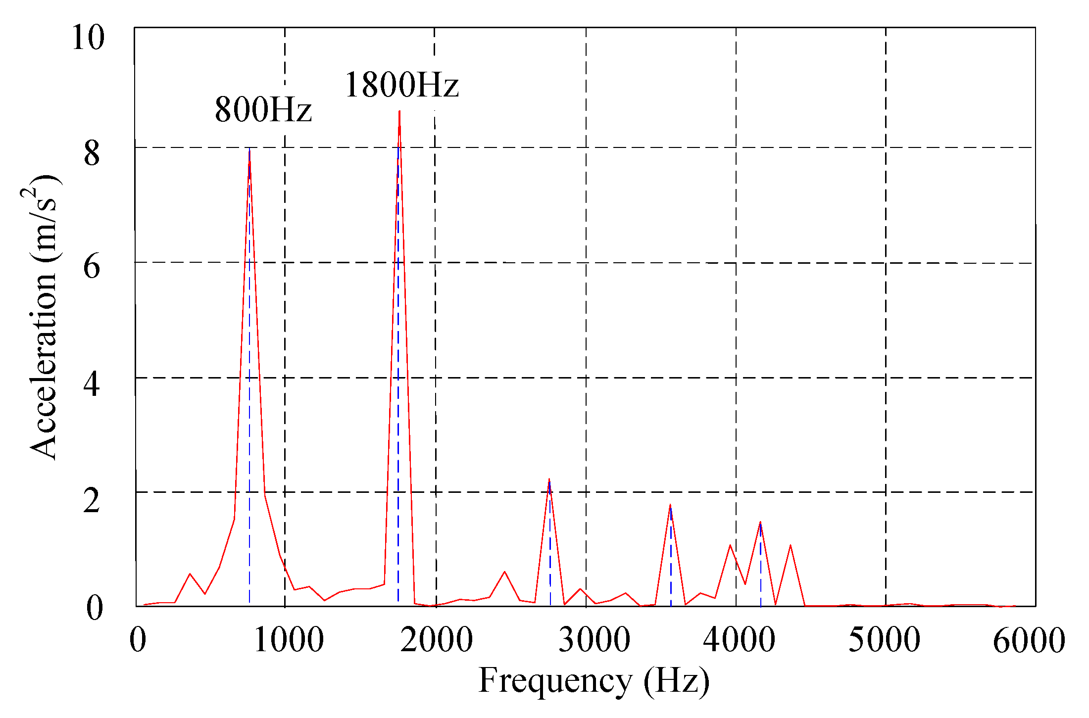
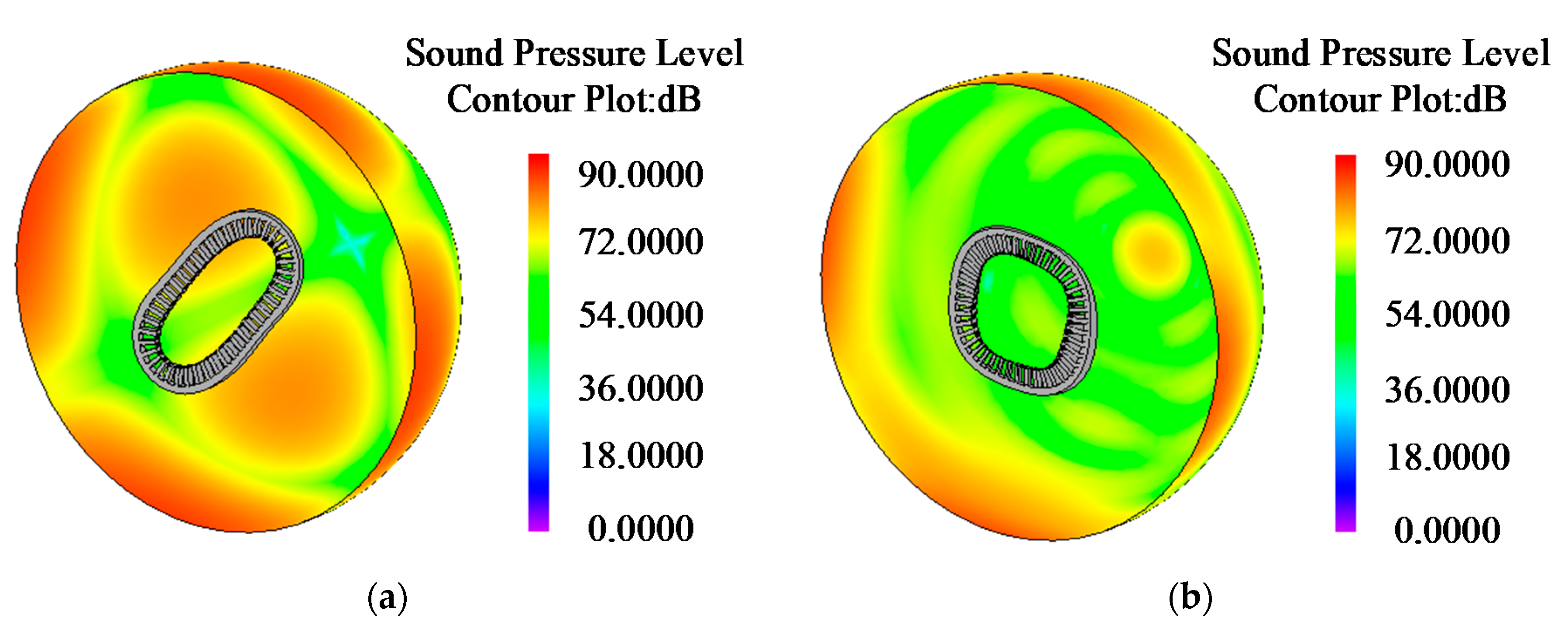
4. Structure and Vibroacoustic Analysis
5. Conclusions
Author Contributions
Funding
Conflicts of Interest
Appendix A
References
- Polinder, H.; Ferreira, J.A.; Jensen, B.B.; Abrahamsen, A.B.; Atallah, K.; McMahon, R.A. Trends in wind turbine generator systems. IEEE J. Emerg. Sel. Top. Power Electron. 2013, 1, 174–185. [Google Scholar] [CrossRef]
- Yanamoto, T.; Izumi, M.; Yokoyama, M.; Umemoto, K. Electric propulsion motor development for commercial ships in Japan. Proc. IEEE 2015, 103, 2333–2343. [Google Scholar] [CrossRef]
- Shafaie, R.; Amirkhanloo, F.; Kalantar, M. Toward an optimum design of large-scale HTS synchronous generator for wind turbine applications. IEEE Trans. Appl. Supercond. 2016, 26. [Google Scholar] [CrossRef]
- Kalsi, S.S.; Weeber, K.; Takesue, H.; Lewis, C.; Neumueller, H.W.; Blaugher, R.D. Development status of rotating machines employing superconducting field windings. Proc. IEEE 2004, 92, 1688–1704. [Google Scholar] [CrossRef]
- Klaus, G.; Wilke, M.; Frauenhofer, J.; Nick, W.; Neumuller, H.W. Design challenges and benefits of HTS synchronous machines. In Proceedings of the 2007 IEEE Power Engineering Society General Meeting, Tampa, FL, USA, 24–28 June 2007. [Google Scholar]
- Kalsi, S.S. Development status of superconducting rotating machines. In Proceedings of the 2002 IEEE Power Engineering Society Winter Meeting. Conference Proceedings, New York, NY, USA, 27–31 January 2002. [Google Scholar]
- Gamble, B.; Snitchler, G.; Kalsi, S.S. HTS generator topologies. In Proceedings of the 2006 IEEE Power Engineering Society General Meeting, Montreal, QC, Canada, 18–22 June 2006. [Google Scholar]
- Wang, Y.; Wang, C.; Feng, Q.; Li, X.; Ching, T.W. Fabrication and experiment of racetrack HTS coil for stator field-excitation HTS machine. IEEE Trans. Appl. Supercond. 2017, 27. [Google Scholar] [CrossRef]
- Wang, Y.; Wang, C.; Feng, Q.; Li, X. Design and experiment of an HTS flux-switching machine with stationary seal. IEEE Trans. Appl. Supercond. 2017, 27. [Google Scholar] [CrossRef]
- Wang, Y.; Feng, Q.; Li, X.; Ma, W. Design, analysis, and experimental test of a segmented-rotor high temperature superconducting generator with stationary seal. IEEE Trans. Ind. Electron. 2018. [Google Scholar] [CrossRef]
- Li, J.; Song, X.; Cho, Y. Comparison of 12/8 and 6/4 switched reluctance motor: Noise and vibration aspects. IEEE Trans. Magn. 2008, 44, 4131–4134. [Google Scholar] [CrossRef]
- Colby, R.S.; Mottier, F.M.; Miller, T.J.E. Vibration modes and acoustic noise in a four-phase switched reluctance motor. IEEE Trans. Ind. Appl. 1996, 32, 1357–1364. [Google Scholar] [CrossRef] [Green Version]
- Lin, C.; Fahimi, B. Prediction of acoustic noise in switched reluctance motor drives. IEEE Trans. Energy Convers. 2014, 29, 250–258. [Google Scholar] [CrossRef]
- Wu, S.; Zuo, S.; Wu, X.; Lin, F.; Zhong, H.; Zhang, Y. Vibroacoustic prediction and mechanism analysis of claw pole alternators. IEEE Trans. Ind. Electron. 2017, 64, 4463–4473. [Google Scholar] [CrossRef]
- Tan-Kim, A.; Lanfranchi, V.; Vivier, S.; Legranger, J.; Palleschi, F. Vibro-acoustic simulation and optimization of a claw-pole alternator. IEEE Trans. Ind. Appl. 2016, 52, 3878–3885. [Google Scholar] [CrossRef]
- Noda, S.; Mori, S.; Ishibashi, F.; Itomi, K. Effect of coils on natural frequencies of stator cores in small induction motors. IEEE Trans. Energy Convers. 1987, 93–99. [Google Scholar] [CrossRef]
- Besnerais, J.L.; Lanfranchi, V.; Hecquet, M.; Brochet, P. Characterization and reduction of audible magnetic noise due to PWM supply in induction machines. IEEE Trans. Ind. Electron. 2010, 57, 1288–1295. [Google Scholar] [CrossRef]
- Islam, M.S.; Islam, R.; Sebastian, T. Noise and vibration characteristics of permanent-magnet synchronous motors using electromagnetic and structural analyses. IEEE Trans. Ind. Appl. 2014, 50, 3214–3222. [Google Scholar] [CrossRef]
- Fang, Y.; Zhang, T. Vibroacoustic characterization of a permanent magnet synchronous motor powertrain for electric vehicles. IEEE Trans. Energy Convers. 2018, 33, 272–280. [Google Scholar] [CrossRef]
- Wang, Y.; Yang, G.; Zhu, X.; Li, X.; Ma, W. Electromagnetic Characteristics Analysis of a High-Temperature Superconducting Field-Modulation Double-Stator Machine with Stationary Seal. Energies 2018, 11, 1269. [Google Scholar] [CrossRef]
- Cheng, M.; Han, P.; Hua, W. General airgap field modulation theory for electrical machines. IEEE Trans. Ind. Electron. 2017, 64, 6063–6074. [Google Scholar] [CrossRef]
- Xiang, Z.; Zhu, X.; Quan, L.; Du, Y.; Zhang, C.; Fan, D. Multilevel design optimization and operation of a brushless double mechanical port flux-switching permanent-magnet motor. IEEE Trans. Ind. Electron. 2016, 63, 6042–6054. [Google Scholar] [CrossRef]
- Zheng, P.; Song, Z.Y.; Bai, J.G.; Tong, C.D.; Yu, B. Research on an axial magnetic-field-modulated brushless double rotor machine. Energies 2013, 6, 4799–4829. [Google Scholar] [CrossRef]
- Wang, Q.; Niu, S.; Yang, L. Design optimization and comparative study of novel dual-PM excited machines. IEEE Trans. Ind. Electron. 2017, 64, 9924–9933. [Google Scholar] [CrossRef]
- Wu, Z.Z.; Zhu, Z.Q. Analysis of air-gap field modulation and magnetic gearing effects in switched flux permanent magnet machines. IEEE Trans. Magn. 2015, 51, 1–12. [Google Scholar] [CrossRef]
- Du, Y.; Xiao, F.; Hua, W.; Zhu, X.; Cheng, M.; Quan, L.; Chau, K.T. Comparison of flux-switching pm motors with different winding configurations using magnetic gearing principle. IEEE Trans. Magn. 2016, 52. [Google Scholar] [CrossRef]
- Zhu, X.; Fan, D.; Mo, L.; Chen, Y.; Quan, L. Multi-objective optimization design of double-rotor flux-switching permanent magnet machine considering multi-Mode operation. IEEE Trans. Ind. Electron. 2018, 66, 641–653. [Google Scholar] [CrossRef]


| Source | Spatial Order | Angular Velocity |
|---|---|---|
| Harmonic components of excitation field | 0 | |
| Harmonic components of armature-reaction magnetic field | ||
| Interaction between the harmonic components of armature-reaction magnetic field and excitation field | ||
| Parameters | Value |
|---|---|
| Number of outer stator teeth | 42 |
| Number of inner stator teeth | 8 |
| Number of pole pairs of armature windings | 14 |
| Number of pole pairs of field-excitation windings | 4 |
| Number of modulation-ring rotor teeth | 18 |
| Stator outside diameter of outer stator (mm) | 760 |
| Stator inside diameter of outer stator (mm) | 546.4 |
| Stator outside diameter of inner stator (mm) | 504 |
| Stator inside diameter of inner stator (mm) | 240 |
| Rotor outside diameter (mm) | 42 |
| Stack length (mm) | 100 |
| Inner air-gap length (mm) | 0.6 |
| Outer air-gap length (mm) | 0.6 |
| Number of phases | 3 |
| Material Parameters | Young’s Modulus | Shear Modulus | Poisson’s Ratio | Density (kg/m3) |
|---|---|---|---|---|
| Stator core | Ex = Ey = 0.94Ew Ez = Ew | Gxy = 0.84Gw Gyz = Gzx = 0.17Gw | 0.3 | 7488 |
| Armature winding | Ex = Ey = 0.92Ec Ez = Ec | Gxy = 0.01Gc Gyz = Gzx = 0.02Gc | 0.3 | 5340 |
| Mode Number | Mode Shapes | Natural Frequencies |
|---|---|---|
| (2, 0) |  | 700.58 Hz |
| (2, 1) |  | 1127.00 Hz |
| (3, 0) |  | 1197.71 Hz |
| (3, 1) |  | 1324.22 Hz |
| (4, 0) |  | 1776.42 Hz |
| (4, 1) |  | 1644.37 Hz |
| (5, 1) |  | 1883.20 Hz |
| (6, 1) |  | 2148.16 Hz |
| (7, 1) |  | 2382.76 Hz |
| (8, 1) |  | 2587.80 Hz |
© 2018 by the authors. Licensee MDPI, Basel, Switzerland. This article is an open access article distributed under the terms and conditions of the Creative Commons Attribution (CC BY) license (http://creativecommons.org/licenses/by/4.0/).
Share and Cite
Wang, Y.; Zhao, C.; Xu, W.; Zhang, X. Vibroacoustic Prediction of a High-Temperature Superconducting Field-Modulation Double-Stator Machine with Stationary Seal. Energies 2018, 11, 2563. https://doi.org/10.3390/en11102563
Wang Y, Zhao C, Xu W, Zhang X. Vibroacoustic Prediction of a High-Temperature Superconducting Field-Modulation Double-Stator Machine with Stationary Seal. Energies. 2018; 11(10):2563. https://doi.org/10.3390/en11102563
Chicago/Turabian StyleWang, Yubin, Chenchen Zhao, Wei Xu, and Xiaodong Zhang. 2018. "Vibroacoustic Prediction of a High-Temperature Superconducting Field-Modulation Double-Stator Machine with Stationary Seal" Energies 11, no. 10: 2563. https://doi.org/10.3390/en11102563
APA StyleWang, Y., Zhao, C., Xu, W., & Zhang, X. (2018). Vibroacoustic Prediction of a High-Temperature Superconducting Field-Modulation Double-Stator Machine with Stationary Seal. Energies, 11(10), 2563. https://doi.org/10.3390/en11102563