Article

Development of Numerical Heat Transfer and the Structural Model to Design Slim and Translucent Vacuum Layer Type Insulation Panels to Retrofitting Insulation in Existing Buildings

Division of Human Environmental Systems, Graduate School of Engineering, Hokkaido University, N13-W8, Kita-ku, Sapporo 060-8628, Japan
*
Author to whom correspondence should be addressed.
Energies 2017, 10(12), 2108; https://doi.org/10.3390/en10122108
Submission received: 3 November 2017 / Revised: 6 December 2017 / Accepted: 8 December 2017 / Published: 11 December 2017

Abstract

:
The authors develop slim and light-weight vacuum insulation panels (VIPs) by producing vacuum layers with spacers and plastic plates. The developed VIPs have the advantages of a low cost and easy installation, thus facilitating retrofitting insulation of existing buildings. In addition, one of the developed VIPs is slim and translucent so it can be easily used for windows in an internal installation. In this paper, the authors first propose a vacuum layer type slim translucent VIP and focus on a reasonable design method. Next, the authors introduce the design process in which the structural design is obtained with element mechanical analysis and a three-dimensional analysis is conducted for the VIP element. In the study, a heat transfer model is used to predict the insulation performance through finite element analysis (FEA). Subsequently, the authors perform an experiment to measure the thermal conductivity in a guarded hot plate apparatus to validate the performance prediction. Finally, case studies are performed to confirm how the different design conditions affect the insulation performance. The optimum design of the vacuum layer type slim and translucent VIP will have a sufficient structural strength to hold and maintain the vacuum layer. The thermal conductivity is approximately 0.007 W / ( m · K ) , which can effectively improve the insulation performance in applications.

1. Introduction

Environmental problems and energy exhaustion have become major global issues. The annual energy consumption has been increasing every year, and the amount of environmental pollution is accelerating. Building energy use is the largest contributor to energy consumption, accounting for up to 45% of the total energy consumption worldwide [1]. Thus, various technologies, such as heat pumps and heat recovery ventilation, have begun to be applied to reduce building energy consumption [2]. Numerous energy-saving technologies for building applications are installed in new buildings. However, these technologies are useless if installed in existing buildings in which the thermal insulation performance, in particular, is poor. Therefore, it is important to improve their insulation performance. Using conventional insulators for achieving high-level thermal insulation requires an extremely large volume of insulation materials. Vacuum insulation panels (VIPs) have a thermal resistance that is approximately 10 times higher than that of equally thick conventional polystyrene boards, and the insulation performance if applied VIPs has been investigated in some studies (Taesub Lim 2017; Alfonso Capozzoli 2015; Seung-Yeong Song 2014) [3,4,5].
Most models of conventional VIPs include a core material with a low-thermal conductivity coating of a gas barrier film (in particular, aluminum foil), and they are always used in refrigerators and thermoses. In current good building practices, windows are considerably less well-insulating than other parts of a structural envelope. The necessity to reduce energy consumption requires a greater use of smaller windows than may be architecturally or aesthetically desirable, which in turn reduces the potential for solar gain in cold climates. Therefore, the study of vacuum insulation technology that is applied to buildings has been performed since the 1990s. A representative study of the vacuum insulation technology is the study of vacuum glazing by R. E. Collins [6,7,8,9,10,11,12]. In the corresponding research, pillars are used between two pieces of glasses to form a vacuum layer, and a low emissivity (low-e) film is employed to reduce the thermal emissivity, which is approximately 0.9 for glass [6]. Then, the durability of the pillars is investigated and their influence is discussed [7]. The cost to produce the vacuum glazing is compared with a model in which argon is filled in a pair glass with a low-e film, and the result shows a 25% increase in the cost.
The study of the application of VIPs to buildings as panels and sheets is gaining prominence worldwide. An aluminum vapor deposited Polyethylene terephthalate (PET) film is used as a core material for analysis (this is called the core material of metallic multilayer and fiber overlapping [13]); however, it is yet to be manufactured [14]. Analysis of the heat transfer model of nanoporous silica vacuum insulation material is proposed by Bouquerel [15]. Kwon examined the powder, foam, and fiber type models, followed by the heat transfer model of the core material with a staggered beam. Finally, the fiber type model of the staggered beam core material was found to be effective [16]. In addition, Johansson proposed a short-term in-situ performance measurement method for VIPs, and its accuracy is being verified [17].
The guarded hot plate (GHP) method is considered because it is a satisfactory method for measuring very low thermal conductivities [18]. In particular, a vacuum GHP (VGHP) apparatus is manufactured to eliminate the residual gas conduction. A VGHP can maintain a high vacuum level (below 10−4 Pa), leading to the effective measurement of thermal conductivities.
Of late, various energy-saving techniques are being employed in new buildings; however, these techniques are difficult to apply to existing buildings. In particular, the thermal insulation performance is poor, hence it is important to improve the insulation performance. The VIP has the potential to improve the insulation performance effectively. However, the conventional VIPs have some issues in terms of their applications, such as: an expensive cost due to a complicated manufacturing process; low durability; the possibility of fatal damage due to nailing; and the influence of the thermal bridge. Furthermore, there are no commercially-available translucent VIPs that can be applied to windows with lower insulation performances. Therefore, it would be more effective to develop the slim and translucent vacuum insulation panel and install it in existing buildings. The authors developed a new model of a VIP that is thin and translucent, can be easily installed, and assists with retrofitting insulation in existing buildings, even including the windows, as illustrated in Figure 1. This proposal will have a good resistance to degradation from the weather effect due to the internal installation. This VIP model consisted of two plates with a low-e film coating achieved using a gas barrier film, while the vacuum layer was supported by plastic spacers. With respect to the durability, if the VIPs are easy to install, the degraded ones can be replaced by new ones, owing to the highly cost-effective core material. In terms of the cost, simplification in the production of VIPs with slim and flat core material can be expected in the preparation stage. In this paper, the heat transfer calculation model for the above VIP is described and the calculation conditions are summarized to determine how strongly the conditions affect the insulation performance of VIPs. The calculated results are summarized and compared. Subsequently, in the study, an experiment is conducted to measure the heat flux of the VIP samples and the results are compared with the calculated results. Finally, the insulation performance of the proposed VIP is discussed. In the study, finite element analysis (FEA) is applied for predicting the heat transfer coefficient and thermal transmittance of the VIP under different conditions. A comparison of the insulation performance of the VIP with the different conditions is presented, and a standard calculation model is considered as the representative reference object for comparison.

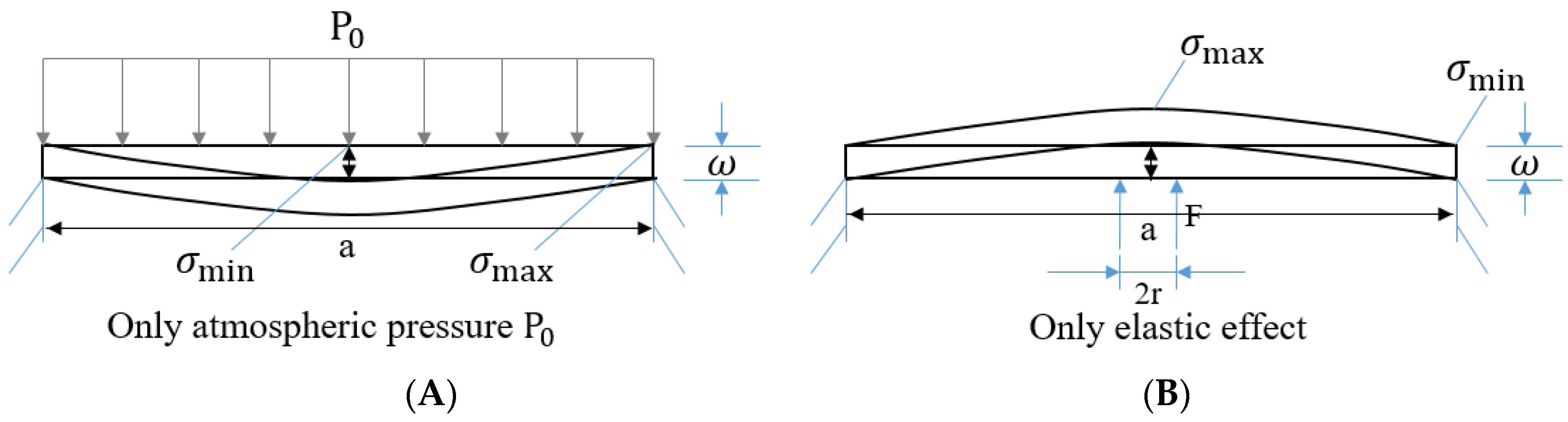
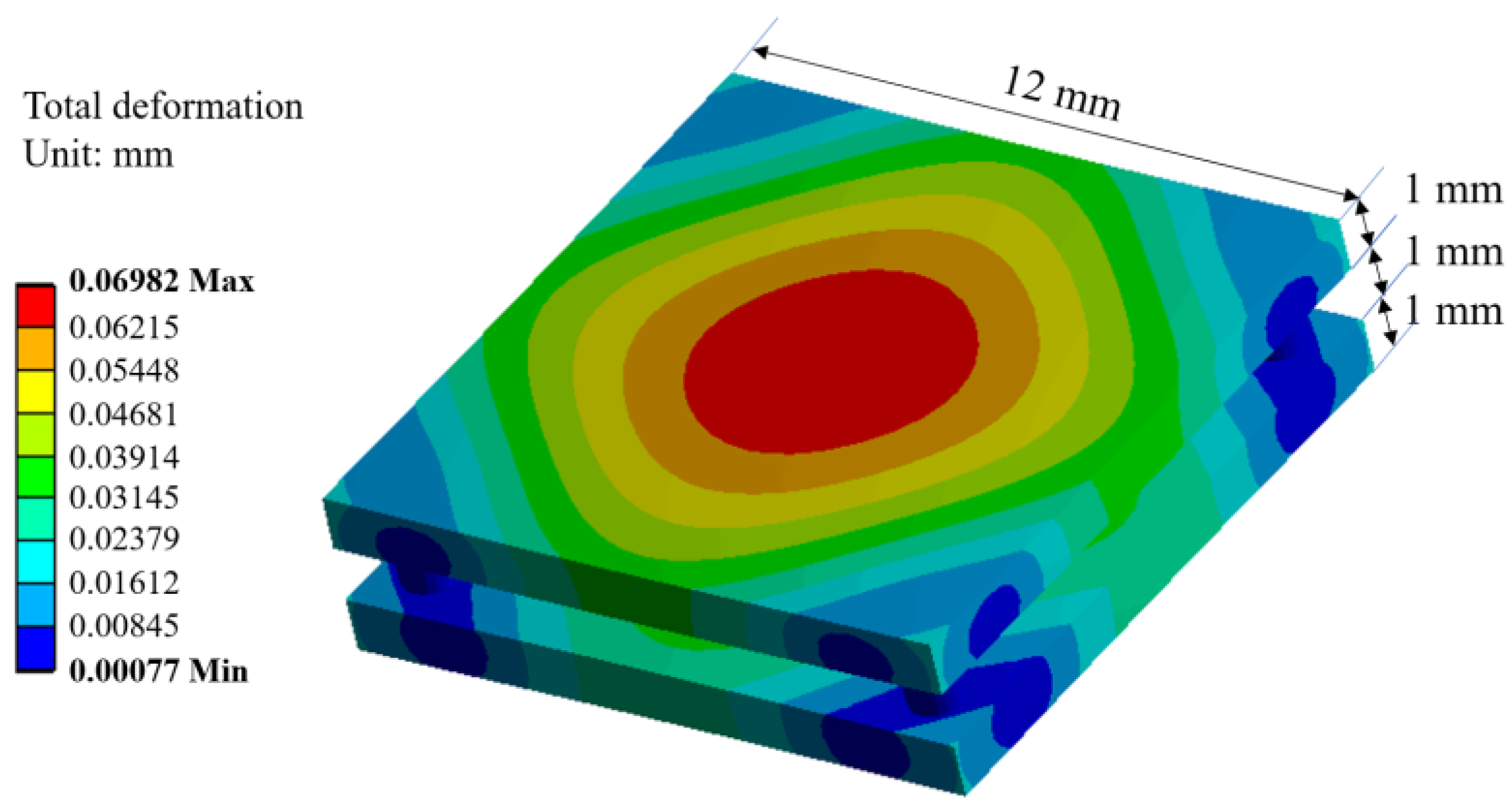
2. Mechanical Analysis and Core Structural Design for Vacuum Layer Type Slim and Translucent VIP

In this section, to determine the reasonable size of the VIP design, the authors discussed the stress analysis and the calculated maximum deflection. If the loading condition applied to the panel in the form of a distributed air compression is the same throughout, as shown in Figure 2A, mechanical analysis as depicted in Figure 2B [19,20] will have to be conducted. The structural calculation model can be applied for calculating two possibilities, and Figure 3 shows the schematic of the calculation model.
In this calculation model, when the effective load is applied only through atmospheric pressure, maximum stress occurs in the center of the plate, whereas the minimum stress is on the edge. However, when only the elastic effect is present, the scenario is opposite to the above case, and hence, the stress direction is the reverse of the overall mechanical analysis. In this section, we define the relationship between the deflection and span (between the two spacer supports) by using the equations provided below.
ω ¯ m a x = δ × P 0 × a 4 D
D = E d p 3 12 ( 1 μ 2 )
For the acrylic plate, here, E is the elasticity modulus (= 3.2 GPa) and μ is the Poisson’s ratio (= 0.35). In this model, the thickness of the acrylic plate d p = 1 mm, span a = 1 mm, δ 1 = 0.0138 (coefficient when the rectangular flat plate is functioned by a uniform load), δ 2 = 0.0611 (coefficient when the rectangular flat plate is functioned by a uniform load) and the effect in different stresses, and P 0 = 1013 hPa. Figure 4 shows the maximum deflection of the acrylic plate (both sides: the front and back) with the spacers in different spans.
Figure 4 indicates that every designable load element can hold the vacuum layer within the safety margin requirement for a mechanical design. To obtain and hold the vacuum layer, the authors decided that the span of the spacers would be 10 mm. There is an overall consideration of the stress effect and safety margin to ensure the application of the heat transfer model and specimen in the trial manufacture for the experiment. The result ensures not only the formation of a vacuum layer, but also that the surface can be kept relatively flat.
Subsequently, to confirm the structural design, the authors also generate a 3-D model using the simulation software, “ANSYS workbench” (14.0, ANSYS, Canonsburg, PA, USA). The fixed boundary condition indicates that the element analysis is reasonable for a full-size VIP and the meshing in Figure 5 shows that the calculation result is fairly accurate due to the total of 14,039 nodes and 2808 elements. The distribution of the total deformation for the VIP element that is modelled in Figure 2B is shown in Figure 6. The result can validate the mechanical analysis, indicating that the structural design is strong enough to keep the vacuum layer sufficiently flat for the application.

3. Framework of Heat Transfer Calculation Model

The analytical solution of the heat transfer through a VIP can be derived from a double plate unit [21]. Figure 7 illustrates the heat transfer through a double plate unit. The overall heat transfer coefficient can be obtained according to this model. The heat transmittance of the VIP can ignore the convection in the vacuum space, and this will be explained in the following part.

3.1. Calculation and Design of the Vacuum Layer

At a constant pressure or at the vacuum state, the mass and density will be different in each part owing to the inhomogeneous temperature distribution. The parts differing in density will have a relative motion affected by the same gravity, and the heat transmission occurs through the motion. Along with the different vacuums, different fluids and flow states, shapes of the heat transfer surface, and different positions of the hot and cold surface, the power of the free convective heat transfer will also be different. Numerous experimental studies show that the free convection can be converted into pure gas heat conduction. When the equation below is established, the free convection can be converted into pure gas heat conduction.
G r m × P r m < 10 3
Here, P r m is the Prandtl number. For air, nitrogen, and helium, P r m = 0.7. G r m is the Grashof number.
G r m = g β Δ T L v 3 υ 2
Here, g is the gravity acceleration ( m / s 2 ), β is the coefficient of expansion (1/K), and β can be described by the following equation [22].
β = 1 γ ( V T ) P b 2
Here, P b is the pressure ratio, such that P b = P / P 0 ; P is the vacuum pressure, (Pa); P 0 is the atmospheric pressure, (Pa); Δ T is the temperature difference between the cold and hot surface, ( K ); L v is the thickness of the vacuum layer, ( m ); and   υ is the kinematic viscosity, ( m 2 / s ). Here, = 9.8 m / s 2 , L v = 10 3 m, Δ T = 25 K, υ = 1.323 × 10 5 m 2 / s , and the assumed value of vacuum pressure P = 1000 Pa.
Therefore, G r m 2.085 × 10 6 ( 10 3 10 5 ) 2 = 2.085 × 10 2 < 10 3 , and this result shows that convection can transform into pure gas conduction in this model if the pressure is less than 1000 Pa.
To achieve a lower thermal conductivity, the VIP with a vacuum layer between 0.1 Pa and 1 Pa will be calculated under the conditions. For a pressure of 0.1 Pa and 1 Pa, the convection can convert to pure gas conduction naturally, and therefore, the convection can be ignored in the calculation.
Generally, for the analysis of the heat conduction of gases in an adiabatic space, the evaluation behavior to separate the air flow is defined by using the Knudsen Number K n . A high Knudsen number indicates a low pressure, and thus a slow molecular flow, whereas a low value of the Knudsen number suggests a viscous flow. Then, the rarefied gas heat conduction in the different states can be decided by evaluating the Knudsen number as defined in Equations (6) and (7) [23].
K n = l L v
l = k T 2 π d 2 P
Here, l is the mean free path of air, (m); L v is the thickness of the vacuum layer, (m); k is the Boltzmann constant, (J/K); T is the temperature, (K); d is the molecular diameter, (m); and   P is the pressure, (Pa).
In this paper, temperature T = 300   ( K ) , k = 1.38 × 10 23 J/K, and molecular diameter d = 0.37   nm . Then, Equation (7) can be expressed as l = 6.8 × 10 3 / P . The assumed thickness of the vacuum layer L v = 1 mm; therefore, the Knudsen number is 68, 6.8, and 0.68 when the pressure is 0.1 Pa, 1 Pa, and 10 Pa, respectively. If the Knudsen number K n 0.5 , only then will the rarefied gas heat conduction be in the free molecular state. Then, the calculation of the vacuum layer can be decided, and the detailed equations will be discussed in the next section.

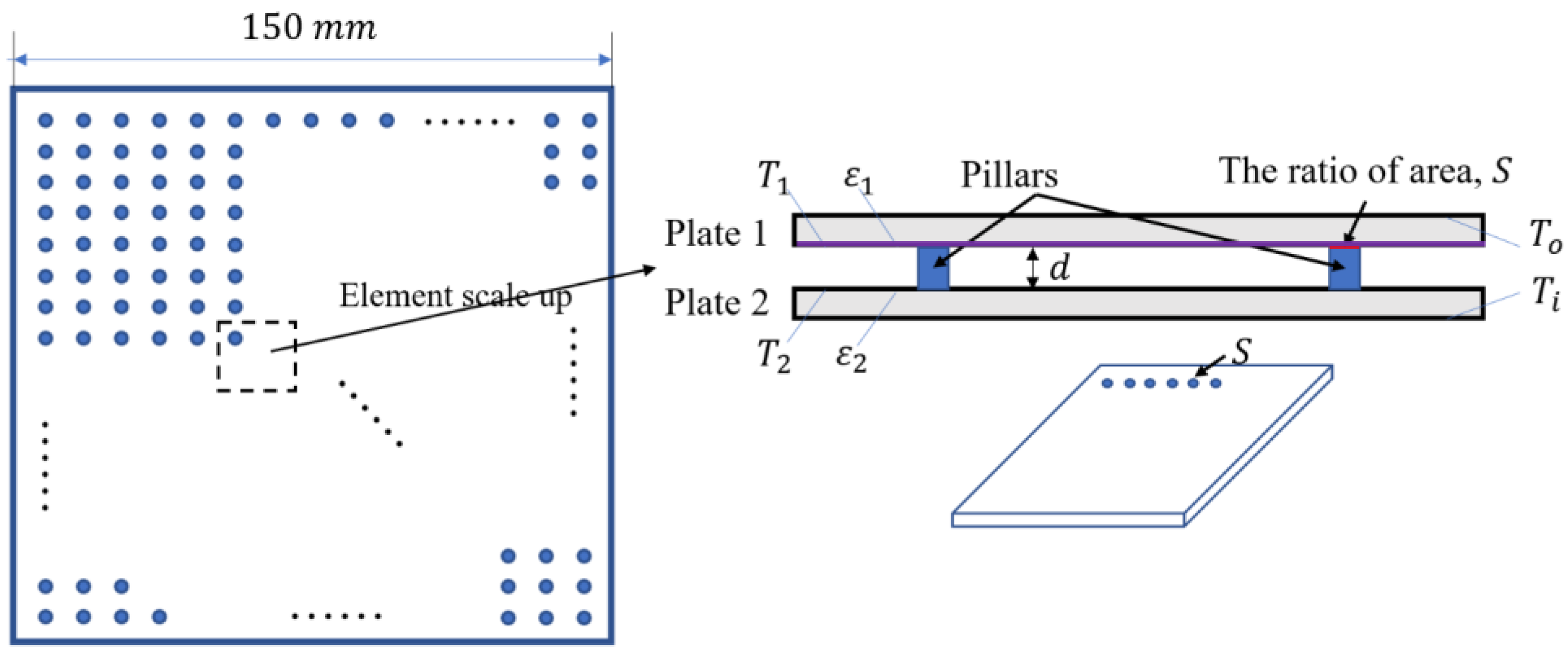
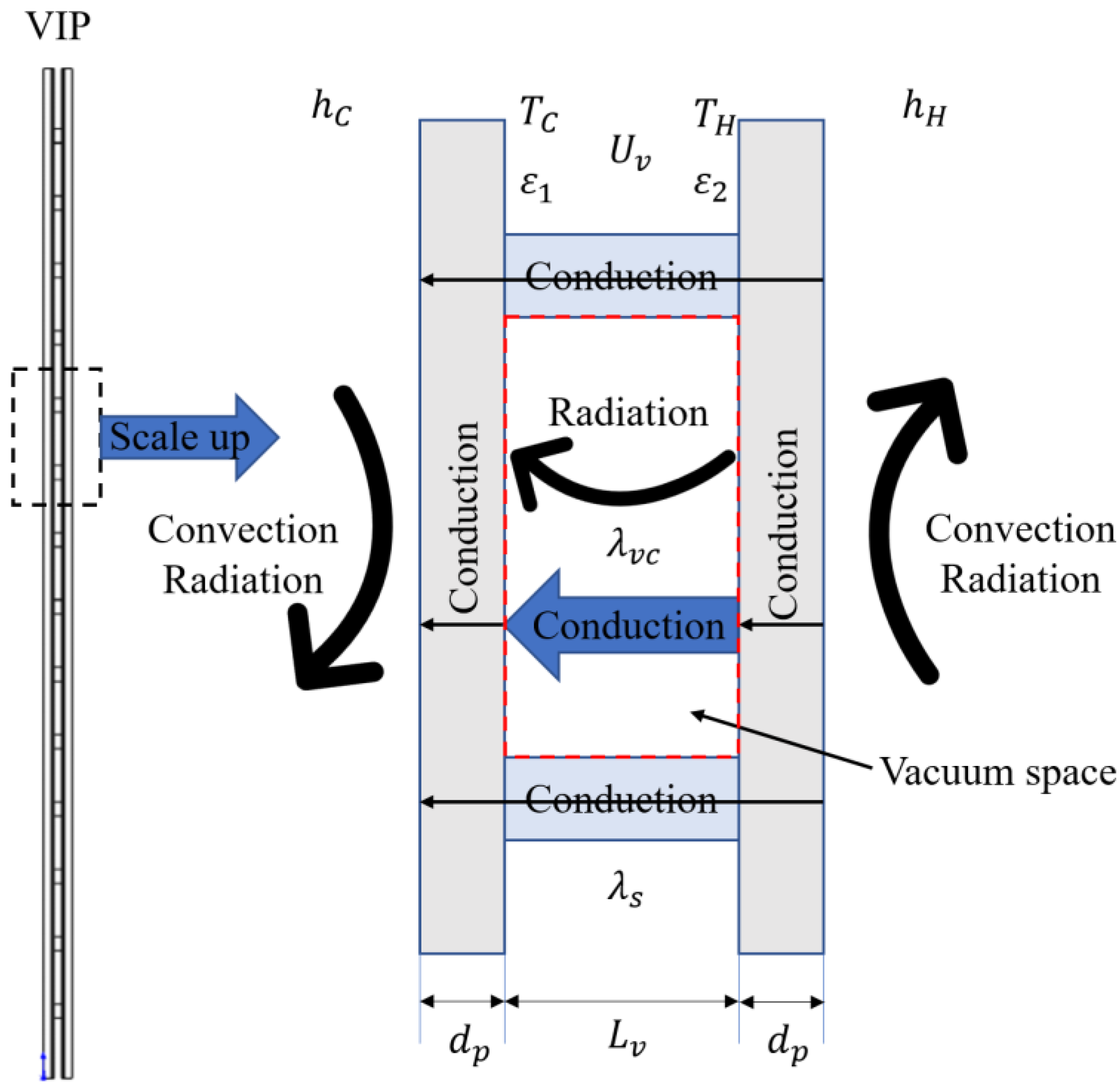
3.2. Establishment of Heat Transfer Calculation Model

The overall heat transfer coefficient of a VIP is defined by the following equation [22,23,24]:
U = 1 R C + C T + R H
Here, U is the overall heat transfer coefficient ( W / ( m 2 · K ) ); R C and R H are the thermal resistances of the cool temperature and hot temperature sides ( ( m 2 · K ) / W ) , respectively; and C T is the conductance of the vacuum insulation panel unit ( W / ( m 2 · K ) ).
C T = 1 U v + 2 d p λ p
Here, U v is the overall heat transfer coefficient between a vacuum space ( W / ( m 2 · K ) ), d p is the total thickness of the acrylic plate (m), and λ p is the thermal conductivity of the acrylic plate ( W / ( m 2 · K ) ). The value of U v is calculated based on two parts, namely, the heat transfer in the vacuum space and in the spacers.
U v = 1 R v c + R v r
Here, R v c and R v r are the thermal resistances of the conduction and radiation in the vacuum space ( W / ( m 2 · K ) ), respectively. In the vacuum space, the total heat transfer can be calculated by conduction and radiation.
2 T x 2 + 2 T y 2 + 2 T z 2 = 0
Conduction can be calculated by the above equation, and it is considered that the heat transfer in the spacer is only the conductive heat transfer. The equation is the same as the equation above. In this calculation, the thermal conductivity of the vacuum space λ v is a constant, and the thermal conductivity of the vacuum layer λ v is calculated by the equation below:
λ v = 18.2 L v γ + 1 γ 1 β 0 P M T
1 T 2 T 1 + T 2
Here, γ is the specific heat ratio, Cp/Cv is specific heat ratio, and β 0 is the accommodation coefficient. The radiant heat transfer in the vacuum space is calculated by the equations below:
R v r = 1 h v r
h v r = σ T m 3 ( ε 1 ε 2 ) φ 1 , 2
Here, σ is the Stefan–Boltzmann constant 5.67 × 10 8   W / ( m 2 K 4 ), ε 1   and   ε 2 are the corrected emissivities of the two plates of the VIP at mean temperature T m (K), and φ 1 , 2 is the angle factor between the two plates of the VIP and can be calculated by the following equation:
φ 1 , 2 = 1 A 2 A 1 A 2 cos θ 1 cos θ 2 π r 2 δ 12 d A 1 d A 2
Here, δ 12 is determined by the visibility of d A 2 to d A 1 ; δ 12 = 1 if d A 2 is visible to d A 1 and is 0 otherwise.

4. Validation of Numerical Model by Comparison with Experimental Results

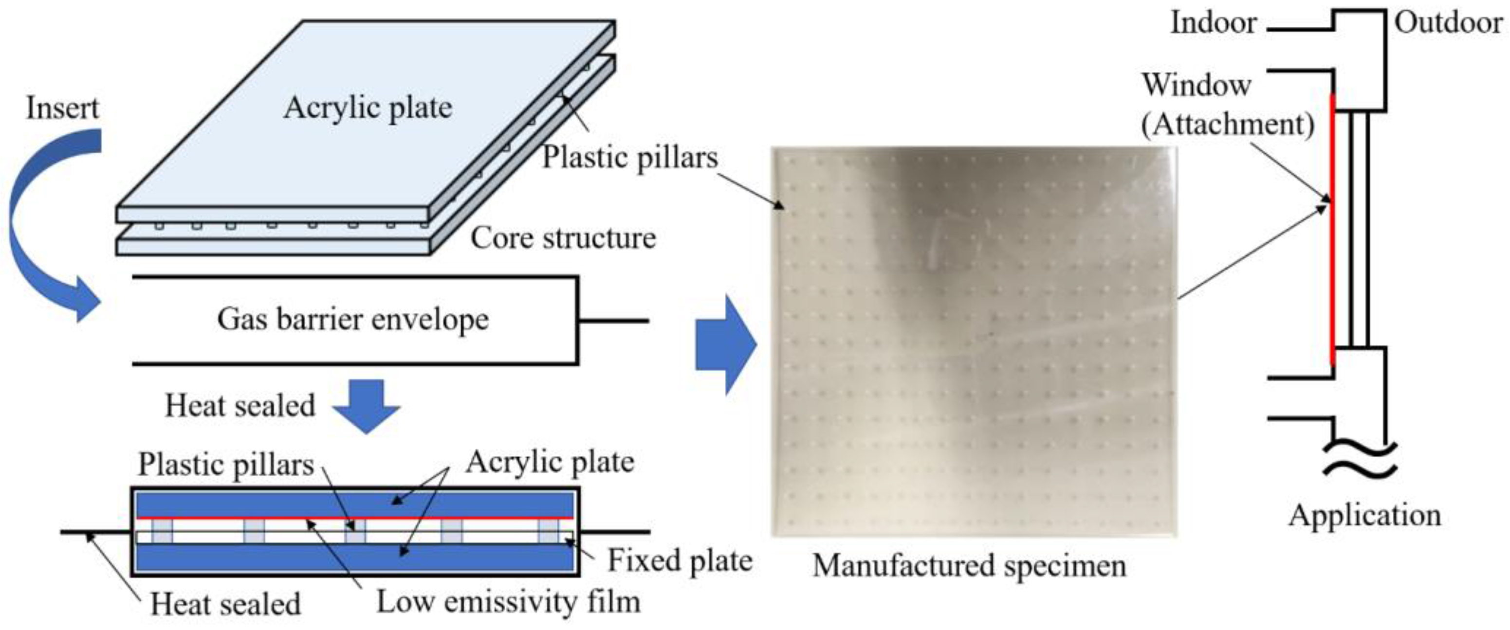
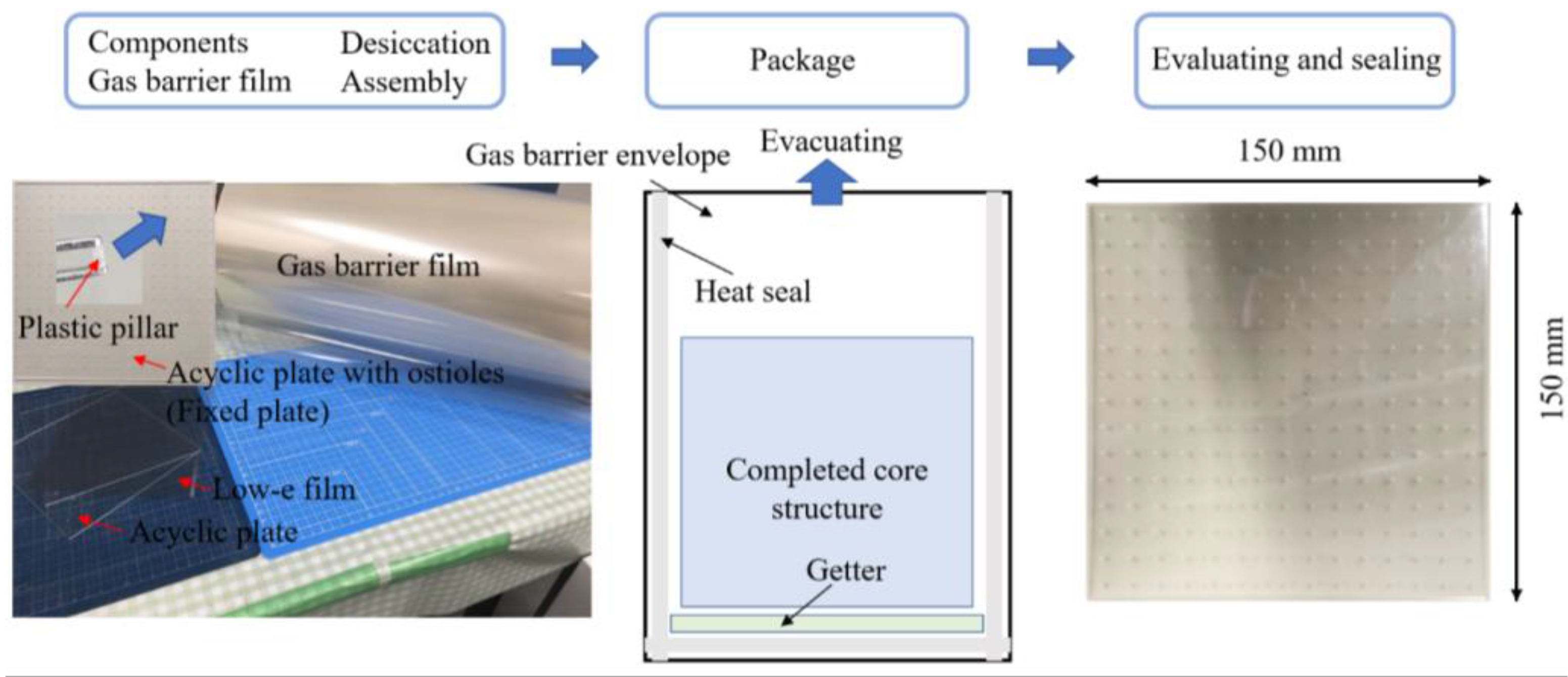
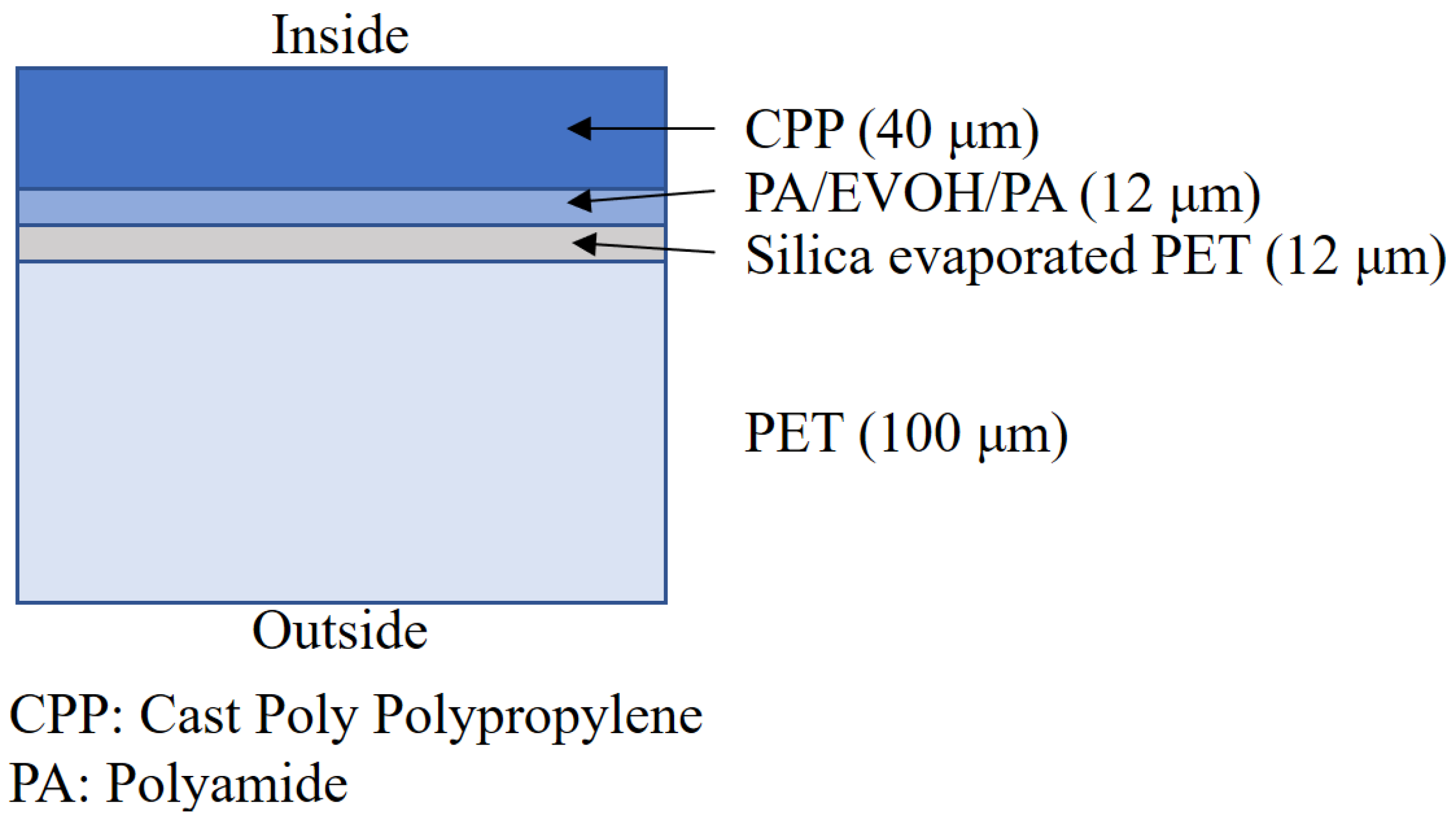
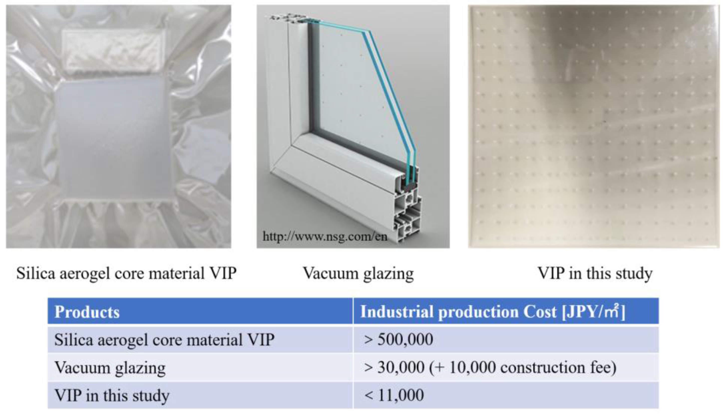
4.1. VIP Production and its Cost Performance Evaluation

The VIP test specimen is produced as per the flow in Figure 8. The components are installed in a core structure initially and a low-e film covers the surface of the core structure, which is then inserted into a transparent gas barrier envelope. In order to prevent degradation with time, a calcium oxide getter is sealed together with the core material. The getter absorbs gas and effectively prevents performance degradation. For the evacuated insulation material, the air tightness is critical and the components of the gas barrier film are depicted in Figure 9. There are three reasonable transparent evacuated insulation products: silica aerogel core material VIP, vacuum glazing, and the VIP we developed. In keeping with the economic considerations of retrofitting insulation to existing buildings, a reasonable product also requires a good cost-performance; Figure 10 shows the comparison of the industrial manufacture cost of these three insulation products. Silica aerogel core material VIP here is our experimental batch, not a commercial product; however, the cost of silica aerogel is very expensive. The NSG-group is the most famous vacuum glazing supplier, and the cost of vacuum glazing can be seen on their website in Figure 10.

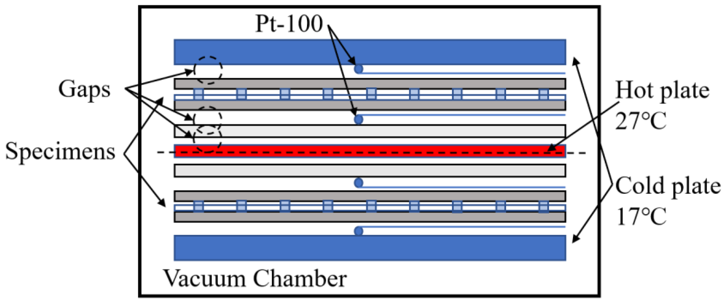
4.2. Framework of Guarded Hot Plate Apparatus

The measurement tools allow the determination of the thermal conductivity and thermal resistance of homogeneous plates and inhomogeneous test specimens, if the specimens are plane- and plate-shaped. The test specimens are installed between the heating and cooling plates. A constant heat flow flows through the test specimens in the stationary temperature state. The thermal conductivity is determined by the heat flow, mean temperature difference between the sample surfaces, and dimensions of the samples. In the steady state, the thermal conductivity of the specimen (λ) is derived by the equation as:
λ = Q / 2 A Δ T / ( L v + 2 d p )
Here, Q (W) is the average electric power to the main hot plate, A (m2) is the area of the main hot plate, Δ T (°C) is the temperature difference of the specimen surface, and l (m) is the average thickness of the specimen. Figure 11 shows the schematic of the GHP apparatus. The Pt-100 is used in measuring the thermal conductivity as temperature sensors which should have an accuracy of ± | 0.15 + 0.002 ( t ) | . Furthermore, there are 10 temperature sensors in the hot plate and five in the cold plate, and these are set in different directions.

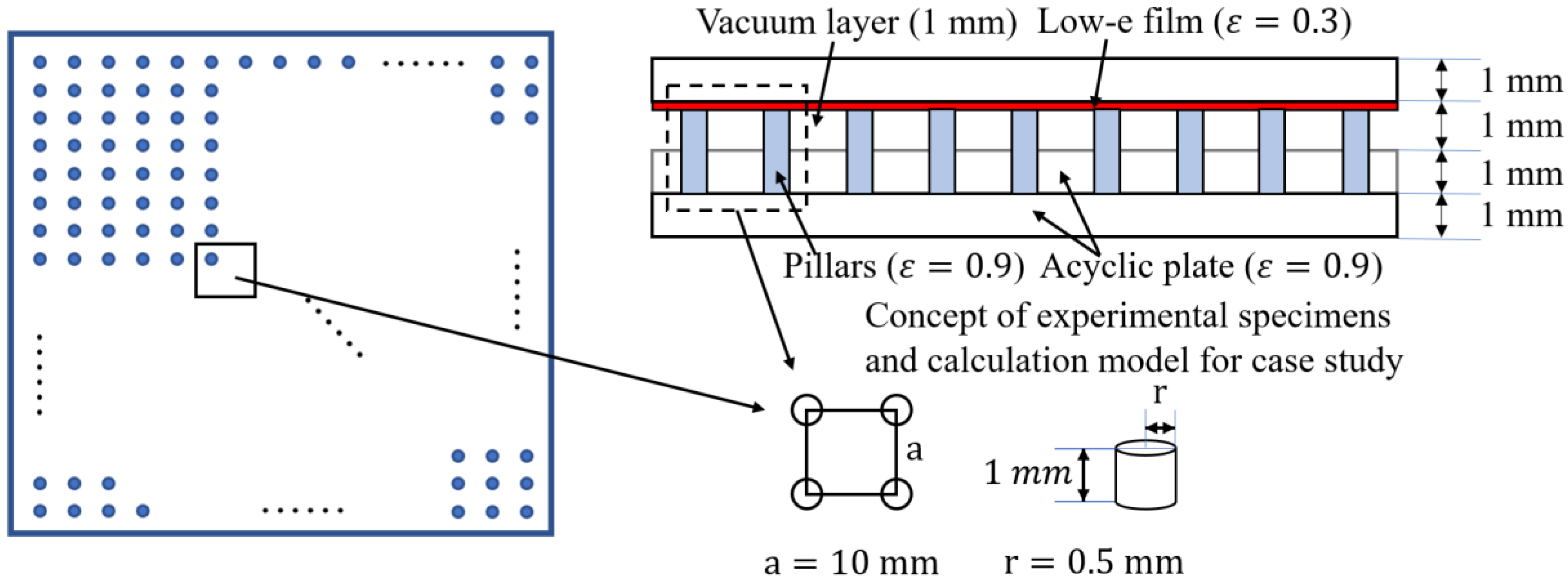
4.3. Framework of VIP Specimen for GHP Method and its Calculation Conditions and Result

Figure 12 shows the concept diagram of the VIP test specimens and models of the case study. In the GHP experiment, the specimen is pressed by hot and cold plates, and the pressure in the chamber is reduced to 0.1 Pa and 1 Pa, respectively. Figure 13 shows the comparison of the thermal conductivities obtained from the calculation and experimental result based on the pressure.
An element of the VIP is selected to represent the calculation conditions. The calculation conditions and specific size of the VIP for the standard model are also depicted in Figure 12. In this calculation, the thermal conductivities of the plastic cylinder (pillar) spacer, acrylic plate, and vacuum layer are 0.3 W / ( m · K ) , 0.2 W / ( m · K ) , and 0.106 mW / ( m · K ) (the thermal conductivity can be calculated by Equation (12)) [6,22], respectively, and the thermal emissivities of the acrylic plate and low-e film are 0.9 and 0.3, respectively. The temperature difference for the calculation is 25 °C.
Some influence factors exist in this experiment, particularly the gaps between the hot and cold plates and the specimens. Therefore, the experiment result can be calculated by Equation (15) to eliminate the influence of the gaps. In this experiment apparatus, the gaps are in the vacuum environment that is between the cold plate and specimen, specimen and thermocouple, and thermocouple and hot plate, respectively.
R V I P = R m R V a 1 R v a 2 R v a 3
Here, R V I P ( ( m 2 · K ) / W ) is the thermal resistance of a specimen; R m ( ( m 2 · K ) / W ) is the thermal resistance of the experimental result; and R V a 1 , R v a 2 , and R v a 3 are the thermal resistances of gaps 1, 2, and 3, respectively. Here, R v a = R v c + R v r and R v c can be calculated by Equation (12); this thermal resistance is not related to the thickness so the thermal resistance of the gaps is the same. R v r is calculated by Equations (14)–(16), and thermal emissivity ε = 0.9 . The experimental and optimization results that can be calculated by Equation (19) are shown in Table 1. The simulation and experimental results (optimized by Equation (19)) are compared and illustrated in Figure 13.
λ V I P = L v / R V I P
According to Figure 13, the results of the numerical model show a good agreement with the experimental results under a high vacuum. However, in the experiment, the sockets for the spacers also have gaps owing to the difference in the diameters that decrease the thermal conductivity. Furthermore, the result of the numerical model is lower than the one-dimensional (1-D) calculation result by Appendix A; this is probably because the numerical model can consider the thermal resistance in different axis directions. In addition, the thermal conductivity in the absence of the effect of spacers and plates shows the high performance of the evacuated space.

5. Case Studies for Vacuum Layer Type Translucent VIP

5.1. Calculation Conditions for Case Studies

In this section, the vacuum layer type VIP is further considered and its performance is verified based on different design plans. By considering the cost performance, the authors determined the specification of the component of the VIP, so that the thermal conductivities of the plastic cylinder spacers and acrylic plate are 0.3 W / ( m · K ) and 0.2 W / ( m · K ) , respectively. The other conditions are presented in Table 2.

5.2. Results and Discussion

The comparison of the results from the case studies is shown in Figure 14. The calculated thermal conductivity in Case 1 is higher than that in the standard case owing to the higher thermal emissivity. It seems that thermal conductivity can be improved further by an additional low-e film set; however, considering the cost of components and improvement of insulation performance, only one low-e film is enough. Case 2 shows a better performance because the multiple layers cause the thermal conductivity of the vacuum layer to become half that of a single layer. In this way, multiple layers can achieve a similar performance at a lower pressure; however, the thickness will increase. In Cases 3 and 5, the thermal conductivity of the vacuum layer decreases with the reduction in pressure. The standard case has the lowest thermal conductivity when compared with Case 4 owing to the low-emissivity effect. In summary, the most reasonable design should be in standard models as follows: a pressure of 0.1 Pa can achieve a good insulation performance or at a higher pressure with multiple layers, and the model is then covered with a low-e film to control the emissivity and coated with a gas barrier film. The arrangement of spacers should be in the span of 10 mm, which holds a vacuum layer structurally with a small thermal bridge.

6. Conclusions

(1)
The authors proposed a vacuum layer type slim and translucent VIP with the advantages of a low manufacturing cost and easy application.
(2)
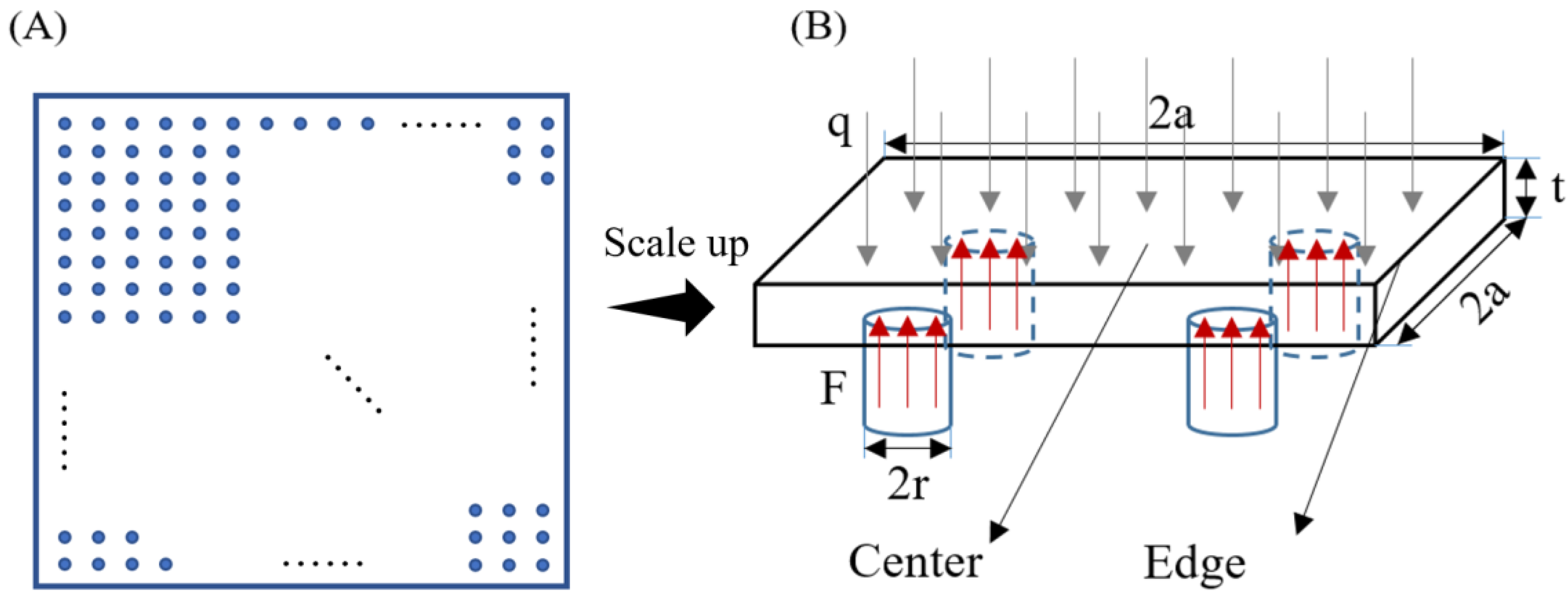
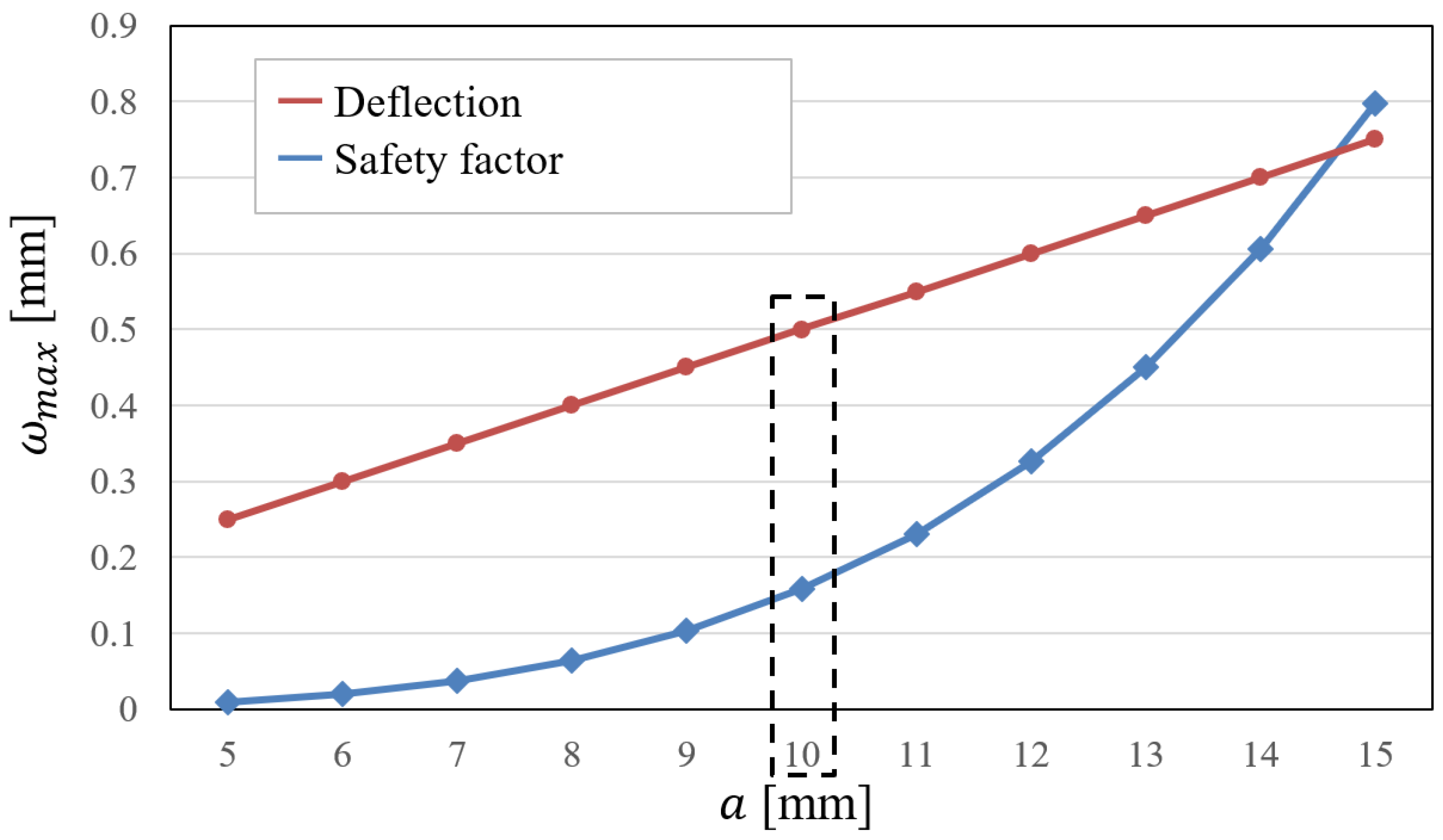
By using a structural calculation model, the specifications of the spacers and plastic plates that can hold the vacuum layer structurally were investigated. The result showed that the vacuum layer could be maintained when the span between the spacers was less than 10 mm.
(3)
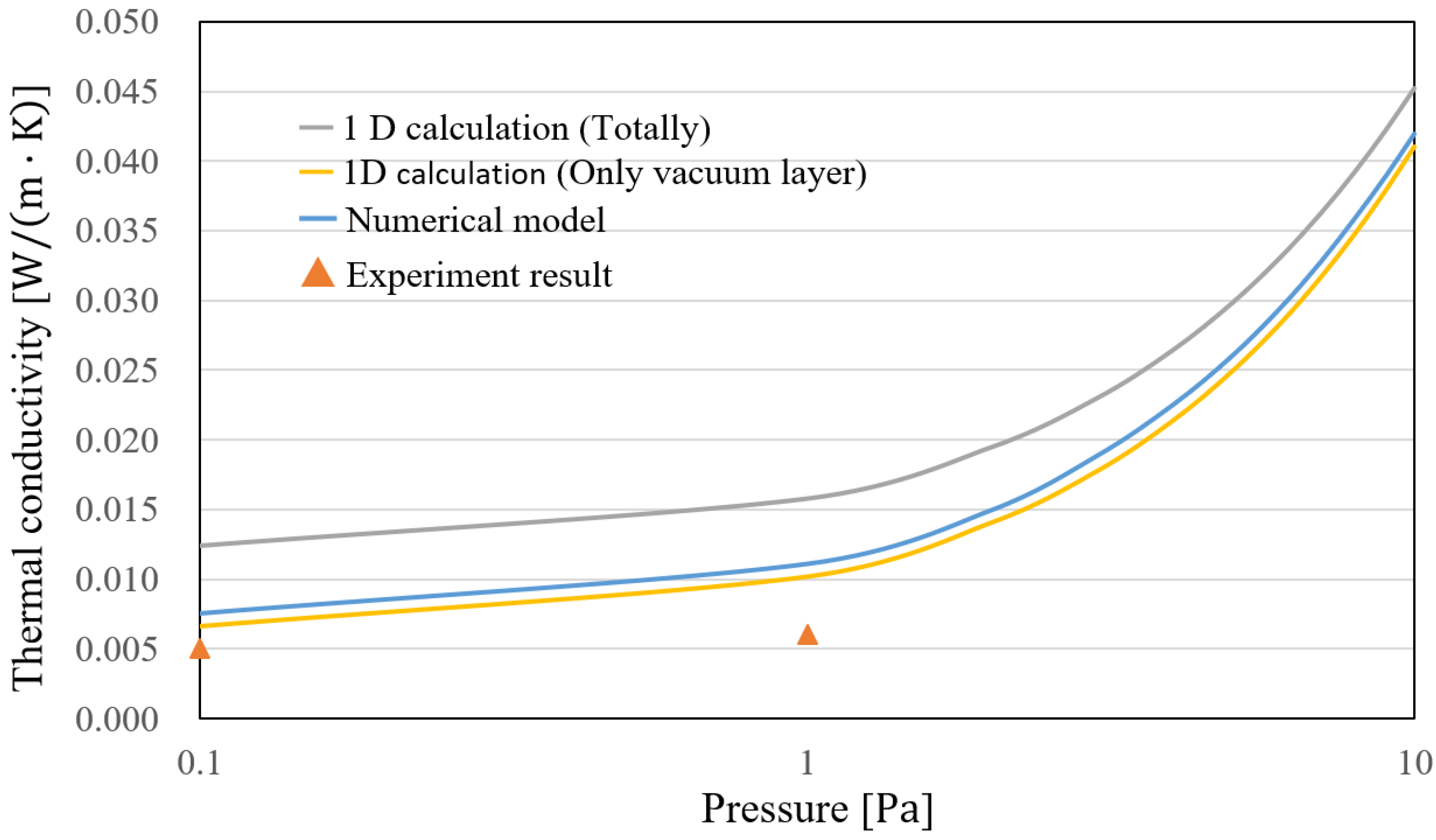
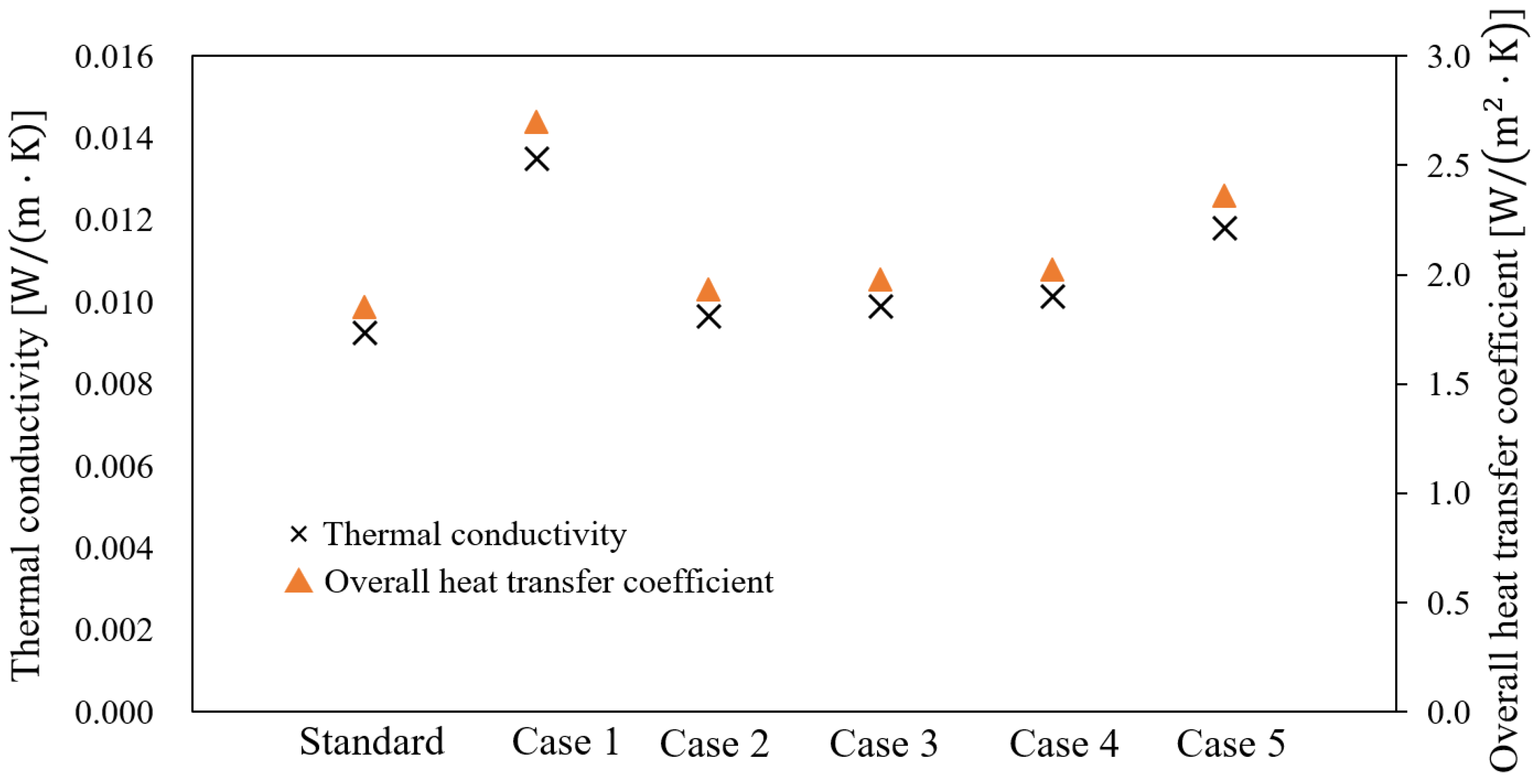
Heat transfer models were considered for the prediction of the thermal transmittance of the VIPs. The thermal conductivities of the VIPs were calculated by varying the calculation conditions of the pressure of the vacuum layer, thermal emissivity of the surface, and number of vacuum layers. The high-insulation performance was confirmed for future applications because the overall heat transfer coefficients were less than 2.0 W / ( m · K ) when the pressure of the vacuum layer was reduced to less than 0.1 Pa or a double vacuum layer was produced.
(4)
The result showed that the thermal conductivity of a double layer VIP under a pressure of 1.0 Pa was practically similar to that of a single VIP under a pressure of 0.1 Pa.
(5)
The numerical results were in better agreement with the experimental results under a pressure of 1 Pa because the numerical analysis can also consider the thermal resistance in different axis directions. Furthermore, to obtain a better insulation performance, using multiple layers instead of a lower pressure could reduce the product cost and lead to easy manufacturing of the product.

Acknowledgments

This study is financially supported by the Grants-in-Aid for Scientific Research of the JSPS (Research representative: Takao Katsura; Subject number: 15H05538). The authors also thank Yuji Mori at the Technical Center, Faculty of Engineering, Graduate School of Hokkaido University, Hokkaido Electric Power Co., Inc., Mitsubishi Chemical Corporation, TEIJIN FRONTIER CO., LTD., ULVAC, Inc., and Miyoshi Vacuum Packing for their assistance in the VIP test production.

Author Contributions

Zhang Yang and Takao Katsura proposed the prediction model and conceived the experiments; Makoto Nakamura, Masahiro Aihara and Katsunori Nagano assist performed the experiments; Zhang Yang and Takao Katsura analyzed the data; Zhang Yang wrote the paper.

Conflicts of Interest

The authors declare no conflict of interest.

Nomenclature

A Measurement area ( m 2 )
a Span between spacers (mm)
C Thermal conductance ( W / ( m 2 · K ) )
D Stiffness (N/m)
d Thickness (m)
d p Thickness of acrylic plate (mm)
d m Molecular diameter (nm)
E Young’s modulus (GPa)
G r Grashof number (-)
g Acceleration due to gravity ( m / s 2 )
K Absolute temperature (K)
k Boltzmann constant (J/K)
L v Thickness of vacuum layer (m)
l Mean free path of air (m)
M Molecular mass ( g / mol )
P Pressure (Pa)
P b Pressure ratio (-)
P 0 Atmospheric pressure (Pa)
P r Prandtl number (-)
Q Average electric power ( W )
R Thermal   resistance   ( ( m 2 · K ) / W )
T Temperature   ( K )
Δ T Temperature   difference   between   hot   and   cold   plates   ( K )
U Overall heat transfer coefficient ( W / ( m 2 · K ) )
v Kinematic viscosity ( m 2 / s )
Greek Symbols
α Convection heat transfer rate ( W / ( m 2 · K ) )
β Coefficient of volume expansion (-)
β 0 Accommodation coefficient (-)
γ Specific heat ratio (-)
σ Stefan-Boltzmann constant ( W / ( m 2 · K 4 ) )
λ Thermal conductivity ( W / ( m · K ) )
ε Emissivity (-)
μ Poisson ratio (-)
δ Coefficient when rectangular flat plate is functioned by uniform load (-)
ω ¯ m a x Maximum deflection (mm)
Subscripts
a Average
C Cold
c Conduction
m Mean
H Hot
P Plate
r Radiation
1, 2Surface 1 or 2
VIP Vacuum insulation panel
ν Vacuum layer
ν a 1 , ν a 2 , ν a 3 Gaps in GHP apparatus

Appendix A

This appendix provides the details of the 1-D calculation model.
Figure A1 presents the concept diagram of the 1-D calculation model.
Figure A1. One-dimensional calculation model of VIP.
Energies 10 02108 g0a1
The heat transmittance includes the radiant heat transfer in the vacuum space and conduction in the external surface and spacers. In this model, the heat transfer in the vacuum space is calculated as thermal resistance Ra ( ( m 2 · K ) / W ). When the spacers have a ratio of area “S” between the two plates, the thermal resistance Ra ( ( m 2 · K ) / W ) can be expressed as below.
R a = 1 ( λ v d v + α r ) ( 1 s ) + λ s d v s
Radiant heat transfer αr is calculated by the following equation:
α r = ε 1 ε 2 c b { ( T 1 100 ) 4 + ( T 2 100 ) 4 } 1 ( T 1 T 2 )
Thermal conductivity of vacuum layer λ v is calculated by the following equations: [19,20,21]
λ v = 18.2 d γ + 1 γ 1 β p M T
T 2 T 1 + T 2
From Equations (1)–(3) and the following equation, the apparent thermal conductivity of the vacuum layer including the spacer is calculated.
λ a = d v / R a
Here, λ v is the thermal conductivity of the vacuum layer ( W / ( m · K ) ); λ s is the thermal conductivity of the spacer ( W / ( m · K ) ); α is the radiant heat transfer ( W / ( m 2 · K ) ); d is the thickness of the vacuum layer ( m ); ε 1   and   ε 2 are the emittances of Plate 1 and Plate 2, respectively (-); C b is a constant of radiance ( W / ( m 2 · K 4 ) ); T 1   and   T 2 are the surface temperatures of Plate 1 and Plate 2, respectively ( K ); γ is the specific heat ratio c p / c v ; and β is the accommodation coefficient.

References

  1. Nature Publishing Group. Architects of a low-energy future. Nature 2008, 452, 520–523. [Google Scholar]
  2. Saari, A.; Kalamees, T.; Jokisalo, J.; Michelsson, R.; Alanne, K.; Kurnitski, J. Financial viability of energy-efficiency measures in a new detached house design in Finland. Appl. Energy 2012, 92, 76–83. [Google Scholar] [CrossRef]
  3. Lim, T.; Seok, J.; Kim, D.D. A Comparative Study of Energy Performance of Fumed Silica Vacuum Insulation Panels in an Apartment Building. Energies 2017, 10, 2000. [Google Scholar] [CrossRef]
  4. Capozzoli, A.; Fantucci, S.; Favoino, F.; Perino, M. Vacuum Insulation Panels: Analysis of the Thermal Performance of Both Single Panel and Multilayer Boards. Energies 2015, 8, 2528–2547. [Google Scholar] [CrossRef]
  5. Park, S.; Choi, B.-H.; Lim, J.-H.; Song, S.-Y. Evaluation of Mechanically and Adhesively Fixed External Insulation Systems Using Vacuum Insulation Panels for High-Rise Apartment Buildings. Energies 2014, 7, 5764–5786. [Google Scholar] [CrossRef]
  6. Collins, R.E.; Turner, G.M.; Fisher-Cripps, A.C. Vacuum Glazing—A New Component for Insulating Windows. Build. Environ. 1995, 30, 459–492. [Google Scholar] [CrossRef]
  7. Fisher-Cripps, A.C.; Collins, R.E.; Turner, G.M.; Bezzel, E. Stress and Fracture Probability in Evacuated Glazing. Build. Environ. 1995, 30, 41–59. [Google Scholar] [CrossRef]
  8. Garrison, J.D.; Collins, R.E. Manufacture and cost of Vacuum Glazing. Sol. Energy 1995, 55, 151–161. [Google Scholar] [CrossRef]
  9. Turner, G.M.; Collins, R.E. Measurement of Heat flow through Vacuum Glazing at elevated Temperature. J. Heat Mass Transf. 1997, 40, 1437–1446. [Google Scholar] [CrossRef]
  10. Lenzen, M.; Collins, R.E. Long-term Field Tests of Vacuum Glazing. Sol. Energy 1997, 61, 11–15. [Google Scholar] [CrossRef]
  11. Collins, R.E.; Simko, T.M. Current Status of the Science and Technology of Vacuum Glazing. Sol. Energy 1998, 62, 189–213. [Google Scholar] [CrossRef]
  12. Simko, T.M.; Fisher-Cripps, A.C.; Collins, R.E. Temperature-induced in Vacuum Glazing Modelling and Experimental Validation. Sol. Energy 1998, 63, 1–21. [Google Scholar] [CrossRef]
  13. Kim, J.; Jang, C.; Song, T. Combined heat transfer in multi-layer radiation shields for vacuum insulation panels: Theoretical/numerical analysis and experiment. Appl. Energy 2012, 94, 295–302. [Google Scholar] [CrossRef]
  14. Kwon, J.-S.; Jang, C.; Jung, H.; Song, T.-H. Vacuum maintenance in vacuum insulation panels exemplified with a staggered beam VIP. Energy Build. 2010, 42, 590–597. [Google Scholar] [CrossRef]
  15. Bouquerel, M.; Duforestel, T.; Baillis, D.; Rusaouen, G. Heat transfer modelling in vacuum insulation panels containing nanoporous silica—A review. Energy Build. 2012, 54, 320–336. [Google Scholar] [CrossRef]
  16. Kwon, J.-S.; Jang, C.; Jung, H.; Song, T.-H. Effective thermal conductivity of various filling materials for vacuum insulation panels. Int. J. Heat Mass Transf. 2009, 52, 5525–5532. [Google Scholar]
  17. Johanssonn, P.; Adl-Zarrabi, B.; Hagentoft, C.-E. Using transient plane source sensor for determination of thermal properties of vacuum insulation panels. Front. Archit. Res. 2012, 1, 334–340. [Google Scholar] [CrossRef]
  18. Collins, R.E.; Davis, C.A.; Dey, C.J.; Robinson, S.J.; Tang, J.Z.; Turner, G.M. Measurement of local heat flow in flat evacuated glazing. Int. J. Heat Mass Transf. 1993, 36, 2553–2563. [Google Scholar] [CrossRef]
  19. Timoshenko, S.; Woinowsky-Krieger, S. Theory of Plate and Shell; McGraw-Hill Book Company: Columbus, OH, USA, 1959; pp. 106–108. [Google Scholar]
  20. Roark, R.J.; Warren, C.; Young, R.G. Budynas. Formulas for Stress and Strain, 7th ed.; McGraw-Hill Professional: New York, NY, USA, 2001; pp. 508–509. [Google Scholar]
  21. Gan, G. Thermal transmittance of multiple glazing: Computational fluid dynamics prediction. Appl. Therm. Eng. 2001, 21, 1583–1592. [Google Scholar] [CrossRef]
  22. Springer, G.S. Heat Transfer in Rare Field Gases. Adv. Heat Transf. 1971, 7, 163–218. [Google Scholar]
  23. Jousten, K.; Jitschin, W.; Sharipov, F.; Pumps, P.D.; Dirscherl, J.; Lachenmann, R.; Jünemann, A.; Friedrichsen, I.; Lippelt, E.; Kossek, B.; et al. Handbook of Vacuum Technology, 1st ed.; Jousten, K., Ed.; Wiley: Weinheim, Germany, 2008; pp. 51–81. [Google Scholar]
  24. Eckert, E.R.G.; Drake, R.M. Heat and Mass Transfer, 2nd Revised ed.; McGraw-Hill Inc.: Columbus, OH, USA, December 1959. [Google Scholar]
Figure 1. Concept diagram of the VIP application to buildings.
Energies 10 02108 g001
Figure 2. Outline of the mechanical analysis of the VIP, (A) plan and (B) element analysis.
Energies 10 02108 g002
Figure 3. Schematic of the calculation model. (A) only atmospheric pressure P0; (B) only elastic effect.
Energies 10 02108 g003
Figure 4. Calculation results of the maximum deflections at different spans.
Energies 10 02108 g004
Figure 5. Meshing in finite element analysis (3-D).
Energies 10 02108 g005
Figure 6. Total deformation in a VIP element (3-D).
Energies 10 02108 g006
Figure 7. Schematic of heat transfer through a double plate unit.
Energies 10 02108 g007
Figure 8. Manufacturing flow of the VIP specimens.
Energies 10 02108 g008
Figure 9. Component diagram of the gas barrier film.
Energies 10 02108 g009
Figure 10. Industrial manufacture cost of transparent evacuated insulation products.
Energies 10 02108 g010
Figure 11. Schematic of the guarded hot plate apparatus.
Energies 10 02108 g011
Figure 12. Concept diagram of the VIP specimen and model for the case study.
Energies 10 02108 g012
Figure 13. Comparison of the simulation and experimental results.
Energies 10 02108 g013
Figure 14. Comparison of the calculated results for the case studies.
Energies 10 02108 g014
Table 1. Experimental results by GHP.
Pressure (Pa)Experimental Thermal Conductivity
λm (mW/(m·K))
Experimental Thermal Resistance
Rm ((m2·K)/W)
Thermal Resistance in the Gaps
Rva ((m2·K)/W)
Thermal Resistance of VIP (Calculated)
RVIP ((m2·K)/W)
Thermal Conductivity of VIP (Calculated)
λVIP (W/(m·K))
0.12.91.450.210.830.005
13.61.170.170.650.006
Table 2. Calculation conditions in the case studies.
ConditionsLv (m)P (Pa)λv (W/(m·K))ε1ε2Layers
Standard1.0 × 10−30.10.0001060.30.91
Case 110.001060.90.91
Case 210.000530.30.92
Case 30.50.000530.30.91
Case 40.10.0001060.90.91
Case 510.001060.30.91

