1. Introduction
From the energy point of view, the wellbeing of humanity requires more and more renewable energy and efficient and low cost energy conversion and transfer systems. A large part of these systems have power trains with transmissions that have a variable speed/transmission ratio, for instance, the transmissions of vehicles, variable speed wind turbines and wave energy turbines. To enable the optimization of a driving machine, the crucial issue of these transmissions is to obtain the required speed of the output shaft for an arbitrary (optimal) speed of the input shaft, independent of each other, and with as high as possible efficiency and as low as possibly cost. This is because the higher the efficiency, the lower the emission of harmful gasses.
Continuously variable transmissions (CVTs) were the first to realize the required speed of the output shaft for certain speed of the input shaft continuously, without interruption. They are mostly applied in vehicles to enable operation at the lowest possible speed and highest possible load. There are many CVT configurations. Primitive versions consist of a variator and possibly a conventional gear transmission, while advanced CVTs, the so-called infinitely variable transmissions (IVTs), consist of one or more variators coupled with a differential mechanism and some type of conventional transmission. They can control the engine speed independently of the vehicle speed, and partially avoid the low efficiency region of the engine map. One more advantage is the possibility of outputting zero speed within the operating range.
CVTs primarily differ in the type of variator used: commonly the belt type [
1,
2,
3,
4,
5,
6,
7,
8,
9,
10], but also hydrostatic [
11,
12,
13], traction [
14,
15,
16], and electric (e-CVT) [
17,
18,
19] ones, based on the ability of variable speed electric machines to continuously change their shaft speed from zero to an arbitrary required speed. Infinitely variable transmissions [
20,
21,
22,
23] have been successfully applied as vehicle transmission.
The paradigm of electric CVT applications are a series hybrid electric vehicles (HEVs) [
24] in which the engine energy is first converted into electrical, in the generator, where it is passed through the control circuitry and then delivered to the electric motor, which converts the electrical power back to mechanical and drives the wheels. All other types of HEVs are also comprised of an electric CVT typically combined with a differential mechanism (DM) [
25,
26,
27,
28,
29].
The main disadvantages of common CVTs are low efficiency due to friction losses in the variator and the high capital cost of electric machines, which are low in energy efficiency. In electric CVTs, a principal shortcoming is double conversion from mechanical to electric energy and vice versa, as well as from AC to DC and vice versa. The control system required to enable independency of the input and output shaft while maintaining an optimal energy management strategy, especially in HEVs, is ever-increasing in complexity and cost.
An intriguing use of IVTs has been proposed, whereby the IVT converts the arbitrary variable speed of the input shaft into the required (variable or constant) speed of the output shaft, independent of the rest of transmission (including a possible control system). This conversion is enabled by designing the DMs in the way that the speed of transmission output shaft is linearly dependent with the speed of the third external shaft connected to some machine with a controllable speed, commonly an electric generator. Thus, controlling the generator speed, the output shaft speed is controlled. This proposed method is referred to as an independently controllable transmission (ICT) [
30,
31,
32]. It has promised to solve most of the problems associated with variable-speed transmissions, with or without a control system. ICTs commonly have four shafts [
31,
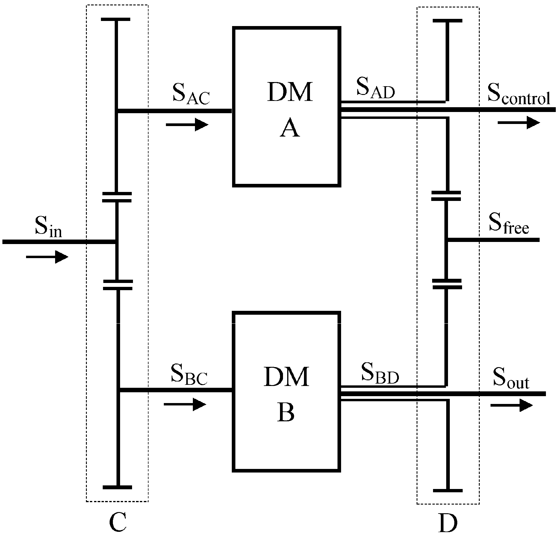
32]: an input shaft, an output shaft, a control machine shaft and a so-called free shaft. The paradigmatic transmission is presented by Hwang et al. [
30] (
Figure 1). It consists of two DMs, A and B, connected in parallel by two conventional gear transmissions (CGTs), C and D. The transmission input shaft S
in, controls the speeds of the two DMs input shafts, S
AC and S
BC*, while the shaft S
control, connected to some variable speed machine with a speed controller, commonly an electric generator, controls the speed of the transmission output shaft S
out, independently of the transmission input speed. Thus, according to the Willis equation [
33,
34], the speeds of the DMs rest shafts, S
AD and S
BD, run at uncontrollable speeds, determined by the transmission input and output shaft speeds. As result, the independent control of one output shaft is achieved, but one surplus, so called “free shaft”, S
free, appears having uncontrollable variable speed that annuls the achievement. It is established by the authors, and will be demonstrated below, that this shortcoming is peculiar to the transmissions presented in [
30,
31,
32].
Müller [
33] proposed an ICT with three DMs connected in parallel with two or three CGTs, whereby the problem of surplus “free shaft” was solved, but in the basic configuration, the problem of zero power in a couple of the shafts appeared. It was solved by adding one gear to the CGT with the uncontrollable shafts. Its shaft was connected to control motor controlling the transmission input shaft speed, fed by generator controlling the output shaft speed, driven by one of the controllable shafts. However, this proposed system is no longer considered an ICT without a control system and using one more DM enhances the price of the transmission.
In this paper, we succeed in redesigning the transmissions proposed in earlier studies [
30,
31,
32] and have achieved a series of kinematically feasible transmissions, without a control system, with a single input and single output shaft. These transmissions are applicable wherever the need exists for the speed(s) of one or more shaft(s) to not be affected by the speed of another’s.
2. Kinematic Synthesis of the Transmission
2.1. Defining the Transmission
The transmission is based on a fundamental feature of the differential mechanism: two shafts can rotate at any variable and mutually independent speeds as long as the third shaft rotates at the speed that, at any moment, satisfies the Willis equation [
33,
34], and while the constraints of the differential mechanism related to limited speed ratio ranges of its shafts and limited values of basic gear ratio for a certain power flows are satisfied.
The proposed transmission is the simplest possible. It has just two external shafts, the input S
in and output S
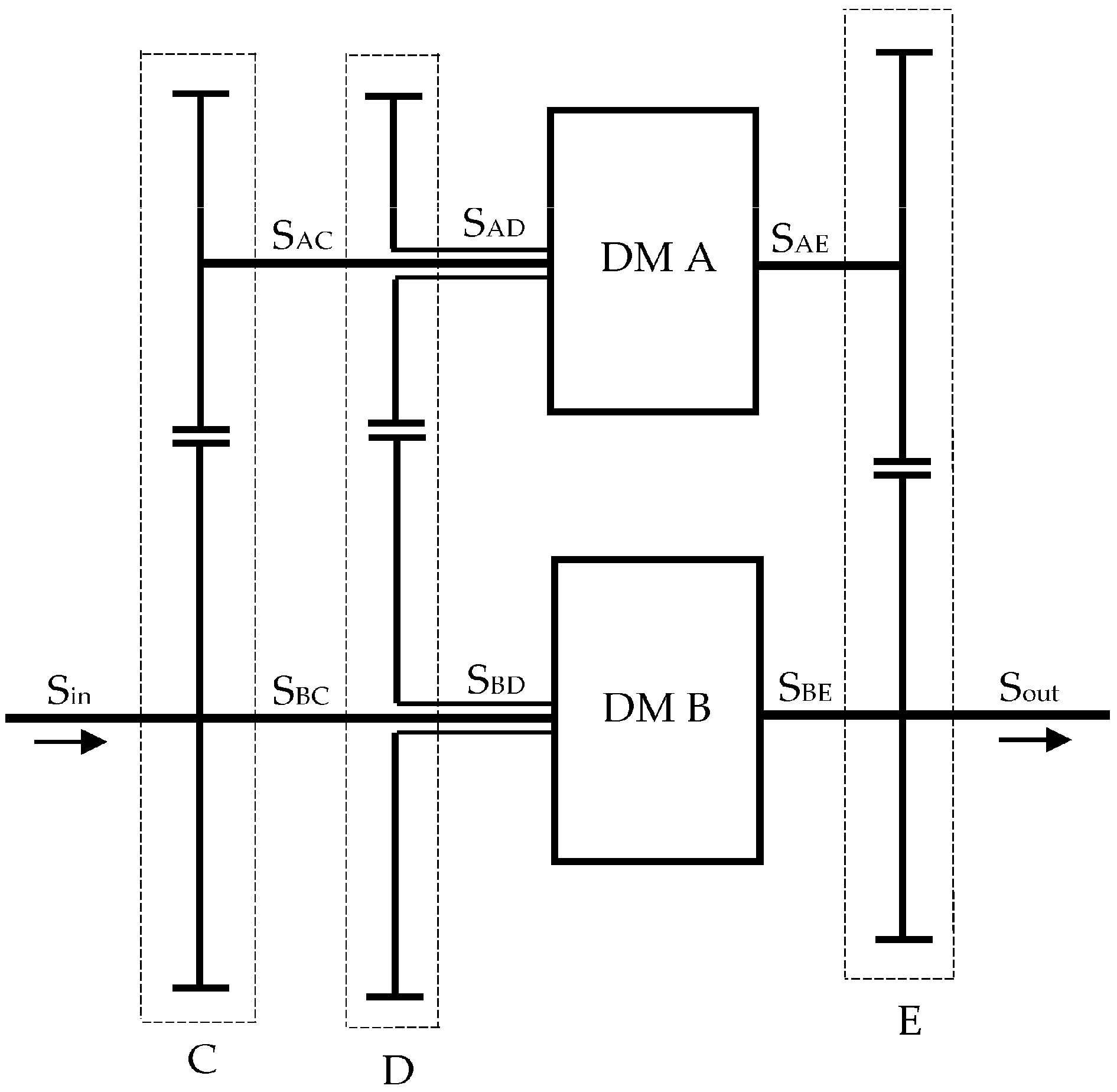
out, having mutually independent speeds; that is, absent the control system and any control machine or device. Only the speeds of the input and output shafts are controlled by the controllers of the machines or devices connected to them, or one of them can be random—as in the case of wind turbine. The fundamental architecture is presented in
Figure 2. It consists of two simple (one carrier) differential mechanisms, A and B, mutually connected in parallel by three CGTs, C, D and E, each consisting of two gears. As is common for DMs, one of the three shafts is hollow, with one of the rest shafts passing through it. In this transmission, CGT C is connected with DMs A and B by shafts S
AC and S
BC passing through hollow shafts S
AD and S
BD connecting the CGT D with DMs. It is worth noting that CGT D can also be placed on the opposite (right) side of DMs.
To achieve the independence of the speeds of the input Sin and the output Sout shafts, in other words, the independence of the shaft speeds of CGTs C and E, the output shaft should be independently controlled by the machine connected to it. As the speed of the CGT C shaft is controlled by the driving machine, the CGT D compensates the difference in speed between shafts of CGT C and E and runs at uncontrolled variable speeds.
The transmission feasibility, i.e., its possibility to meet the required features for the prescribed energy/power flows, depends on the distribution of the DM shafts (addressing the carriers and central gears shafts to the certain gear/shaft of the certain CGT), the transmission speed ratio and the speed ratios of CGTs, which are the same as the teeth ratio of CGT gears, and are also the same as the speed ratios of the corresponding shafts of DMs A and B. Because the shafts of a single DM can be distributed six ways, the DMs can be connected in 62 = 36 different ways, thus resulting in 36 different transmissions. There can be also 12 different power flows resulting in a total of 432 different transmissions. For each of them, the following procedure was carried out to avoid the constraints of the DMs and thus check their feasibility:
First, follow the rule of DMs shaft powers: they are positive (input) for the same signs of the speed and torque, and negative (output) in the opposite case.
Choose which of DMs shafts will be connected to shafts of CGTs.
Distribute the speed and torque signs to obtain the required power flows.
Check whether at least one of the shafts on the DMs has a torque sign different to two of the rest.
Check whether at least one of the shafts on the DMs has a power sign different to two of the rest.
Derive the formulas for the basic gear ratios (BGRs) of the DMs A and B as a function of the speed ratios α, β and γ (see below). This enables the determination of the next point.
Determine the ranges of speed ratios α, β and γ, see below.
Check whether those ranges results in the required values of the BGRs of DMs A and B, see below.
Check whether the speeds of the summation shafts of the DMs A and B lie between the speeds of the central gear shafts [
33,
34], meaning that at least one of the central gear shafts must have the same speed sign as the summation shaft.
Check both A and B DMs to determine whether the power flow condition is satisfied that results in the speed ratio ranges of the shafts of DMs A and B depending on their BGRs.
Check whether those ranges of speed ratios are convenient for the planned transmission.
After analyzing, dozens of transmissions were found feasible. The DM shaft distribution and power flows of one of these feasible transmissions is shown, as an example, in
Table 1 where the shaft speeds are marked as
n, torques as
T and powers as
P, and their subscripts mark the related shaft.
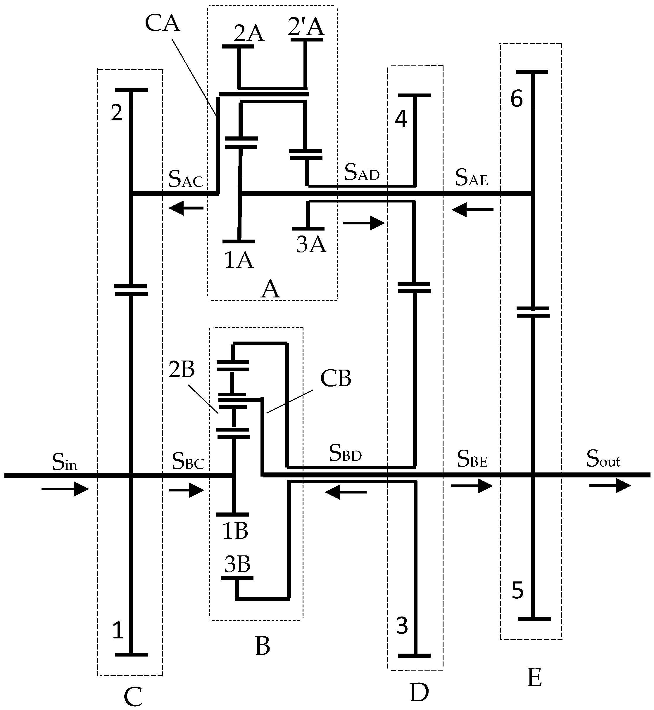
The design and energy/power flows of the transmission is presented in
Figure 3 where it can be seen that the energy/power of shaft S
AE enters the DM A and flows from it to CGTs C and D, wherefrom it flows toward the CGT E and back to the shaft S
AE. Thus, it circulates inside the transmission in two closed circles and never reaches the output shaft. Distinctly, the entire power of the input shaft flows directly to the output shaft, reduced by the losses in the DMs.
2.2. Obtaining the Basic Gear Ratios
The capital task for designers is to determine the basic gear ratios of the DMs for the prescribed values of the speed ratios of the CGTs, i.e., of the DM shafts connected by CGTs, for a certain distribution of the DM shafts.
The Willis equation (Equation (1)) [
33,
34] relates the speeds of the DMs and their basic gear ratios
i0A and
i0B:
The basic torque equations of the DMs (Equation (2)) [
33,
34] are
where
η0A and
η0B are the basic efficiencies,
i0A and
i0B are the basic gear ratios and
rA and
rB are the exponents of the
η0A and
η0B of DMs A and B, respectively. This implies that the basic gear ratio must be positive if the ratio of central gear torques is negative and opposite. The values
rA and
rB assume the value of unity with a positive or negative sign, depending on the direction of power flows, the range of the basic gear ratios and the range of speeds of the DM central gear. Thus, neglecting the power losses, according to
Table 1, the basic gear ratio of DM A is positive and that of DM B is negative.
Accounting for the torque equilibrium Equation (3) [
33,
34]:
it follows that basic gear ratio of DM A is smaller than unity.
It can be seen from
Table 1 that the fundamental kinematic conditions for both DMs are fulfilled: the speeds of the summation shafts of DMs A and B lie between the speeds of the difference shafts [
33,
34], meaning that at least one of the central gear shafts has the same speed sign as the summation shaft. The power flow conditions (Equation (4)) [
34] for DMs are
The condition
nBC/
nBD > 0 is obviously fulfilled, see
Table 1, while, after deriving the speed ratio of central gears of DM A from Equation (1):
in Equation (4) is reduced to
which is obviously fulfilled.
The basic torque and power conditions are fulfilled as well, because the signs of torques and powers of the three shafts of the DMs are not same, see
Table 1.
Being connected by CGTs, the shafts of DMs A and B have mutually linearly dependent speeds determined by the transmission ratios, i.e., by the number of teeth in the CGTs:
where
nBC and
nAC are the speeds of shafts S
BC and S
AC, respectively, and
z1 and
z2 are the number of teeth of gears 1 and 2, respectively;
where
nBE and
nAE are the speeds of shafts S
BE and S
AE, respectively, and
z5 and
z6 are the number of teeth of gears 5 and 6, respectively;
where
nBD and
nAD are the speeds of shafts S
BD and S
AD, respectively and
z3 and
z4 are the number of teeth of gears 3 and 4, respectively.
Because the Willis equations (Equation (1)) show that the basic gear ratios are defined by their shaft speeds, it means that they should be also related to the speed ratios
α,
β and
γ. By substituting Equations (7)–(9) into Equation (1), the following is obtained:
Equation (10) is valid for any speed ratios of the shafts, including the coupling point where all the speeds are equal, i.e., their ratios are equal to unity. Consequently, the final expressions for basic gear ratios of DMs are obtained:
From condition
i0B < 0, it follows that the possible ranges of
α,
β and
γ are:
The condition 0 < i0A < 1 is found to be fulfilled for the chosen ranges γ < β < α. Because both fractions in formula for i0A (Equation (11)) are positive, the condition i0A > 0 is obviously fulfilled. Solving the inequation i0A < 1, it is obtained , wherefrom follows , which is true and confirms that the condition is fulfilled.
The basic gear ratios calculated in this way result in a linear dependence of the speeds of shafts SAE and SBE. Thus, these shafts are able to control the speeds of each other, even when they are not connected with each other. That offers plenty of possible applications.
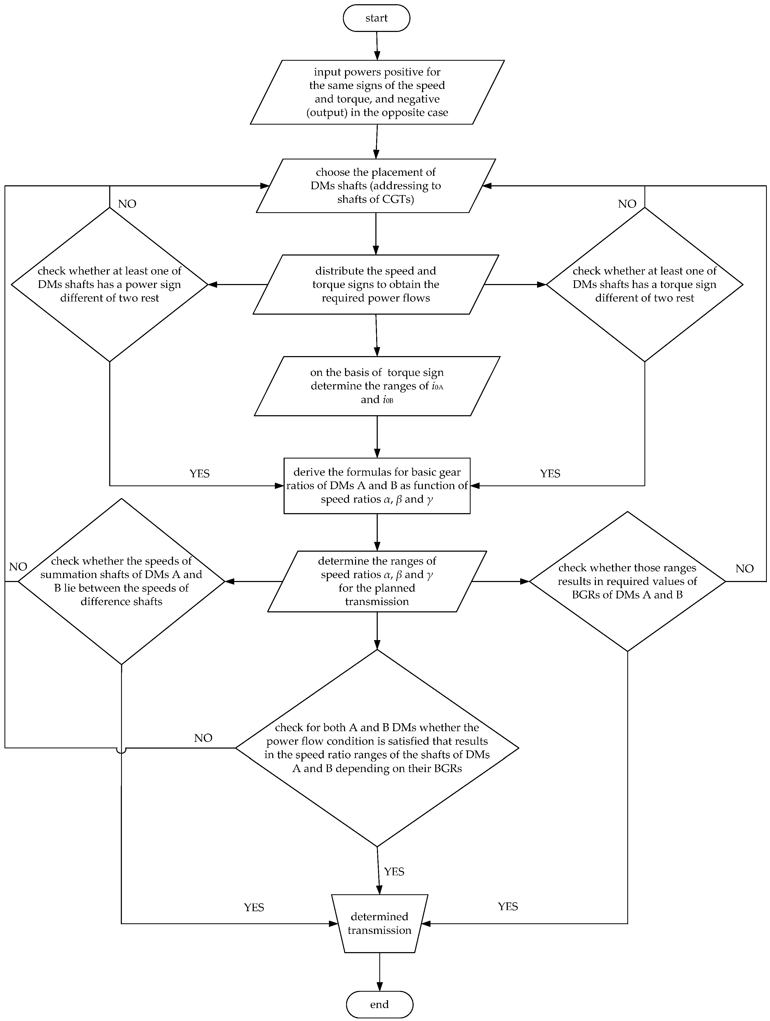
The procedure of designing the transmission is presented as a block diagram in
Figure 4.
2.3. Numerical Example
For the chosen values of the speed ratios, α = −1, β = −2/3 and γ = −3/5, the basic gear ratios are calculated: i0A = 3/4 and i0B = −5. From the equality of the center distances of CGTs gears, for a chosen number of teeth of gear 1, z1 = 80, the following number of teeth of CGTs gears are obtained: z1 = 80; z2 = 80; z3 = 100; z4 = 60; z5 = 96; z6 = 64.
From the equality of the center distances of the mated gears of the DMs, taking into account the assembly and neighboring conditions, the following number of teeth in the gears are obtained:
z1A = 28;
z2A = 28;
z2′A = 32;
z3A = 24;
z1B = 19;
z2B = 38;
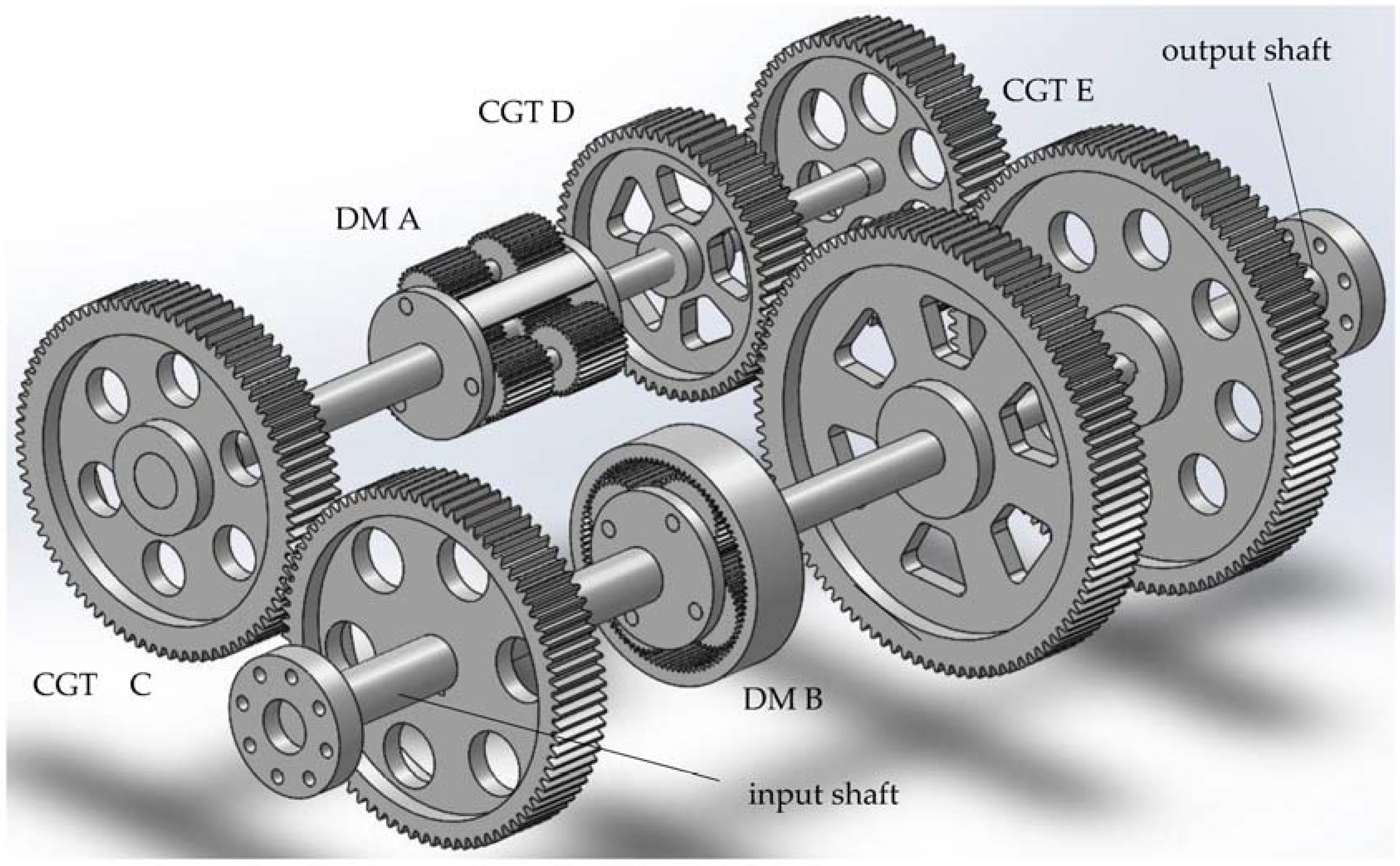
z3B = −95. From that, in accordance with assembly condition of DMs, the number of planets in DM A can be three or four, while in DM B it should be four. The transmission is drawn in 3-D in
Figure 5.
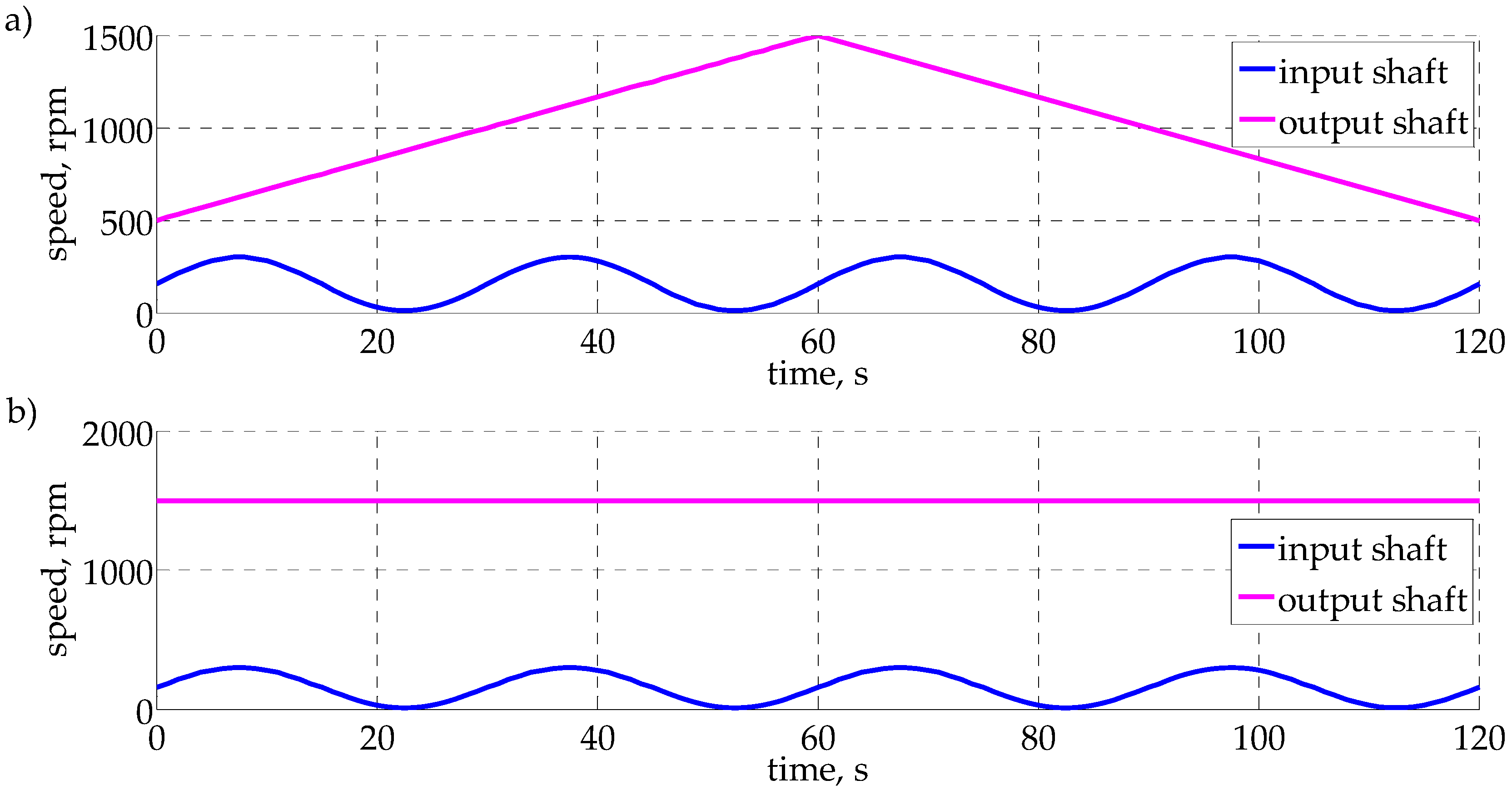
A 120 s speed history of both shafts S
in and S
out is presented in
Figure 6. The input shaft has a sinusoidal input speed that varies from 5 to 300 rpm and two output speed histories: (
Figure 6a) linearly increasing phase from zero to 1500 rpm in first minute followed by a linearly decreasing phase, from 1500 rpm to zero, in the last minute; and (
Figure 6b) a constant output speed. It is obvious that the output shaft speed is independent from the input shaft speed.
3. Powers and Efficiency
From the torque Equations (2) and (3) of the DMs, four power equations take rise:
According to the conservation of energy law and accounting for the power signs determined pursuant to the powers of the DMs, the powers of the CGTs are related as follows:
where
Pin and
Pout are the input and output powers, respectively, and
ηg is the efficiency of the CGTs, taken as the same for any pair of gears.
Thus, seven equations are obtained for a system which has eight unknowns and one degree of freedom. After solving, the result is strange: the powers of the input and output shaft are close to zero. This is because the following is obtained when Equations (13)–(16) are divided with each other:
where
a and
b are the calculation constants:
It can be seen that the powers of the DM shafts, mutually connected by CGTs, are linearly dependent, as well as their torques and speeds. Moreover, since the constants
a and
b are close to unity and neglecting the DM power losses (
η0A =
η0B =
ηg = 1), they become equal to unity, because:
Consequently, the power ratios of the DM shafts connected with the CGTs become mutually equal and equal to negative unity:
Obviously, the power ratios attitudes are equal (or closely different), meaning almost the entire power of a particular DM shaft flows, over the corresponding CGT, to the other DM; thus, the powers of the input and output shaft are close to zero, and the huge part of the power circulates inside the transmission. Therefore, to transmit the power from the input to output shaft, the transmission should be designed to carry a load much higher than it transfers! That makes no sense. It is interesting that the same result is obtained for any distribution of DM shafts!
In the original ICTs [
30,
31,
32], e.g.,
Figure 1, where the CGTs consist of three gears, the result is slightly different: the power ratios of the DM shafts are equal to unity.
and consequently the transmission input power is split in to two equal DM input powers. The transmission output power consists of the powers of two shafts, Sout and Scontrol, with mutually controllable speeds. The power of the “free shaft”, Sfree, has uncontrollable variable speed that annuls the purpose of the transmission. It is unavoidable, because, in accordance with Equation (24), its power is always the sum of the same sign powers of shafts SAD and SBD. This results in the real inability of the ICTs to convert the variable speed of the input shaft into the controllable speed of the output shaft.
When the power flows of DM A shafts S
AC and S
AE are reversed in the transmission of interest, as in
Figure 2, the power analysis results in the equation:
This means the input power is divided in to two and the output power is the sum of two; there are no zero shafts, there is no free shaft and everything is fine. However, the determined ranges of α, β and γ cannot result in the required basic gear ratio of DM A for any distribution of its shafts. Thus, the system is kinematically unfeasible.
4. Discussion
In this paper, a seemingly great achievement has been accomplished. A transmission was synthesized that is able to run the input and output shaft independently of each other, without a problematic additional external shaft that appears in previously proposed ICTs [
30,
31,
32], and without a control system. However, it is proven that this transmission is not able to transmit the power. Consequently, it led to the conclusion that any of originally proposed ICT is practically unfeasible.
However, it would be a pity not to utilize the discovery of mechanical transmission able to convert the arbitrary speed of one shaft to the required arbitrary speed of another, without a control system, without a variator, without a torque converter and without a control system—just gears and shafts. It is necessary, in some way, to achieve an input and output speed different from zero, i.e., to disrupt Equation (23) in such a way that the power ratios become different from negative unity. To that end, the transmission presented in paper [
35] is proposed. An even better solution can be achieved by removing CGT E from the transmission presented herein, and connecting shaft S
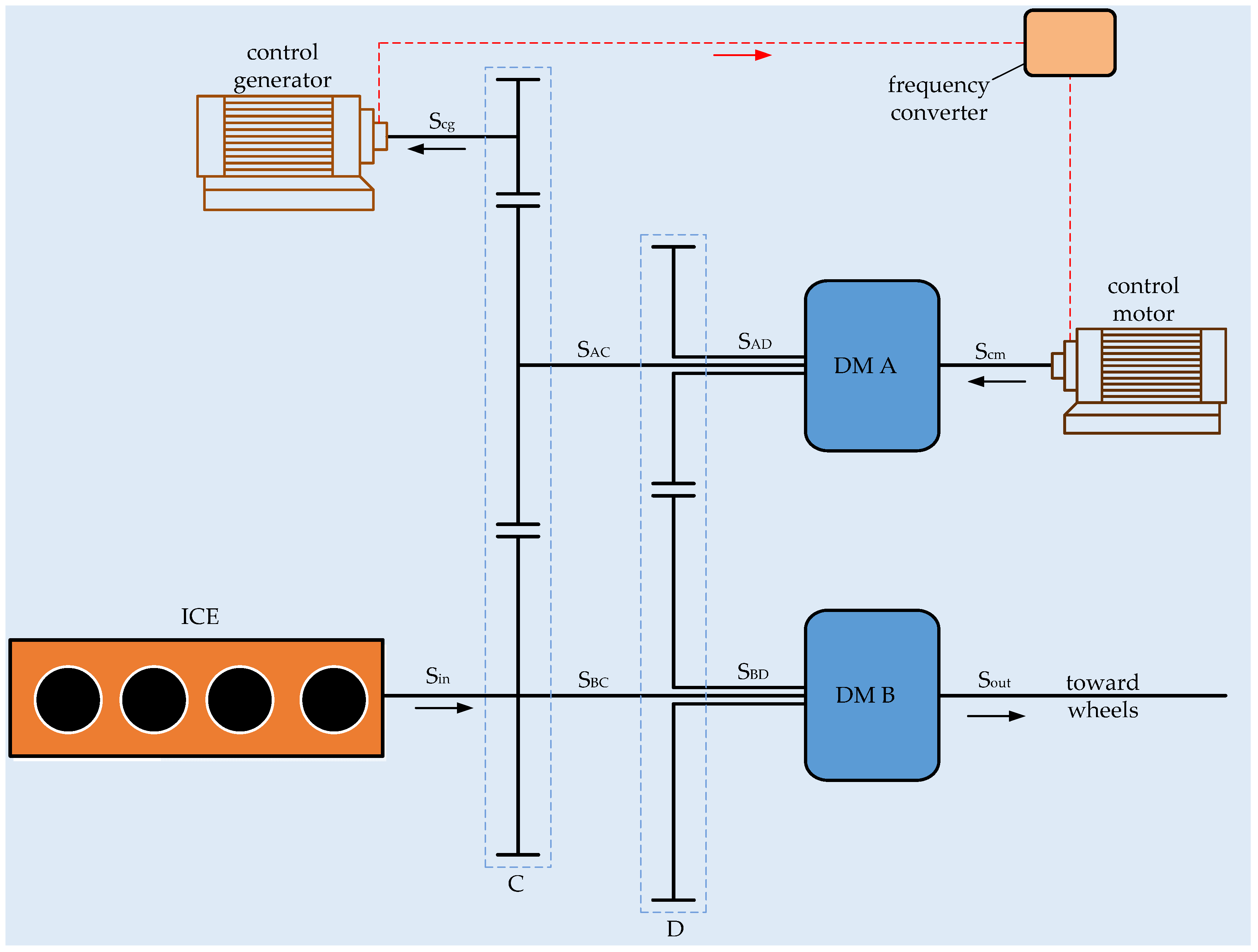
AE to a control motor. It should be noted that the control motor has a speed that is linearly dependent on the transmission output speed, and it controls the speed of the output shaft. Now, the magnitudes of output and control motor powers can even be the same, but the output power exists: it is equal to the control motor power. Thus, the control motor should be, via a frequency converter, fed by a generator that can be connected to the CGT C increased by one gear. Such a hybrid transmission, intended for vehicles propelled by an internal combustion engine (ICE), is presented in
Figure 7. The vehicle speed is controlled by a control motor shaft S
cm, and a control generator shaft S
cg, by the help of a control system that runs at a speed optimal for minimum fuel consumption at any vehicle speed. In this energy system, the energy of the control motor circulates in a closed circle, i.e., control generator–control motor–S
cm–DM A–CGT C–S
cg–control generator, while the ICE energy, via DM B, flows directly toward the wheels. By adding a high voltage battery pack and a DC/AC inverter to that transmission, an advanced, highly competitive plug-in hybrid electric vehicle can be obtained.
5. Concluding Remarks
The feasibility of ICTs is analyzed in this paper. It was proven that the ICTs proposed so far are practically inapplicable. Particularly, an ICT with two DMs and only one input and one output shaft, with variable speeds independent of each other, is presented and found kinematically feasible, but the power analysis shows that a huge power circulates inside the transmission, while the powers of the input and output shafts are almost zero or lawfully close to zero. Thus, it is not possible to transmit the power from an input shaft with a variable or constant speed to an output shaft with a variable or constant speed independent of the input shaft speed, without a control system. A conclusion can be applied from the analysis of any of the other originally proposed ICTs.
However, following the analyzed transmission, as a sign-post for further investigations, an example of an ICT expanded for two electric machines is proposed that should result in novel, competitive system of energy conversion and management, applicable in hybrid electric vehicles. Test benches and simulation programs for the hybrid transmission are planned in the Power Transmission Laboratory in the Mechanical Engineering Department of the University of Split, Croatia.
