Next Article in Journal
Efficacy of Transcutaneous Transseptal Orbital Decompression in Treating Acute Retrobulbar Hemorrhage and a Literature Review
Previous Article in Journal
Skeletal Stability after Bilateral Sagittal Split Advancement and Setback Osteotomy of the Mandible with Miniplate Fixation
 
 
Craniomaxillofacial Trauma & Reconstruction is published by MDPI from Volume 18 Issue 1 (2025). Previous articles were published by another publisher in Open Access under a CC-BY (or CC-BY-NC-ND) licence, and they are hosted by MDPI on mdpi.com as a courtesy and upon agreement with Sage.
Article

The Comprehensive AOCMF Classification System: Mandible Fractures—Level 2 Tutorial

by
Carl-Peter Cornelius
1,*,
Laurent Audigé
2,3,
Christoph Kunz
4,
Randal Rudderman
5,
Carlos H. Buitrago-Téllez
6,7,
John Frodel
8 and
Joachim Prein
4
1
Department of Oral and Maxillofacial Surgery, Ludwig Maximilians Universität, München, Germany
2
AO Clinical Investigation and Documentation, AO Foundation, Düebendorf, Switzerland
3
Research and Development Department, Schulthess Clinic, Zürich, Switzerland
4
Clinic for Oral and Craniomaxillofacial Surgery, University Hospital Basel, Basel, Switzerland
5
Plastic, Reconstruction and Maxillofacial Surgery, Alpharetta, Georgia
6
Institute of Radiology, Zofingen Hospital, Zofingen, Switzerland
7
Hightech Research Center for CMF Surgery, University of Basel, Basel, Switzerland
8
Division of Facial Plastic Surgery, Department of Otolaryngology-Head & Neck Surgery, Geisinger Medical Center, Danville, PA 17822, USA
*
Author to whom correspondence should be addressed.
Craniomaxillofac. Trauma Reconstr. 2014, 7(s1), 15-30; https://doi.org/10.1055/s-0034-1389557
Submission received: 1 September 2014 / Revised: 1 October 2014 / Accepted: 1 November 2014 / Published: 1 December 2014

Abstract

:
This tutorial outlines the details of the AOCMF image-based classification system for fractures of the mandible at the precision level 2 allowing description of their topographical distribution. A short introduction about the anatomy is made. Mandibular fractures are classified by the anatomic regions involved. For this purpose, the mandible is delineated into an array of nine regions identified by letters: the symphysis/ parasymphysis region anteriorly, two body regions on each lateral side, combined angle and ascending ramus regions, and finally the condylar and coronoid processes. A precise definition of the demarcation lines between these regions is given for the unambiguous allocation of fractures. Four transition zones allow an accurate topographic assignment if fractures end up in or run across the borders of anatomic regions. These zones are defined between angle/ramus and body, and between body and symphysis/parasymphysis. A fracture is classified as “confined” as long as it is located within a region, in contrast to a fracture being “nonconfined” when it extents to an adjoining region. Illustrations and case examples of mandible fractures are presented to become familiar with the classification procedure in daily routine.

The level 1 as the most elementary CMF classification serves to identify the presence of mandibular fractures, [1] irrespective of their description in location, number, pattern, or morphology. The level 2 classification system sets minimal standards for the assessment and documentation of CMF fractures, allowing the description of the fracture topography within defined regions based on the examination of diagnostic X-rays and/or CT imaging. This tutorial focuses on noncondylar mandibular fractures. It is organized in a sequence of sections starting with the imaging anatomy and its nomenclature, followed by a description of the classification system with illustrations of the topographical mandibular regions.
Rules for fracture location and coding are defined along with a series of case examples with clinical imaging. Finally, the design of this classification system is discussed. The more detailed level 3 classification system (dentition, atrophy, fracture morphology) is presented in a subsequent paper. [2]

Anatomical and Diagnostic Imaging Considerations

Current CT imaging modalities (helical or cone beam scans) are capable of providing detailed information on the internal and external anatomic bony features in two-dimensional superimposed transparent views, in multiplanar cross-sectional slices, [3] or in three-dimensional (3D) visualization after volume or surface rendering. [4] 3D outer surface displays of the skeleton are considered as the modern correspondence to normal macroscopic textbook anatomy or surgical exposure. They commonly serve as reference for a differentiated labeling of the topography and structural elements using consensus-based nomenclature. [5] In the mandible, internal structures such as the mandibular canal or the tooth roots are utilized as additional markers to relate to regional topography in addition to the external features such as the juga alveolaria.
Panoramic X-ray views are a reliable mode for an overall screening of the mandible for pathology and in particular fractures. The outstretched images have a great impact on the visual perception of surgeons. The unrolled display, however, does not reflect the true curvature and shaping of the mandible, which can trouble the transfer into surgery, in particular with a varying magnification factor. Nevertheless, schemes of the mandible in panoramic style have become the preeminent iconography to describe and document fracture lines/zones in clinical work-up, textbooks, and scientific articles, what has been pursued in this tutorial.

Level 2 Mandibular Fracture Classification System

The level 2 focuses on the topographic location of fractures within the anatomical regions of the mandible. According to the usual course of fractures, the mandibular regions are arranged in a vertically oriented framework, which relates to the tooth root positions of the canines and the third molars (Figure 1). The boundaries of these regions are defined as follows.

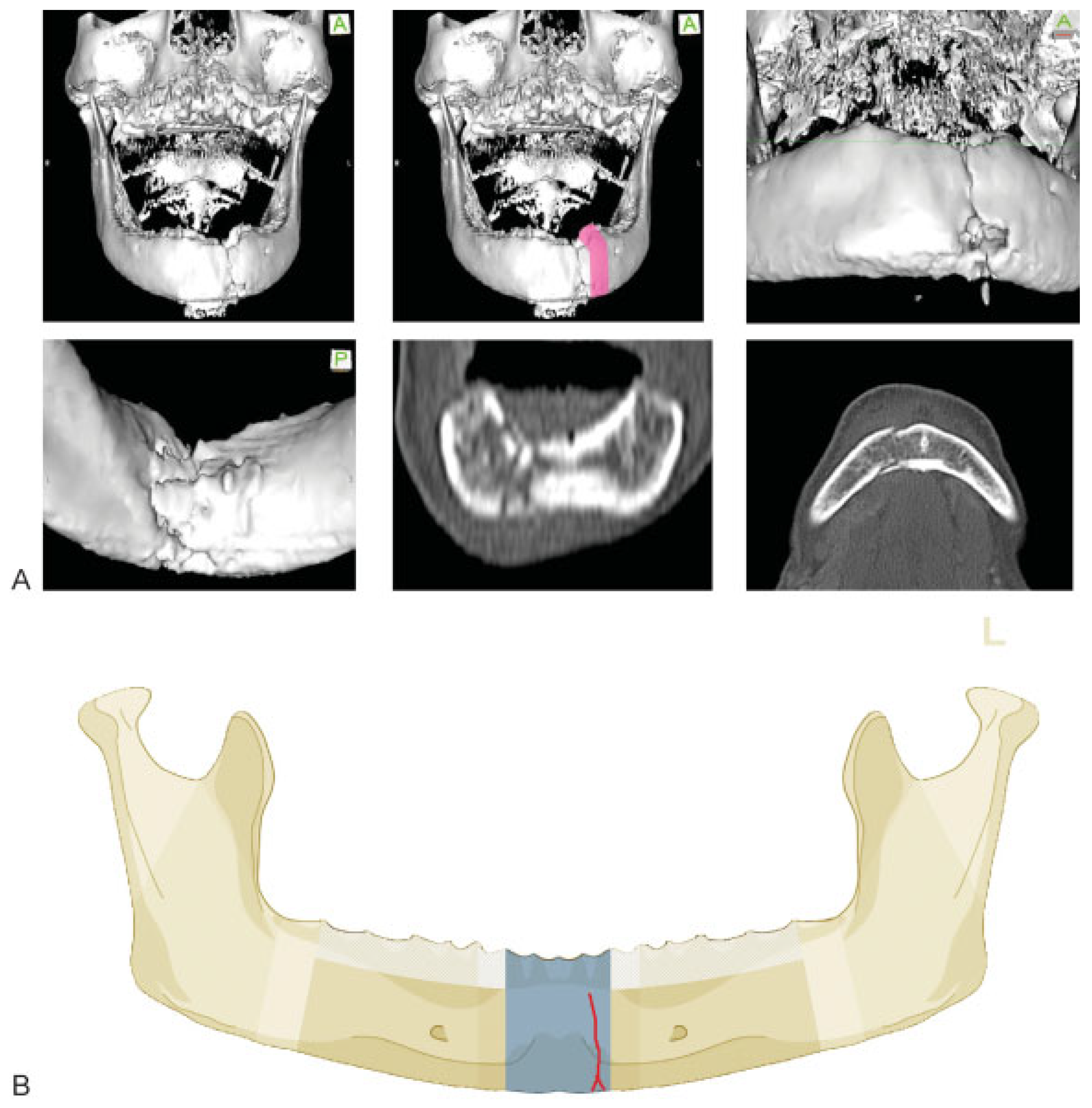
Symphysis/Parasymphysis Region

The symphysis/parasymphysis region is the single central unit of the mandibular arch. Its lateral edges are determined by the roots of the lower canines and thus this region matches with the intercanine bone portion. For the purpose of this classification, we will refer to it as the symphysis region.
Two anterior transitional zones (numbered 1 in Figure 1) are defined along the contours of the canine roots as vertical strips in the width of the adjacent interdental spaces. In the case of an edentulous mandible, the anterior transitional zone is located ~5 mm (= width of a premolar) in front of the mental foramen. These anterior transitional zones are defined to facilitate the location of fractures within the symphysis region depending on their extension into these zones or across to an adjoining body region (Figure 2). If a fracture within the symphysis region extends into one ante-rior transitional zone without crossing it, the fracture is considered confined within the symphysis region.

Mandibular Body Region
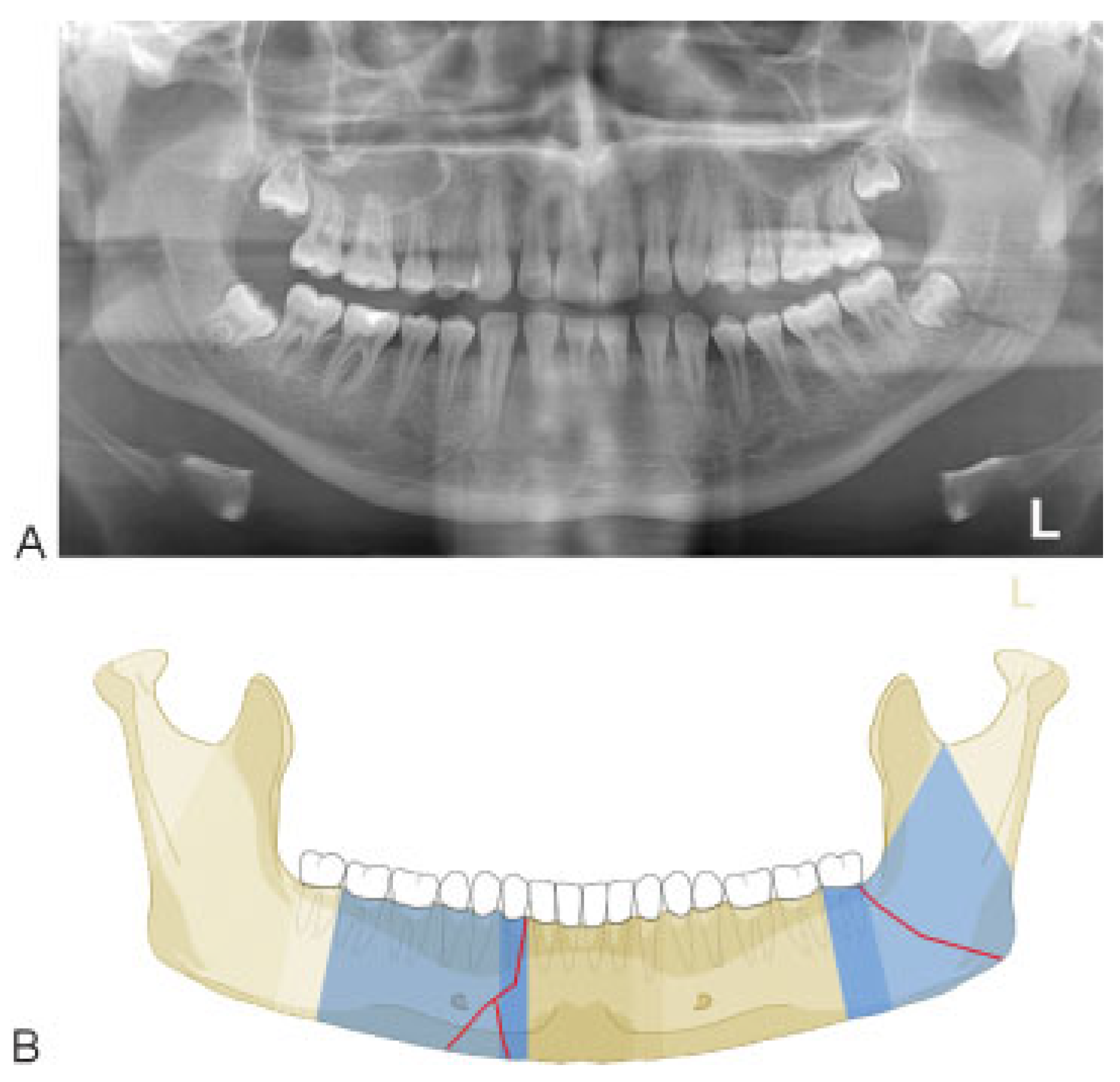
The mandibular body refers to each of the lateral bony regions between the canines and the angle. In the dentate mandible, the anterior edge of the mandibular body goes through the root of the lower canines. Thus, the anterior border of the body is congruent with the anterior transitional zone. A fracture line fully located within the anterior transitional zone is assigned to the respective body region; however, if it crosses into the symphysis region, it will be assigned also to that latter region (Figure 2). Two posterior transitional zones (numbered 2 in Figure 1) are defined along the outlines of the third molar roots as vertical strips in the width of the crown of the third molar. In the edentulous mandibular body, the posterior transitional zone must be placed in an approximate manner to incorporate the retromolar area. The vertical borders of the mandibular body are limited by the anterior and the posterior transitional zones.
The posterior transitional zones are considered when locating fractures within the area between body and the angle/ramus region. A fracture line in a body region extending into the posterior transitional zone is considered confined to the body region. No distinction is made in this classification here between anterior and posterior body fractures. All fracture courses within the mandibular body are equally classified as body fractures and check marked accordingly.

Angle/Ramus Region

The angle region and the ramus region excluding the condylar and the coronoid processes are merged into a single region. It has an irregular pentagonal shape and extends from a vertical line behind the third molar to the outer mandibular angle at the inferoposterior margin, to the mandibular notch and the bases of the condylar and the coronoid process superiorly.
The anterior boundary of the angle/ramus region is congruent with the posterior transitional zone; hence, the retromolar area is included within the angle/ramus region. A fracture line fully located within the posterior transitional zone is assigned to the angle/ramus region; however, if it extends into the body region, it is assigned to that region (Figure 2).
The superior boundary of the angle/ramus region has a gable-shaped configuration with two straight lines diverging from the middle of the mandibular notch. These lines delimit the base of the condylar process and the coronoid process, respectively. Fractures pertaining to the angle/ramus region extend from the inner angle of the mandible (third molar or retromolar area) or the anterior border of the ramus underneath the subcoronoid notch to the inferoposterior margin of the ramus (i.e., the outer angle).

Coronoid Process

The coronoid (muscular process) is the insertion site for the temporal muscle. The posterior concave border of the sharptipped triangular coronoid bone plate coincides with the anterior arc of the mandibular notch. The convex anterior crescent-shaped edge of the coronoid ends in the subcoronoid indentation. The base of the coronoid process corresponds to a line passing from the mandibular notch to the subcoronoid indentation.
The coronoid is regarded as fractured only if the coronoid is fully separated from the mandibular ramus. Even if the course of the fracture line does not sharply adhere to the boundaries of the coronoid and runs inferiorly into the adjacent angle/ramus region, it is still accounted as a coronoid process fracture.

Condylar Process

The condylar process is a major region comprising the base, neck, and head subregions. The borderline between the base of the condylar process and the adjacent angle/ramus is oblique and runs inferiorly and posteriorly from the lowest point of the mandibular notch to the masseteric tuberosity notch. [6] In a condylar process fracture, the bony continuity may be lost along this borderline to the ramus; however, if a fracture line exits the posterior margin of the ramus below the masseteric tuberosity notch, the fracture is allotted to the angle/ramus region. A more detailed description of the subregions of the condylar process follows in a separate Level 3 tutorial article fractures in this area. [6]

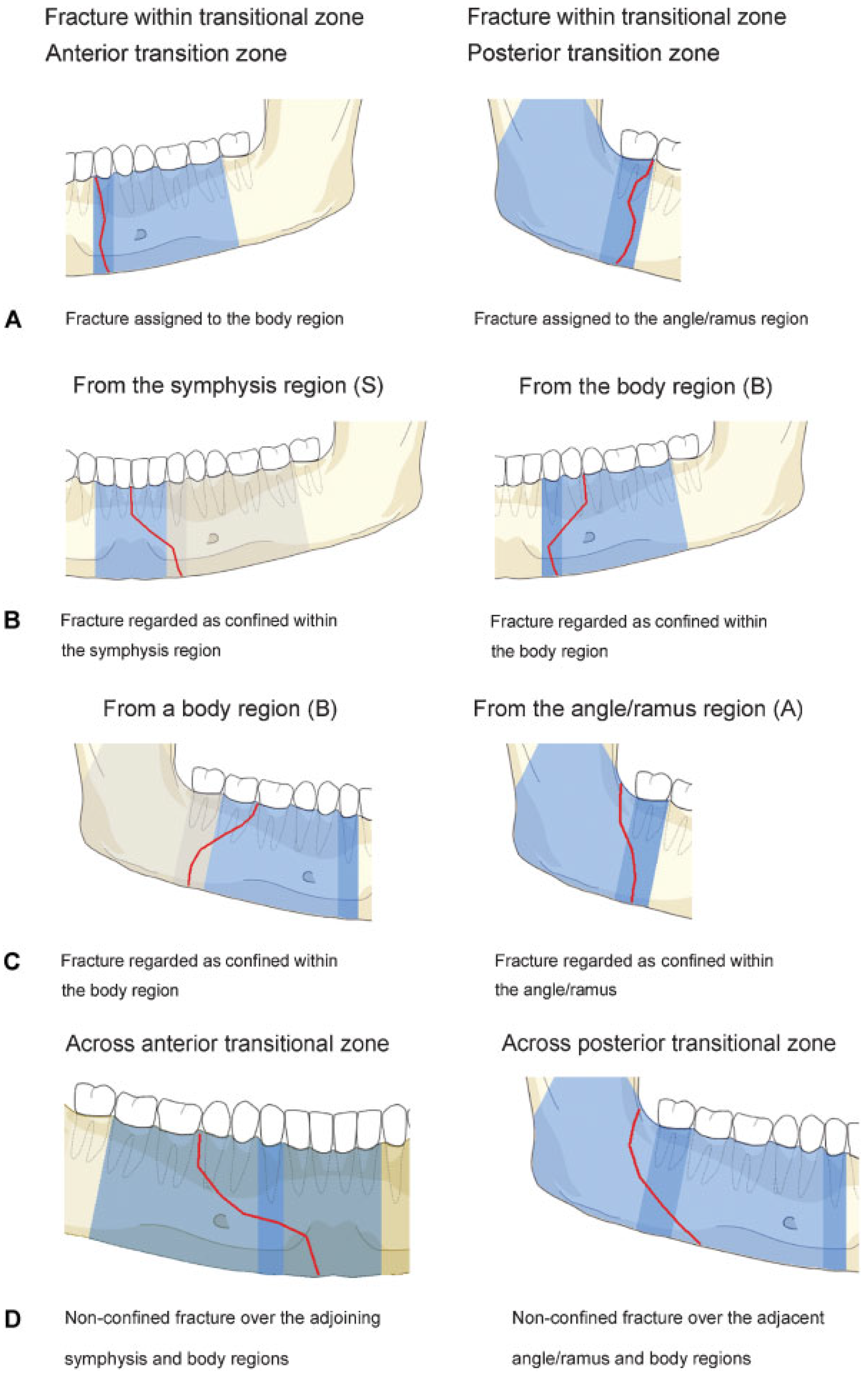
Confinement—Fractures Located within Anatomical Regions

Two fracture patterns are discerned with regard to their anatomical location within regions:
  • • “Confined” fracture pattern: the fracture, irrespective of its morphology, remains within an anatomical region (including a transition zone) and does not extend into an adjoining region across a transition zone.
  • • “Nonconfined” fracture pattern: the fracture crosses at least one transition zone and may extend over one or more adjoining region.

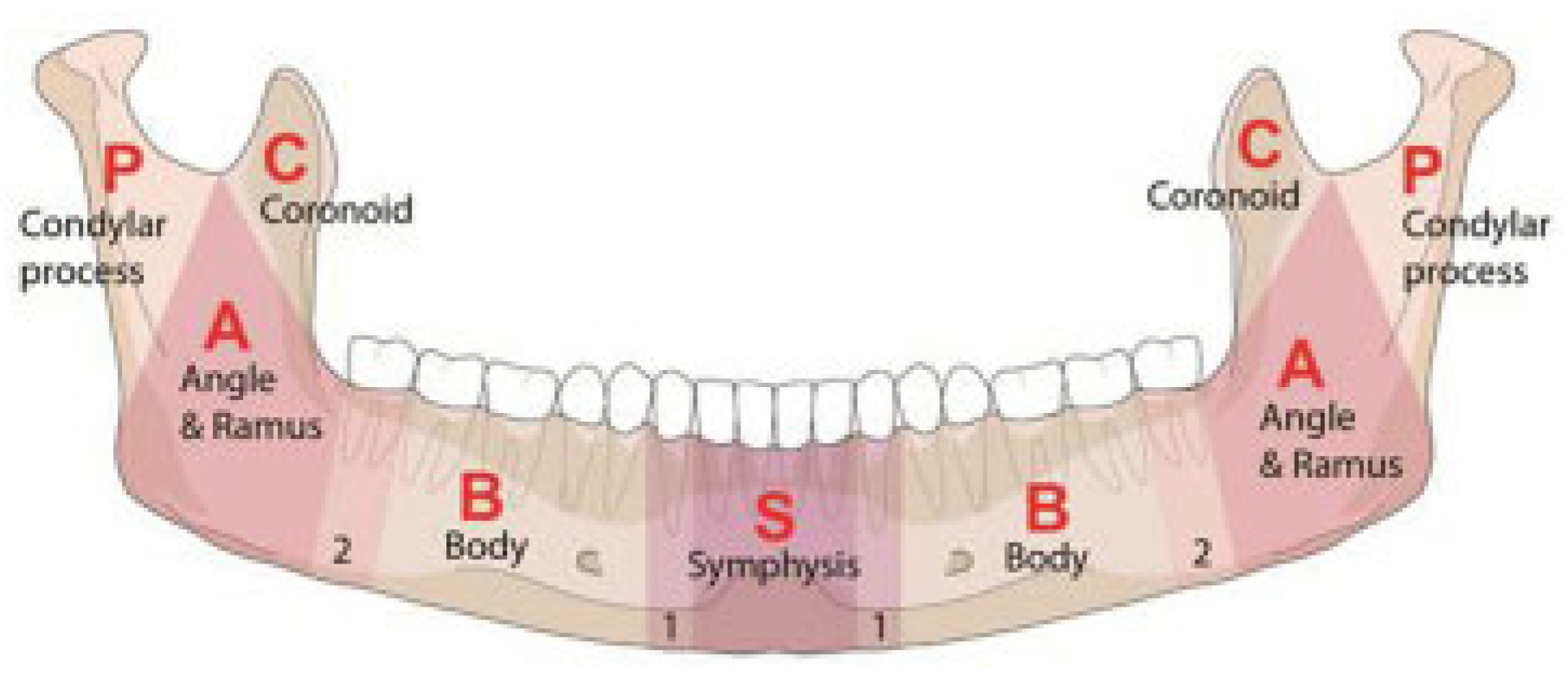
Fracture Coding and Topographical Distribution

According to the general scheme of the AO/OTA classification system, [7] craniomaxillofacial fractures are assigned with the one-digit code 9. In the CMF system, fractures of the mandible are identified with the two-digit code 91. [1] In coding the fractures according to their location in the level 2 system, each fractured region is identified by a letter (Figure 1):
  • S = Symphysis/parasymphysis
  • B = Body
  • A = Angle/ramus
  • C = Coronoid process
  • P = Condylar process
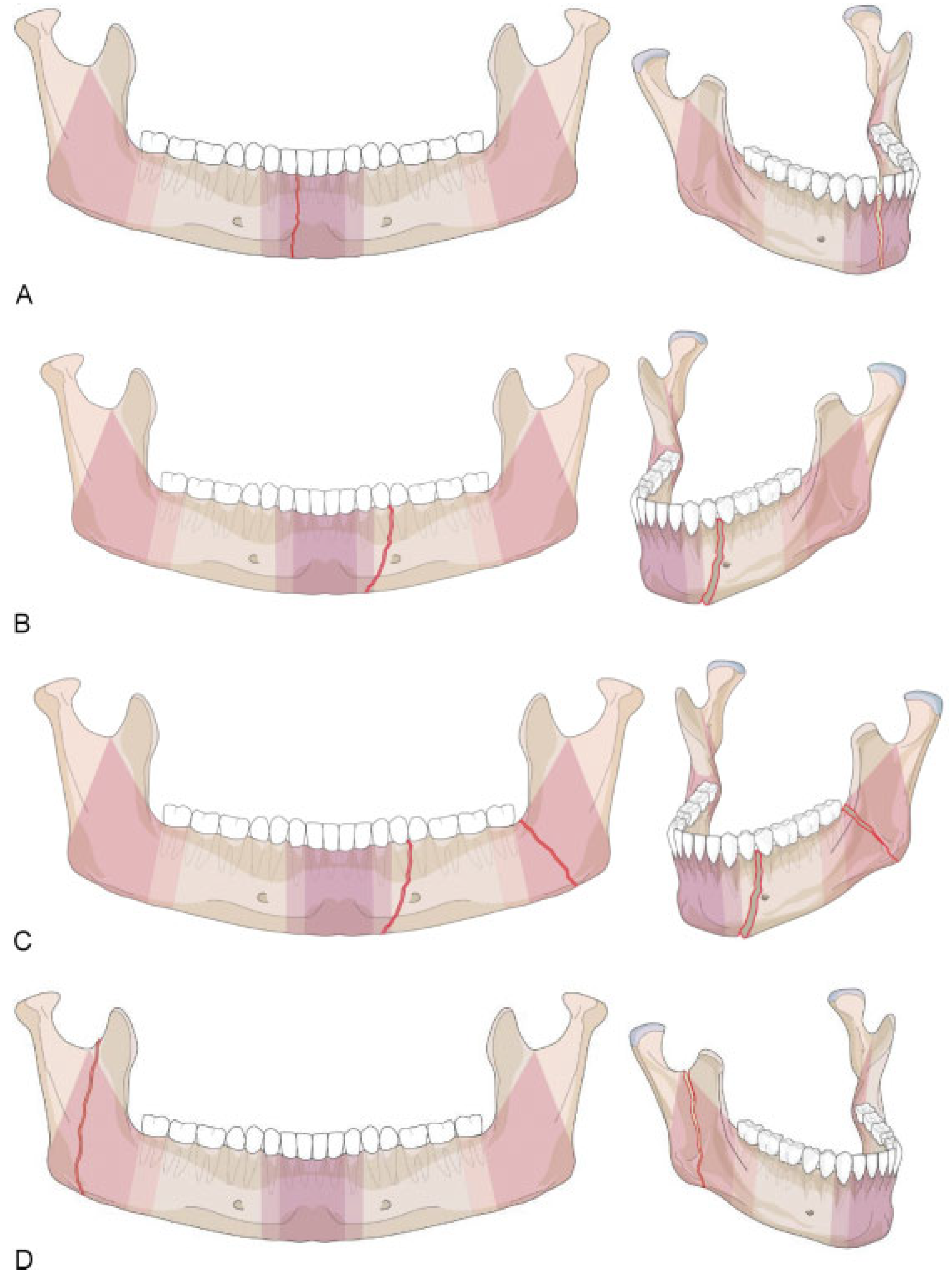
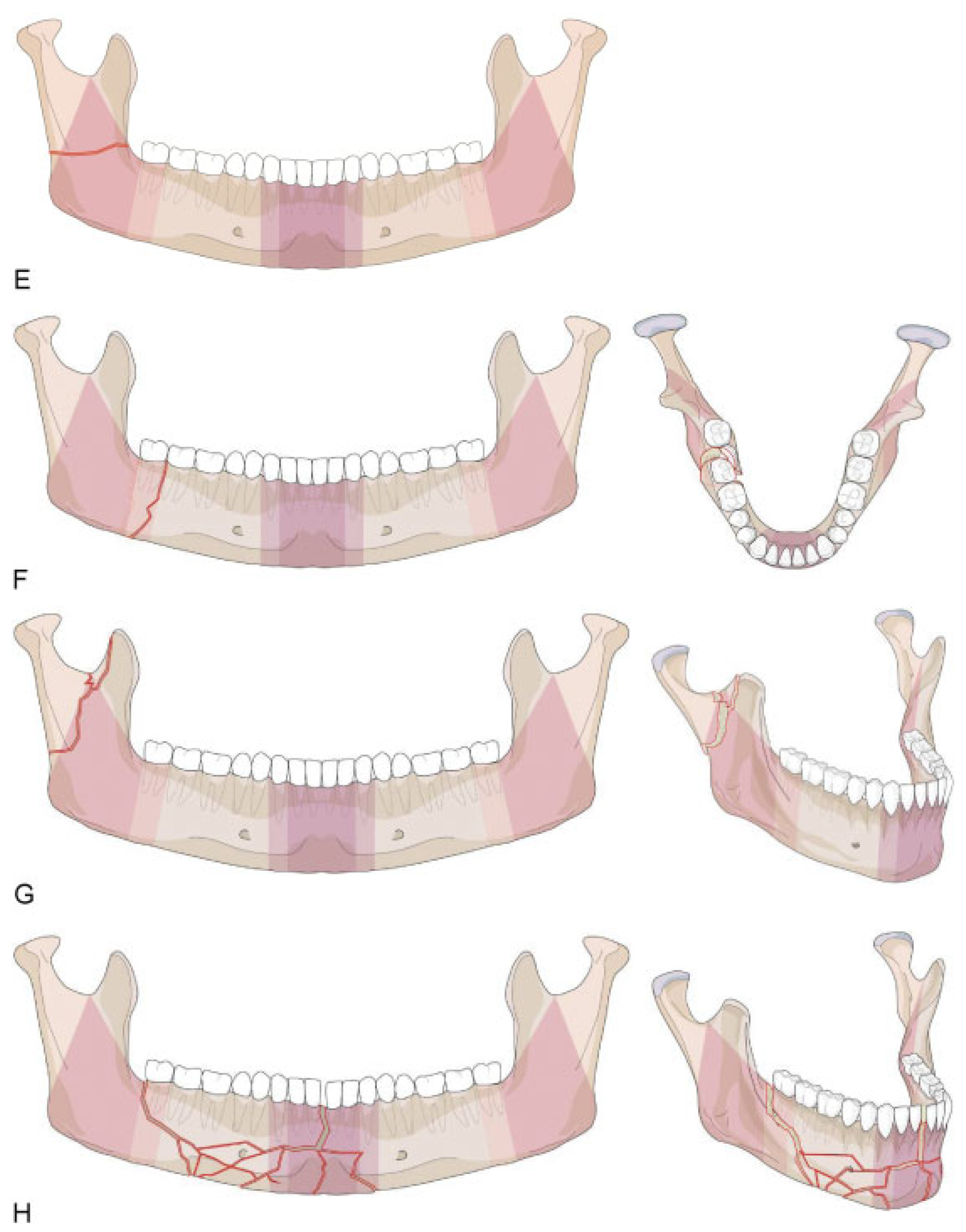
The letters specifying the involved regions are added after the initial 91. The regions are coded in the order from the patient’s right side to the patient’s left side. In the overall fracture code, the small letter “m” (abbreviation for “middle”), or the letter “S” if the symphysis region is fractured, marks the limit between the two sides. Hence, letters specified before and after the “m” or “S” refer to the patient’s right and left side, respectively. A hyphen sign “-” is inserted in between region letters to indicate that a fracture extends into an adjoining region (nonconfined). The hyphen is replaced by a point “.” between two letters to indicate the related regions are involved with separate fractures.

Case Examples

In a series of three case examples, we illustrate the coding of a fracture confined within the symphysis (Figure 3), a doublefracture pattern confined within body and angle/ramus regions (Figure 4), and a nonconfined fracture located within the symphysis and one body region (Figure 5). A range of additional fracture patterns is presented online in a special case appendix as electronic supplement (www.cmf.aofoundation.org/classification).
This coding system allows description of the topographical distribution of fractures, such as unilateral or bilateral fracture patterns. In accord with the areas of mechanical weakness in the mandible, there are some typical topographic fracture site combinations. Fractures in the anterior arc are frequently associated with posterior fracture sites in the angle or in one or both condylar processes. Typical examples for bilateral double fracture are symphysis or body fractures conjoined with a contralateral condylar process fracture (Figure 6A). Another common bilateral fracture is a symphysis fracture combined with an angle/ramus region fracture (Figure 6B). It should be noted that a double unilateral fracture may occur within the body or the ramus/angle region (Figure 6C); in the level 2 system, such a pattern is documented as one fracture. In the level 3 system describing the morphol-ogy of the fracture, it is described as a severe fragmentation pattern. [2] Other fracture patterns are presented in Appendix A.

Discussion

There are no natural lines in the mandible allowing for a clearcut distinction of anatomic regions, therefore / or/ that is why a uniformly agreed upon anatomic or surgical terminology detailing the interregional borders and margins is missing. A topographic classification of the mandible fractures requires the implementation of a conclusive visual framework in combination with written definitions to enable a reliable assignment of injuries.
For the anatomical location of fractures, a set of vertical borderlines divides the mandibular arch into three regions: the symphysis and the body on the left and on the right. Each ramus also consists of three regions (angle/ramus, coronoid process, and condylar process); hence, the entire mandible is conceptualized into nines principal topographic regions.
Existing classification schemes have sorted mandible fractures under multiple aspects by topographic location, dental occlusion and state of dentition, course, number and overall pattern of fracture lines, relation to masseter, pterygoid muscle sling, displacement of bone ends, dislocation of condylar head out of the fossa, fragmentation and comminution, and bone atrophy or loss and associated soft tissue injuries within the overlying oral mucosa and/or through the facial skin. [8,9,10]
For this level 2 mandible fracture classification, only former attempts with topographic implications will be discussed in a chronological literature review (Table 1).
Topographic classifications of mandible fractures are com-monly used to conduct epidemiologic surveys and to describe the predilection in the anatomical regions depending on the etiology (i.e., motor vehicle accident vs. physical assault) and gender. [11,12,13,14,15,16]
Rowe and Killey, in their textbook, [17,18] suggested a division of mandibular fracture sites into two main categories: (1) alveolar fractures not involving the basal bone and (2) fractures involving the basal bone. The great majority of fractures were attributed to the second category. Single unilateral basal bone fractures were further subdivided into six regions (symphysis, canine, angle and body combined, ramus, coronoid, condyle). Fracture combinations within any of these regions were distinguished into double unilateral, bilateral, and multiple fractures. Curiously enough the borderlines of the topographic regions were neither noted in writing nor schematically specified. Instead of exactly indicating the involved area, representative fracture lines passing through each of the suggested regions were demonstrated using plastic models, clinical photographs, or a variety of X-rays.
Huelke et al, [19,20] in their studies on 319 case histories of mandibular fractures from Ann Arbor, Michigan, reported on 4 major locations: (1) chin fractures, between the mental foramina or the corners of the mouth, (2) angle–body, fractures located between the gonial angle and the mental foramen, (3) subcondylar, at the neck of the mandible, and (4) “other” fractures, comprising the ramus, alveolar bone alone, and the coronoid process. The angle–body region in this approach is of extensive width and offers a zone for plenty of fracture assignments. In contrast, the large and undifferentiated category “other fracture” was used, because there were no fractures in the ramus or coronoid occurring in the study sample. Despite the somewhat coarse and subjective categorization, the introduction of anatomic landmarks independent of the presence of teeth was a novelty. Apart from the mental foramen, a line anterior to the ramus downwards to the mandibular base was applied to delineate the regions in edentulous subjects.
Dingman and Natvig [8] have classified seven regions for fracture allocation (symphysis, body, alveolar process, angle, ramus, condyle process, coronoid process) with a cartographic mapping of the sites displayed on a hemimandible in their early textbook article. The roots of the lower canines and the borderlines of the angle region are the essential markers to delineate these regions. The angle region or the surgical angle conforms to a triangular area bounded by the anterior margin of the masseter muscle and by a line from the retromolar trigone to the “posterior-superior attachment of the masseter to the ramus.” The body region of the mandible spans between the canine and the anterior boundary of the angle accordingly. The socalled “symphysis” refers to the intercanine area of the mandible as adopted in this AO level 2 mandible fracture classification system. The ramus region is bounded by the superior demarcation of the angle to two lines forming an apex at the sigmoid notch. [8]
The Dingman and Natvig classification and also the Rowe and Killey classification are still the most popularly used schemes around the world today. [21] A major difference between them is in the size of the angle region being notably wider in the Rowe and Killey classification due to a combination with the body region. With the aim to determine the “weak” regions of the mandible with regard to the state of dentition, Halazonetis [22] used elements of both these classifications as well as Huelke landmarks [20] to match identical regions in dentulous and edentulous jaws.
Spiessl and Schroll [10] added the glenoid fossa which is part of the temporal bone to a first classification layout which essentially was adopted from Rowe and Killey, [17] as well as Dingman and Natvig. [8]
Kelly and Harrigan [23] adhered to the prototypical mandibular divisions of former classifications; however, they devised an arbitrary scheme of vertical or oblique fracture line courses and simply defined their interdental origin for their allocation.
Krüger [23] devised a fracture classification and terminology that entered into the AO CMF Manual later years [24,25] with the fracture sites borrowed from Dingman and Natvig [8] again.
Based on the preparatory work of Grätz [26] the acronym FLOSA was introduced by Spiessl [9] to feed the numerous features of mandibular fractures into a single concise formula (F = frac-ture category; L = localization/fracture site; O = occlusion, S = soft tissue involvement; A = associated fractures). A new site-specific terminology (Table 1) was created to label the anatomic regions, which essentially reproduced the Dingman and Natvig scheme as previously mentioned. [10] The allocation of a fracture line to a region was determined by its course in the basal zone of the mandible, irrespective of the dentoalveolar or interdental pathway.
In a computer-based coding system of craniofacial fractures, Cooter and David [27] defined each hemimandible as one of 10 major unilateral anatomical zones and divided it ostensibly into 7 subzones (Table 1). Accounting for embry-ological, developmental, biomechanical, etiopathogenic, and epidemiological background knowledge, Gola et al [28] remodeled existing classifications with the claim to preclude terminological imprecision and to better comply the borderlines between the regions with the variation in anatomic and clinical reality of mandibular fractures. They designed straight “interregional” lines with angulation both in the frontal and the sagittal plane. The lines pass through dental crowns (canine and third molar), bony landmarks (mental foramen, preangular, and sigmoid notch), or the margins of the masseter muscle. In the sagittal plane, the three lines through the canine and mental foramen (= symphysis–ramus boundary), from the retromolar fossa to the preangular notch or the anteroinferior masseter insertion, respectively (= “interbody–ramus” border), and from the sigmoid notch to the posteroinferior masseter insertion (= “interangle–condyle” demarcation) are arranged in parallel. Thus, in the edentulous mandible the interregional separation lines can be elegantly installed in a posterior–anterior fashion with these parallels just touching bony landmarks. Likewise, in this level 2 proposal the angle is regarded as single central constituent of the anatomical ramus with its upper borders shifted toward the condylar and coronoid base, resulting in a pentagonal shape. A separate surgical ramus region is not demarcated. In the first approach to establish a mandibular fracture severity score, Joos et al [29] attributed a value ranging from 0 to 3 points depending on the anatomic location (for details, see Table 1) into the summation of the total score with a possible maximum of 15 points. The angle/ramus was grouped as a single anatomic constituent with three points as the highest location score.
A reappraisal of Spiessl FLOSA classification equipped with surplus features (T = teeth, D = dislocation, I = infection) was proposed by Pankratov and Robustova [30] but ended up in information overload and inapplicability for routine purposes.
In a study on the comparative performance of helical CT versus panorex tomography, Roth et al [4] relied on an anatomical diagram of the mandibular regions to identify the fracture location. The borders of the topographical division into regions were not described.
With the aim to set up an improved “Mandible Injury Severity Score” (MISS), Shetty et al [31] made use of most of the individual FLOSA components. [9] Instead of recording associated fractures (A), they included measures for infection (I) and interfragmentary displacement (D) modifying the previous acronym into FLOSID. The relative impact on the clinical outcome of each individual component was multiplied by a corresponding weighting factor and the resulting points were added to a summary score rating the injury severity. Apart from a graphical scheme displaying the anatomic regions similarly to Spiessl proposal, the borderlines were not verbally specified. The interregional demarcations of this scheme are self-explaining if they extend from interdental spaces but they appear at random in the anatomical ramus due to the lack of definite landmarks. A valuable remark is made, on where to assign fractures which extend across two adjoining anatomic regions. Referring to Spiessl “determining zone,” such fractures are suggested to be allocated to the basal region that is predominantly involved.
Follmar et al [32] get back to established facial fracture classifications to offer an organized uniform reporting system which seeks to avoid redundancies and improve communication. A color-marking superimposed on the photograph of a macerated mandibula is used to specify the topographical regions; their borderlines were defined with regard to interdental spaces (Table 1).
A classification scheme in accordance with the AO/ASIF “Tripartite”—principle used in long bones and pelvis (see Audigé et al [1] in this Supplement)—was reported by Buitrago-Téllez et al. [33] It was exclusively based on imaging analysis and divided the mandible into two vertical compartments (anatomical ramus right/left), two lateral horizontal compartments (mandibular body and dentoalveolar process right/ left), and one central compartment (symphysis and two parasymphyseal regions). A region-specific 3 × 3 × 3 grid of categories (e.g., displacement type, multifragmentation, single fracture vs. fracture combinations) and specifications (e.g., fracture pattern—basal triangle, separate fracture lines, atrophy of the alveolar process, condylar head dislocation out of the fossa) was then imposed onto each of the three compartments and transferred into a single fracture formula. While this ambitious proposal consisting of 75 items and the possible permutations thereof was rather complex and memo-technically demanding, the separation lines between the compartments were kept easy and skimped. The boundary between the central and the horizontal compartments was placed on a vertical line through the apices of the canine roots. A vertical line in the interdental space between the second and third molar was suggested for the division of the horizontal from the vertical compartments. Formal instructions on how to split the compartments into their subunits were not mentioned.
Carinci et al [34] came up with a Facial Fracture Severity Score (FFSS) “scoring” method to stage mandibular fractures. Besides the anatomic sites (Table 1), they essentially accounted for the type (incomplete/complete) and number of fracture lines in the alveolar process and/or the basal arch (single/double/triple) to indicate the severity stage.
Catapano et al [35] styled an “FFSS” for the comprehensive documentation of panfacial fractures applying 41 anatomical regions on the face and quantifying the severity in terms of a disruption grade within each of these regions. The extent of the regions in the mandible basically resembles FLOSA loca-tions [9] and MISS taxonomy [31] but the size ratio of the angle and the ramus region was altered in favor of the latter (Table 1). The angle region was confined to an area inferior to the third molar, whereas the anteroinferior border of the ramus lies just posterior to the lower wisdom tooth. The superior boundary of the ramus region corresponds to a horizontal line passing through the lowest point of the mandibular notch as a tangent. In their specific classification of mandibular condylar process fractures, Loukota et al [37] already had referred to the same line as reference to distinguish between fracture of the condylar neck and the condylar base (see Neff et al [6] in this issue).
Besides the typical elements, this brief chronology of the existing mandibular fracture classification systems shows inconsistencies and shortcomings of the evolving concepts to this day. The topography of the anatomic regions has usually been referred to the hemimandible, whereas more recent classification attempts look at the entire mandible as a single block [28,31,35] (Table 1). This level 2 proposal also regards the entire mandible, viewed in panorama style, to improve comprehensiveness, to preclude mix-up of the right and left mandibular halves, and to allow for a symphysis region.
Two of four topographical regions of the mandible, respectively, continuously attracted particular attention: one, the turning points of the U-shaped mandibular arch from the lateral limbs into the anterior partition in the axial plane and, second, the corners between the lateral horizontal limbs and the vertical posterior extensions in the sagittal plane, known as the angle region or the surgical angle of the mandible.
Further increased by the long canine roots and the lower wisdom teeth, both regions are weak spots22,38,39 or “breakpoints” biomechanically, where the majority of fractures usually occur. However, the determination of the according regions and borderlines has been a constant source of discrepancies. The lower canines, the mental foramen, or even a combination of both [28] were used to delineate the symphysis to make up an intercanine or interforaminal unit (Table 1). In anatomical/embryological terms, the symphysis refers to the midline only; however, in this proposal it should be understood that it includes the left and right parasymphyseal area. A true symphysis fracture might be conceived as a vertical linear fracture in the midsagittal plane of the anterior mandible reminding to infantile development status of the mandible, when it consisted of a pair of bones with a median fibrous union. Yet, no difference is made in the level 2 between median, paramedian, or any alternative fracture course within the symphysis, because only the region accommodating a single or a multiple fractures is denominated as a whole. In level 2, the symphysis region corresponds to the intercanine area in between the two anterior transitional zones.
The body region spreads from the anterior to the posterior transitional zone, which is the connection to the angle/ ramus region. The extent and shaping of the angle region were subject to substantial variations (see Table 1 and Figure 7). In the initial classification attempts, the angle conformed to a triangular-shaped area and was spaced apart from the ramus region; later, it was merged with the body or with the ramus region to a singular unit. In the past, the borders of these regions were hardly ever defined precisely in writing or text form. Instead, it was relied on illustrative schemes and a sign language. So it is not surprising that even key papers on the osteosynthesis in the mandibular angle go without sparing a word to define the involved region. [39,40,41,42,43,44,45]
In this level 2 classification attempt, the angle and the ramus region are incorporated into a sole large unit, comparable to Gola et al. [28] The anterior (and inferior) boundary of this angle/ramus region runs almost vertically from the distal aspect of the third molar to the inferior margin of the mandible. The gable-shaped top end of the region coincides with the base of the condylar process and the base of the coronoid process, with both borderlines defined through anatomical landmarks (mandibular notch, masseteric tuberosity notch, subcoronoid indentation).
The transitional zones introduced in this level 2 proposal represent cross-border areas between the adjoining regions of the mandibular arch. They are located in the two vulnerable zones of the mandibular arch already described. A transitional zone has the function of a corridor, adding to the spatial extent of adjacent regions following clear rules to allocate fractures (Figure 2).
While a fracture course confined within a transition zone is allocated to the adjoining posterior region, fractures crossing a transitional zone are allocated to both juxtaposed regions. Spiessl’s basal “determining zone” along the basal border [9] can be regarded as a precursor of the “transitional zone” concept in this level 2 system. In contrast to Spiessl’s horizontally oriented ribbon-like zone, the transitional zones are vertical strips in the width of the lower canine and the third molar. Retrospectively, it may be assumed that Spiessl intended to avoid a reference to the teeth, since the state of dentition and the degree of alveolar atrophy can vary. Interestingly, most of the existing classifications make use of the dentition to determine the anatomic distribution of fracture line courses. However none of the classifications had a design to record the actual tooth condition at all or in particular detail, just as this level 2.

Concluding Note

The proposed system is simple enough for daily routine; however, it allows description of manifold fractures. The occurrence of single, double, triple, or multiple fractures is well portrayed in the coding. A pure topographical classification system ultimately will not be suitable to portray the diversity and the overall complexities of a mandibular trauma. Nevertheless, the allocation of a fracture to an anatomic region or site is deemed the initial step prior to more refined ways of analysis and orderly documentation as offered in the subsequent level 3 article. [2]

Acknowledgments

This CMF classification project was funded by the AO Foundation and its AOCMF Specialty. Illustrations were prepared by AO Education (publishing) by Jecca Reichmuth and her colleagues. The authors are grateful to all surgeons (as listed Audigé et al [1] in this issue in alphabetic order) who participated in the successive classification sessions and provided their fruitful support in the development and validation of this mandibular fracture classification system.

Appendix A. Additional level 2 coding examples of mandibular fractures

Figure A1. (A) Level 2 code: 91 S. Fracture in the symphysis/parasymphysis subdivision. (B) Level 2 code: 91 m.B. Isolated body fracture. (C) Level 2 code: 91 m.B-A. Unilateral double mandibular fracture: Anterior body and angle/ramus region. (D) Level 2 code: 91 A.m. Isolated/single fracture in the mandibular angle/ramus region (vertical). (E) Level 2 code: 91 A.m. Isolated/single fracture in the mandibular angle/ramus region (horizontal). (F) Level 2 code: 91 A.m. Isolated/single fracture in the mandibular angle/ramus region (vertical in transition zone). (G) Level 2 code: 91 P.m. Isolated/single condylar base fracture on the right side with extension into the coronoid. There is however no coronoid fracture. (H) Level 2 code: 91 B-S. Fracture with contiguous involvement of two subdivisions; the body on the right and the symphysis subdivision. The right angle is not included, since the fracture is centered in the body with a single line terminating within the posterior transition zone. (I) Level 2 code: 91 C.S-B. Coronoid fracture on the right side combined with a contiguous fracture in the symphysis subdivision and body region on the left side (i.e. a non-cofined fracture). (J) Level 2 code: 91 P.S.P. Triple mandible fracture: symphysis and condylar process bilaterally. (K) Level 2 code: 91 A.m.B. Bilateral double mandible fracture: Anterior body and contralateral angle/ramus. (L) Level 2 code: 91 S. Bilateral double mandible fracture at the outer ends of the symphysis subdivision.
Cmtr 07 00006 g0a1aCmtr 07 00006 g0a1bCmtr 07 00006 g0a1c

References

  1. Audigé, L.; Cornelius, C.P.; Di Ieva, A.; Prein, J.; CMF Classification Group. The first comprehensive AO classification system for fractures of the craniomaxillofaxial skeleton: rationale, methodological background, developmental process and objectives. Craniomaxillofac Trauma Reconstr 2014, 7 (Suppl 1), S6–S14. [Google Scholar]
  2. Cornelius, C.P.; Audigé, L.; Kunz, C.; et al. The comprehensive AOCMF classification system: mandible fractures - level 3 tutorial. Craniomaxillofac Trauma Reconstr 2014, 7 (Suppl 1), S31–S43. [Google Scholar]
  3. Buitrago-Téllez, C.H.; Cornelius, C.P.; Prein, J.; et al. The comprehensive AOCMF classification system: radiological issues and systematic approach. Craniomaxillofac Trauma Reconstr 2014, 7 (Suppl 1), S123–S130. [Google Scholar] [CrossRef]
  4. Roth, F.S.; Kokoska, M.S.; Awwad, E.E.; et al. The identification of mandible fractures by helical computed tomography and panorex tomography. J Craniofac Surg 2005, 16, 394–399. [Google Scholar] [CrossRef] [PubMed]
  5. Anatomica, T. International Anatomical Terminology, 1st ed.Thieme Medical Publishers: New York, NY, 1998. [Google Scholar]
  6. Neff, A.; Cornelius, C.P.; Rasse, M.; et al. The comprehensive AOCMF classification system: condylar process fractures - level 3 tutorial. Craniomaxillofac Trauma Reconstr 2014, 7 (Suppl 1), S44–S58. [Google Scholar]
  7. Marsh, J.L.; Slongo, T.F.; Agel, J.; et al. Fracture and dislocation classification compendium - 2007: Orthopaedic Trauma Association classification, database and outcomes committee. J Orthop Trauma 2007, Suppl), S1–S133. [Google Scholar]
  8. Dingman, R.O.; Natvig, P. Surgery of Facial Fractuers; WB Saunders: Philadelphia, PA, 1964. [Google Scholar]
  9. Spiessl, B. Spiessl, B., Ed.; AO classification of mandibular fractures. In Internal Fixation of the Mandible-A Manual of AO/ASIF Principles, 2nd ed.; Springer Verlag: Berlin, Heidelberg, New York, London, Paris, Tokyo, 1989. [Google Scholar]
  10. Spiessl, B.; Schroll, K. Nigst, H., Ed.; Unterkieferfrakturen, Vorbemerkungen. In Spezielle Frakturen-und Luxationslehre, 1st ed.; Thieme Verlag: Stuttgart New York, 1972; pp. 102–107. [Google Scholar]
  11. Kelly, D.E.; Harrigan, W.F. A survey of facial fractures: Bellevue Hospital, 1948-1974. J Oral Surg 1975, 33, 146–149. [Google Scholar]
  12. Bormann, K.H.; Wild, S.; Gellrich, N.C.; et al. Five-year retrospective study of mandibular fractures in Freiburg, Germany: incidence, etiology, treatment, and complications. J Oral Maxillofac Surg 2009, 67, 1251–1255. [Google Scholar] [CrossRef]
  13. Meaders, R.A.; Sullivan, S.M. The development and use of a computerized database for the evaluation of facial fractures incorporating aspects of the AAOMS Parameters of Care. J Oral Maxillofac Surg 1998, 56, 924–929. [Google Scholar]
  14. Olson, R.A.; Fonseca, R.J.; Zeitler, D.L.; Osbon, D.B. Fractures of the mandible: a review of 580 cases. J Oral Maxillofac Surg 1982, 40, 23–28. [Google Scholar] [CrossRef]
  15. Ellis, E., III; Moos, K.F.; el-Attar, A. Ten years of mandibular fractures: an analysis of 2,137 cases. Oral Surg Oral Med Oral Pathol 1985, 59, 120–129. [Google Scholar] [CrossRef] [PubMed]
  16. Chrcanovic, B.R.; Abreu, M.H.; Freire-Maia, B.; Souza, LN. 1,454 mandibular fractures: a 3-year study in a hospital in Belo Horizonte, Brazil. J Craniomaxillofac Surg 2012, 40, 116–123. [Google Scholar] [PubMed]
  17. Rowe, N.L.; Killey, H.C. Fractures of the facial skeleton. Williams & Wilkins: Baltimore, 1968. [Google Scholar]
  18. Rowe, N.L.; Killey, H.C. General considerations and classification of mandibular fractures; Williams & Wilkins: Baltimore, 1955. [Google Scholar]
  19. Huelke, D.F.; Burdi, A.R.; Eyman, C.E. Association between mandibular fractures and site of trauma, dentition and age. J Oral Surg Anesth Hosp Dent Serv 1962, 20, 478–481. [Google Scholar] [PubMed]
  20. Huelke, D.F.; Burdi, A.R.; Eymen, C. Mandibular fractures as related to site of trauma and state of dentition. J Dent Res 1961, 40, 1262–1266. [Google Scholar]
  21. Luyk, N.H.; Ferguson, J.W. The diagnosis and initial management of the fractured mandible. Am J Emerg Med 1991, 9, 352–359. [Google Scholar] [CrossRef]
  22. Halazonetis, J.A. The ‘weak’ regions of the mandible. Br J Oral Surg 1968, 6, 37–48. [Google Scholar]
  23. Krüger, E. Krüger, E., Schilli, W., Eds.; Mandibular fractures, 1. Classification, diagnosis and fundamentals of treatment. Quintessence Publishing Company: Oral and Maxillofacial Traumatology. Chicago, 1982; pp. 211–223. [Google Scholar]
  24. Prein, J. Manual of Internal Fixation in the Cranio-Facial Skeleton. Springer: New York, NY, 1998. [Google Scholar]
  25. Schilli, W.; Stoll, P.; Bähr, W.; Prein, J. Prein, J., Ed.; Mandibular fractures. In Manual of Internal Fixation in the Cranio-Facial Skeleton; Springer: New York, NY, 1998; pp. 86–87. [Google Scholar]
  26. Grätz, K. Eine neue Klassifikation zur Einteilung von Unterkiefer- frakturen Universität Basel; 1986. 1986.
  27. Cooter, R.D.; David, D.J. Computer-based coding of fractures in the craniofacial region. Br J Plast Surg 1989, 42, 17–26. [Google Scholar] [CrossRef]
  28. Gola, R.; Cheynet, F.; Carreau, J.P.; Amrouche, M. Proposal of a new topographic classification of mandibular fractures [in French]. Rev Stomatol Chir Maxillofac 1996, 97, 59–71. [Google Scholar]
  29. Joos, U.; Meyer, U.; Tkotz, T.; Weingart, D. Use of a mandibular fracture score to predict the development of complications. J Oral Maxillofac Surg 1999, 57, 2–5, discussion 5–7. [Google Scholar] [CrossRef]
  30. Pankratov, A.S.; Robustova, T.G. A classification of mandibular fractions [in Russian]. Stomatologia (Mosk) 2001, 80, 29–32. [Google Scholar]
  31. Shetty, V.; Atchison, K.; Der-Matirosian, C.; et al. The mandible injury severity score: development and validity. J Oral Maxillofac Surg 2007, 65, 663–670. [Google Scholar] [CrossRef] [PubMed]
  32. Follmar, K.E.; Baccarani, A.; Das, R.R.; et al. A clinically applicable reporting system for the diagnosis of facial fractures. Int J Oral Maxillofac Surg 2007, 36, 593–600. [Google Scholar] [CrossRef]
  33. Buitrago-Téllez, C.H.; Audigé, L.; Strong, B.; et al. A comprehensive classification of mandibular fractures: a preliminary agreement validation study. Int J Oral Maxillofac Surg 2008, 37, 1080–1088. [Google Scholar] [CrossRef] [PubMed]
  34. Carinci, F.; Arduin, L.; Pagliaro, F.; et al. Scoring mandibular fractures: a tool for staging diagnosis, planning treatment, and predicting prognosis. J Trauma 2009, 66, 215–219. [Google Scholar] [CrossRef] [PubMed]
  35. Catapano, J.; Fialkov, J.A.; Binhammer, P.A.; et al. A new system for severity scoring of facial fractures: development and validation. J Craniofac Surg 2010, 21, 1098–1103. [Google Scholar] [CrossRef]
  36. Loukota, R.A.; Eckelt, U.; De Bont, L.; Rasse, M. Subclassification of fractures of the condylar process of the mandible. Br J Oral Maxillofac Surg 2005, 43, 72–73. [Google Scholar] [CrossRef]
  37. Ichim, I.; Swain, M.V.; Kieser, J.A. Mandibular stiffness in humans: numerical predictions. J Biomech 2006, 39, 1903–1913. [Google Scholar] [CrossRef]
  38. Craig, M.; Bir, C.; Viano, D.; Tashman, S. Biomechanical response of the human mandible to impacts of the chin. J Biomech 2008, 41, 2972–2980. [Google Scholar] [CrossRef]
  39. Bell, R.B.; Wilson, D.M. Is the use of arch bars or interdental wire fixation necessary for successful outcomes in the open reduction and internal fixation of mandibular angle fractures? J Oral Maxillofac Surg 2008, 66, 2116–2122. [Google Scholar] [CrossRef]
  40. Ellis, E., III. Management of fractures through the angle of the mandible. Oral Maxillofac Surg Clin North Am 2009, 21, 163–174. [Google Scholar] [CrossRef]
  41. Fox, A.J.; Kellman, R.M. Mandibular angle fractures: two-miniplate fixation and complications. Arch Facial Plast Surg 2003, 5, 464–469. [Google Scholar] [PubMed]
  42. Gear, A.J.; Apasova, E.; Schmitz, J.P.; Schubert, W. Treatment modalities for mandibular angle fractures. J Oral Maxillofac Surg 2005, 63, 655–663. [Google Scholar] [PubMed]
  43. Haug, R.H.; Serafin, B.L. Mandibular angle fractures: a clinical and biomechanical comparison-the works of Ellis and Haug. Craniomaxillofac Trauma Reconstr 2008, 1, 31–38. [Google Scholar]
  44. Haug, R.H.; Peterson, G.P.; Goltz, M. A biomechanical evaluation of mandibular condyle fracture plating techniques. J Oral Maxillofac Surg 2002, 60, 73–80, discussion 80–81. [Google Scholar]
  45. Schierle, H.P.; Schmelzeisen, R.; Rahn, B.; Pytlik, C. One- or two-plate fixation of mandibular angle fractures? J Craniomaxillofac Surg 1997, 25, 162–168. [Google Scholar] [CrossRef]
  46. Rowe, N.L.; Williams, J.L. Maxillofacial Injuries. Churchill Livingstone: Edinburgh, 1985; Volume 1. [Google Scholar]
  47. David, D.J. Facial fracture classification: current thoughts and applications. J Craniomaxillofac Trauma 1999, 5, 31–36, discussion 37–38. [Google Scholar]
Figure 1. Mandible (91) panorama-style overview with layout of anatomical regions and transitional zones. Note: Four transitional zones between adjacent symphysis and body subdivisions (1 = ante-rior transitional zones), and between adjacent body and angle/ramus subdivisions (2 = posterior transitional zones) are defined as described in the text. Applied rules for classification of fracture location and continuity across subdivisions are described in Figure 2.
Cmtr 07 00006 g001
Figure 2. Rules to assign fracture lines within the reach of transitional zones. (A) Fracture entirely located within a transition zone. (B) Fracture extending into the anterior transition zone. (C) Fracture extending into a posterior transition zone. (D) Fracture running across a transition zone. Note: The illustrations were created with the AOCOIAC software. [1]
Cmtr 07 00006 g002
Figure 3. Anterior transition zone determination in edentulous mandible. (A) Imaging: Computed tomography scans 3D reformatted, overviews with location of anterior transitional zone, 3D reformation in detail: anterior and inside (lingual) view, axial, and coronal slices, description: edentulous mandible with parasymphyseal fracture (left). (B) Level 2 code: 91 S. This case example CMTR-91-002 is made available electronically for viewing using the AOCOIAC software at www.aocmf.org/classification. 3D, three-dimensional.
Cmtr 07 00006 g003
Figure 4. Double fracture. (A) Imaging: Panorama X-ray. Description: Fracture confined within the body region, including the transition zone with the symphysis region on the right side, and second fracture located within the angle/ramus region on the left side. (B) Level 2 code: 91 B.m.A. This case example CMTR-91-015 is made available electronically for viewing using the AOCOIAC software at www.aocmf.org/classification.
Cmtr 07 00006 g004
Figure 5. Nonconfined fracture over symphysis and body. (A) Imaging: 3D CT reconstruction. Description: Fracture located across the symphysis and body regions on the right side. (B) Level 2 code: 91 B-S. This case example CMTR-91-013 is made available electronically for viewing using the AOCOIAC software at www.aocmf.org/classification. CT, computed tomography; 3D, three-dimensional.
Cmtr 07 00006 g005
Figure 6. Level 2 coding examples of mandibular fractures. (A) Level 2 code: 91-A-m-B. Bilateral double fracture: Right angle combined with body region on the left. Both fracture lines are confined to the transitional zones. (B) Level 2 code: 91-P-m-B. Double mandible fracture: Body and contralateral condylar process. (C) Level 2 code: 91-m-B. Unilateral double mandible fracture within the anterior and posterior body.
Cmtr 07 00006 g006
Figure 7. Variations in the extent of angle and ramus regions. (A) Region of the angle [8,11,23]; (B) body/angle region [19,20]; (C) location L4 (angular) [31] angle [34]; (D) angle/ramus region [28]; (E) location L5 [R5] and L6 [R6] [31] or angle and vertical ramus [35]; (F) posterior transition zone and angle/ramus region (AO mandible fracture classification level 2).
Cmtr 07 00006 g007
Table 1. Overview of the chronology of mandible fracture classifications pertaining to topography.
Cmtr 07 00006 i001a
Cmtr 07 00006 i001b
Cmtr 07 00006 i001c

