Next Article in Journal
Anterior Submandibular Approach for Transmylohyoid Endotracheal Intubation: A Reappraisal with Prospective Study in 206 Cases of Craniomaxillofacial Fractures
Previous Article in Journal
Narrow-Bladed “Endo” Sagittal Split Osteotomy Retractor
 
 
Craniomaxillofacial Trauma & Reconstruction is published by MDPI from Volume 18 Issue 1 (2025). Previous articles were published by another publisher in Open Access under a CC-BY (or CC-BY-NC-ND) licence, and they are hosted by MDPI on mdpi.com as a courtesy and upon agreement with Sage.
Technical Note

In-Office Guided Implant Placement for Prosthetically Driven Implant Surgery

by
Daryoush Karami
1,
Hamid Reza Alborzinia
1,
Reza Amid
2,*,
Mahdi Kadkhodazadeh
2,
Navid Yousefi
1 and
Sarina Badakhshan
3
1
Private Practice, Karaj, Iran
2
Dental Research Center, Shahid Beheshti University of Medical Science, Evin, Tehran, Iran
3
Shahid Beheshti University of Medical Science, Evin, Tehran, Iran
*
Author to whom correspondence should be addressed.
Craniomaxillofac. Trauma Reconstr. 2017, 10(3), 246-254; https://doi.org/10.1055/s-0036-1584891
Submission received: 31 December 2015 / Revised: 30 January 2016 / Accepted: 6 March 2016 / Published: 19 July 2016

Abstract

:
Application of surgical stents for implant placement via guided flapless surgery is increasing. However, high cost, need for some professional machines, and not taking into account the soft-tissue parameters have limited their application. We sought to design and introduce a technique named in-office guided implant placement (iGIP) to decrease the cost by using available devices in office and enhance the applicability of surgical stents. A customized surgical stent was fabricated based on prosthetic, soft- and hard-tissue parameters by taking into account the amount of available bone (using the computed tomographic [CT] data), soft-tissue thickness and contour (using a composite-covered radiographic stent), and position of the final crown (by diagnostic cast wax up and marking the final crown position with composite). The efficacy of iGIP, in terms of the accuracy of the three-dimensional position of the implant placed in the study cast and in patient’s mouth, was confirmed by direct observation and postoperative CT. The iGIP can enhance implant placement in the prosthetically desired position in various types of edentulism. Using this technique minimizes the risk of unwanted consequences, as the soft-tissue thickness and contour are taken into account when fabricating a surgical stent.

Implant-retained restorations are becoming increasingly popular in contemporary dentistry. Practicing implant dentistry is no more limited to periodontists and maxillofacial surgeons and is now attempted by many dental clinicians with different levels of expertise and skills for management of simple and complex cases. Use of navigation systems has been suggested to decrease operator errors and prevent unwanted consequences such as bone perforation, injury to the vessels and nerves, traumatizing the adjacent teeth, or unintentional entry into the maxillary sinus cavity. There is more to implant dentistry than just bone drilling and insertion of implant into the prepared hole, and taking into account the prosthetically optimal three-dimensional (3D) position of implant is necessary for favorable function and aesthetics.
Most patients and clinicians prefer using simple and fast surgical techniques such as implant placement without flap elevation. As a result, the majority of clinicians prefer flapless surgical techniques to flap surgery under suitable circumstances. The flapless technique has several advantages, including shorter duration of surgery, greater patient comfort, less bleeding, not requiring sutures, less tissue trauma not requiring the separation of periosteum from bone, and no manipulation of the bone vascular supply. However, the flapless approach is only recommended for cases with available bone beyond the implant site or when the skills and expertise of the surgeon minimize the risk of bone perforation and injury to the adjacent anatomical landmarks. Flapless implant placement enables and enhances immediate prosthesis fabrication because bleeding can be more easily controlled, and due to less tissue trauma and absence of sutures, impressions may be made more easily and accurately [1].
Several methods are available to assist surgeons in this process and use of 3D imaging is a necessary requirement for all of them [2]. Using 3D imaging of bone and computer-assisted reconstruction of images, special surgical stents can be fabricated that allow the surgeons to determine the accurate 3D position of implant to be placed without the need for flap elevation [3].
Several navigation systems are available for guided implant surgery with controversial reports regarding their efficacy in the laboratory and clinical setting [4]. All these systems increase the speed and accuracy of surgery to a great extent; however, many problems associated with their use limits their application. They are expensive and require special equipment and technology. They mostly need advanced laboratory equipment and do not consider the soft-tissue profile, and many of them have been designed for special implant systems only [5,6]. This may explain the reports regarding technical problems in treatment planning and preoperative errors [7,8].
Herein, we present an easy-to-use, efficient guided system that is compatible with all the conventionally used implant systems. It enables easy fabrication of a surgical guide for guided implant placement by using data obtained from 3D cone beam computed tomography (CBCT), diagnostic casts, and commonly available laboratory equipment.

Materials and Methods

The following are the in-office guided implant placement (iGIP) steps:
  • Fabrication of a diagnostic cast
  • Wax up of the missing teeth according to prosthodontic parameters
  • Fabrication of a radiographic stent
  • Obtaining a CBCT scan along with the radiographic stent in place
  • Fabrication of a working cast
  • Determining the 3D implant position on the working cast
  • Fabrication of surgical stent
These steps are briefly discussed as follows:
  • Fabrication of a diagnostic cast: Primary impression was made with alginate impression material (Alginoplast fast set; Heraeus Kulzer GmbH, Hanau, Germany) using a dentate impression tray and poured with type 3 dental stone (Mold stone type 3; PARS DENTAL Co., Iran). The diagnostic cast was fabricated as such.
  • Wax up of the missing teeth according to prosthodontic parameters: A full wax up of the missing teeth in the edentulous regions was performed on the diagnostic cast using modeling wax (Star wax CB; Dentaurum Co., Germany), according to the prosthetic parameters.
  • Fabrication of a radiographic stent:
    • Wax up of the radiographic stent was also performed on the diagnostic cast using modeling wax (Cavex Set Up regular modeling wax; Cavex Holland B.V., Haarlem, the Netherland). The stent margins were extended up to the depth of vestibule in the edentulous areas and over the crown margins of the adjacent teeth. The modeling wax was merged with the wax up and an acrylic model was fabricated by flasking and injection of clear, heat-cure acrylic resin (Meliodent; Heraeus-Kulzer GmbH, Wehrheim, Germany; Figure 1).
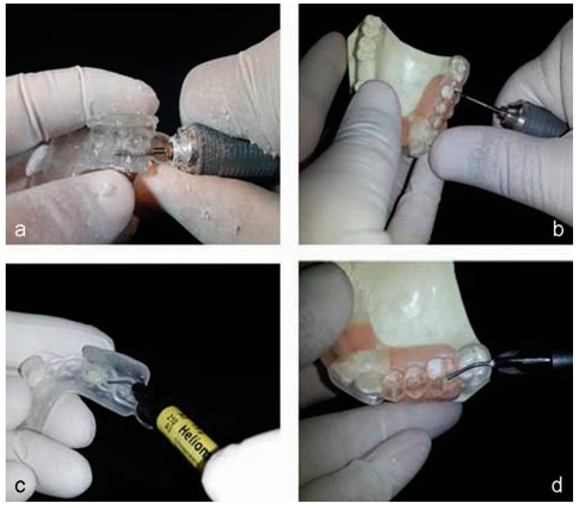
    • Preparation of reference markers on the radiographicstent: Using a fissure bur (HM 33 701; Meisinger Co., Hansemannstr, Neuss, Germany), a 1-mm deep groove was prepared in the middle of the mesiodistal width of the formed crowns at the most suitable location for the sagittal view of the 3D tomographic imaging. The groove was marked by applying flowable composite resin (Heliomolar Flow, Ivoclar Vivadent Co., Amherst, NY; Figure 2) and subsequent light curing (Aria Luxe Blue Pess; T. Apadana Co., Iran). Using a rotary bur (HM 487 GX; Meisinger Co., Germany) and strong series micromotor handpiece (Saeshin Precision Co., Daegu, Korea), a thin layer was removed from beneath the radiographic stent at the edentulous areas and after ensuring there was no contact between the acrylic and patient’s gingival mucosa, a layer of flowable composite was applied beneath the stent. Radiographic stent was placed in the patient’s mouth and the flowable composite was polymerized using UV light curing unit (Aria Luxe Blue Pess; T. Apadana Co., Iran) for 20 s.
  • Obtaining a CBCT scan along with the radiographic stent in place: A 3D tomogram was obtained with the radiographic stent in patient’s mouth. Using the composite marker in the groove prepared on crowns, an optimal tomographic section was chosen for the assessment of bone and softtissue structures. In the cross-sectional view, thecomposite laid beneath the radiographic stent indicates the outer surface of the soft tissue (Figure 3).
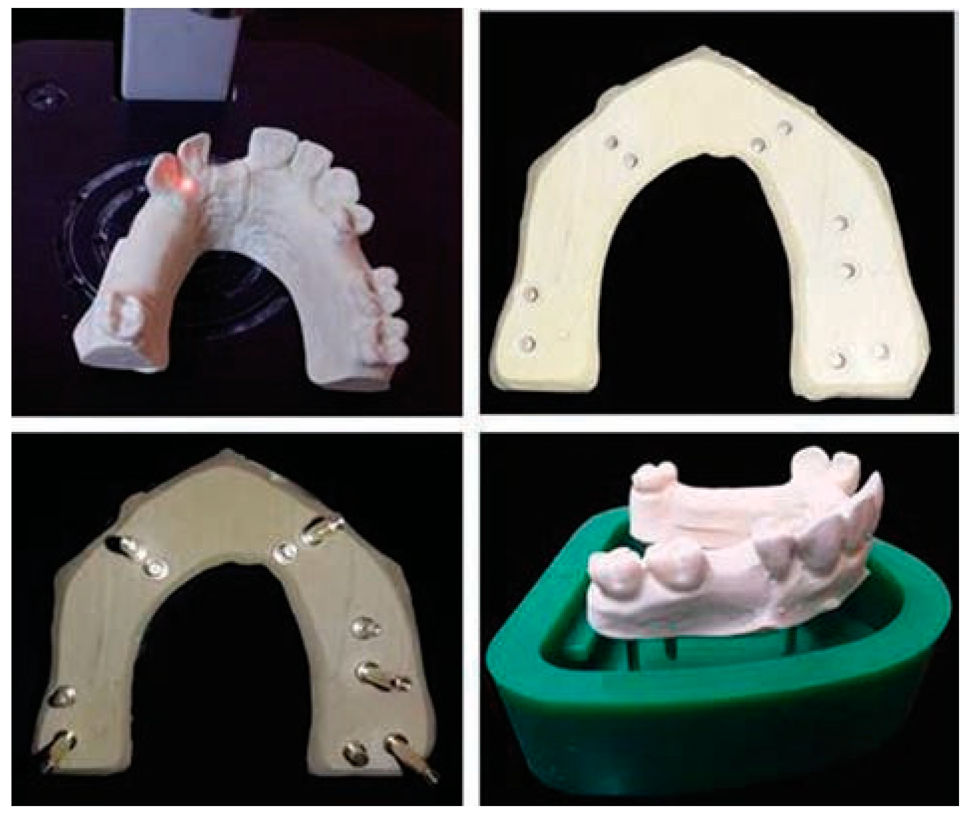
  • Fabrication of surgical stent: Another impression was made from patient’s mouth using additional silicon impression material (Monopren; Kettenbach Co., Germany) and poured with dental stone (type IV stone; GC Co., Belgium). After completion of the setting time, several parallel dowel pins were placed in the impression using the Pindex method to provide a master cast with individually removable dies at the site of hypothetical implants. The base was then poured with dental stone (Figure 4).
  • Determining the 3D implant position on the working cast:
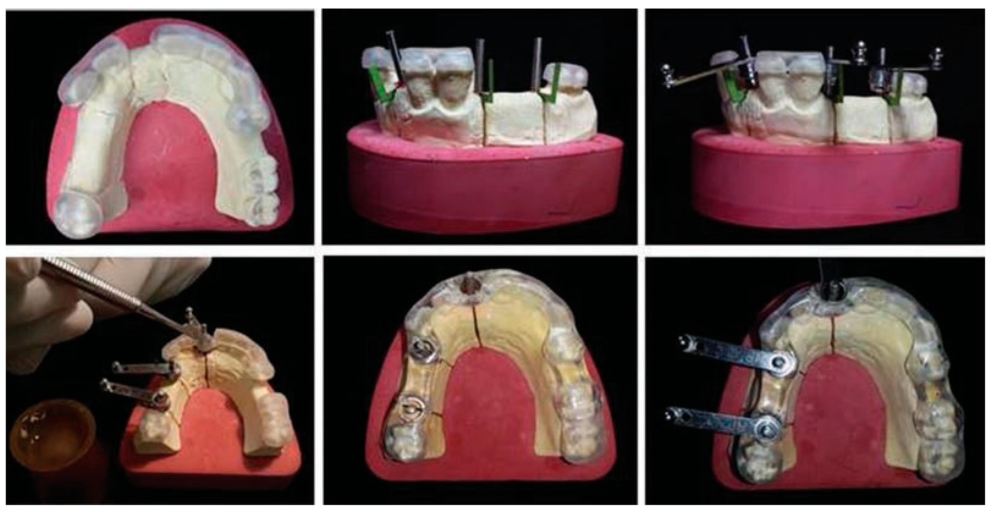
    • Determination of the center of implant placement: A round-end fissure bur (NO 882; Teeskavan Co., Iran) was inserted into the crown center along the longitudinal axis of the crown until reaching the cast surface. The tip of a pin was soaked with fit checker and inserted into the created path to mark the prosthetically optimal point for implant placement at the center of the final crown. Three sections were made at the center of the marked area to provide individually removable segments (Figure 5).
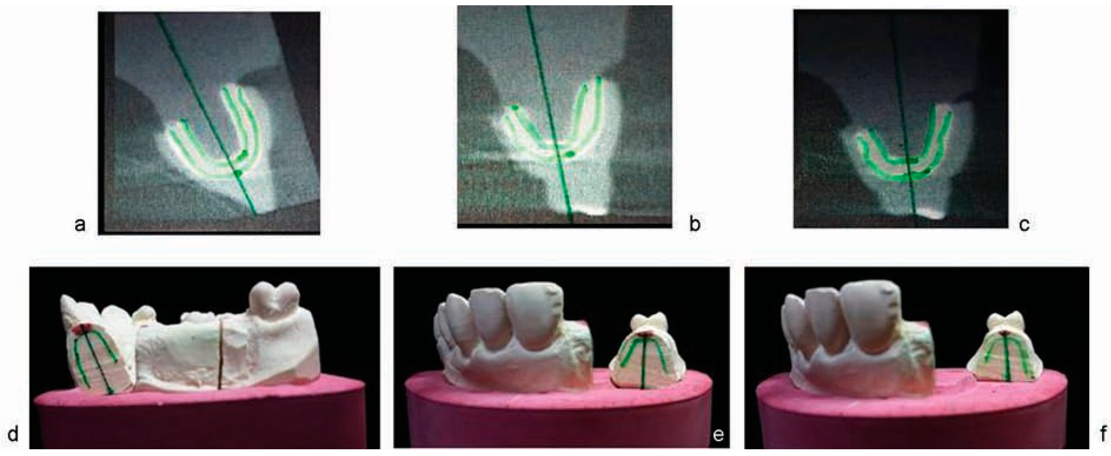
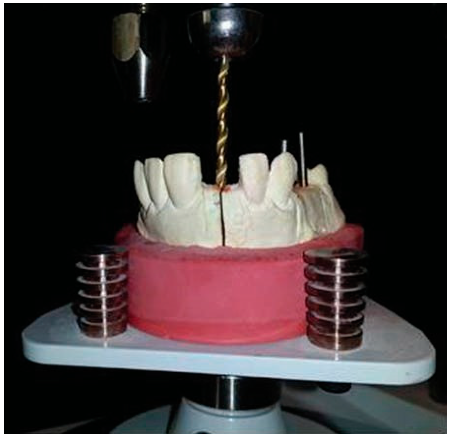
    • Determination of the bucco-palatal direction of implant insertion: A transparent sheet was superimposed on the tomogram of the implant site and fixed. The internal borders of the soft tissue and external borders of bone were outlined on the sheet. Using the lateral view of the crown and bone, the best bucco-palatal position for implant insertion was determined by drawing a line. The coronal point of the line corresponded to the predetermined central point (Figure 6). The transparent sheet was cut along the soft-tissue indicator line and the remaining piece was adapted to the sectioned cast. The bone indicator lines and the hypothetical long axis of the implant were also transferred to the cast. Considering the preset mesiodistal and buccolingual position of implant and the direction of its long axis, the osteotomy hole was simulated on the cast using a surveyor and milling machine (Saeshin Precision Co.). The hole measured 2 mm in diameter with a depth at the level of the cast base. To ensure optimal accuracy, the cast was transferred to a surveyor with an analyzer rod along the hypothetical line indicative of the long axis of implant. The surveyor was fixed in this position and the hole was prepared by the milling machine (Figure 7).
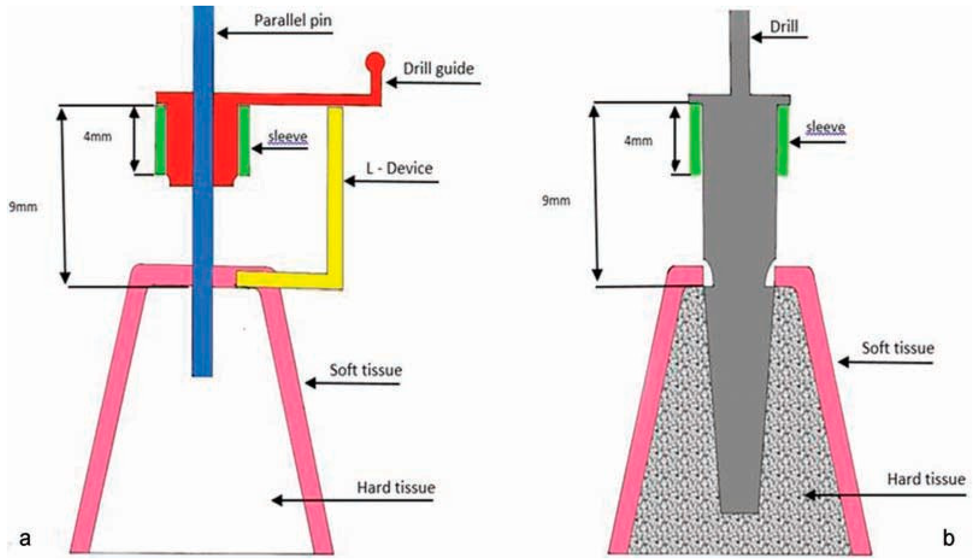
    • Determining the penetration depth of drill: The soft-tissue thickness, sleeve height, and the size of the possible gap between the sleeve and the underlying soft tissue were transferred to the surgical stent to precisely determine the penetration depth of drill and consequent depth of implant insertion. For this purpose, a horizontal line was drawn tangent to the crestal bone indicator line and perpendicular to the long axis of the implant path. An L-shaped guide was cut out of a plastic sheet in such way that the length of its long arm was 9 mm. The 9-mm length was selected because the drill stopper height was 9 mm in the implant system used (Noble Guide, Noble Biocare Co., Sweden). The short arm of the L-shaped guide was placed on bone crest tangent to the hypothetical horizontal line. The parallel pin was placed in the osteotomy hole parallel to the long arm of the L-shaped guide (Figure 8). The sleeve was fixed to the drill guide using wax. The complex of drill guide and sleeve was placed over the pin and the drill guide shank was fixed to the superior margin of the long arm of L-shaped guide. In other words, the drill guide and sleeve had 9 mm height similar to the length of the long arm of L-shaped guide. Thus, when the drill guide–sleeve was placed on the gingival tissue, the drill stopper corresponded to the coronal position of sleeve and pin guide and the actual height of drill would enter in the bone (Figure 9).
  • Fabrication of surgical stent: This was done with two different materials. We used heat-cure acrylic resin (Meliodent heat-curing polymer; Meliodent, Heraeus-Kulzer GmbH, Wehrheim, Germany) and pressure pot in areas other than the surgical site and clear cold-cure acrylic resin (cold-curing polymer; Meliodent, Heraeus-Kulzer GmbH, Wehrheim, Germany) at the site of implant placement. By merging these two components, the sleeve was fixed in the acrylic resin in such a way that the distance from the sleeve crest to the bone crest was 9 mm (Figure 10). The polished surgical stent was placed in the patient’s mouth and the drilling was completed using guided surgery drills specific for each implant system.
Figure 1. Steps to fabricating radiographic stent. (a) Lateral view of the waxed-up cast. (b) Occlusal view of the waxed-up cast. (c,d) Wax up of the teethed section and vestibule area. (e,f) Wax elimination and acrylic model fabrication.
Cmtr 10 00039 g001
Figure 2. Preparation of reference markers on the radiographic stent. (a) Making a space beneath the radiographic stent by cutting a thin layer. (b) Preparing a groove in the acrylic resin to determine the center of the desired crown. (c) Applying a layer of flowable composite beneath the stent. (d) Applying flowable composite into the prepared groove on occlusal surface.
Cmtr 10 00039 g002
Figure 3. 3D tomography along with the radiographic stent: soft-tissue layer and the exact location of the final crown are detectable due to radiopacity of the composite.
Cmtr 10 00039 g003
Figure 4. Providing a master cast with individually removable dies at the site of hypothetical implants using the Pindex method.
Cmtr 10 00039 g004
Figure 5. Marking the central spot for implant placement: (a) The pin—soaked with fit checker—is inserted into the created path, as far as it reaches the cast surface. (b) Marked spots on the cast. (c) Region was cut to removable segments at the center of the marked area.
Cmtr 10 00039 g005
Figure 6. Determination of the bucco-palatal direction of implant insertion: (ac) The desirable bucco-palatal position for implant insertion was determined for replacing the central incisor, first premolar, and first molar teeth. (df) The indicator lines were transferred to the cast.
Cmtr 10 00039 g006
Figure 7. The osteotomy hole was simulated on the cast using a surveyor and milling machine.
Cmtr 10 00039 g007

Results

In our pilot study, we used the described technique to place eight implants in three jaw models and eight implants for three patients.
The efficacy of iGIP for implant placement in the model: The cast used for the fabrication of iGIP belonged to a model that required replacement of the maxillary central incisor, first and second premolars, and first molar teeth. The treatment plan comprised dental implant placement at the site of maxillary central incisor, first premolar, and first molar teeth using flapless guided surgery (Figure 11).
The efficacy of iGIP for implant placement in patients: Figure 12 shows the iGIP fabrication steps on the cast, guided surgery and accuracy of implant insertion in its predetermined position in posterior, single implant cases. Figure 13 also shows the pre- and post-guided surgery images of single implant placement in the aesthetic zone.
Figure 8. Determining the penetration depth: (a) Measuring the length between the cutting end of the drill and its stopper. [Note that the 9-mm length was selected here because the drill stopper height was 9 mm in the implant system used]. (b) Determining the bone crest level for placement of the L-shaped guide. (c) Placement of the L-shaped guide. (d) The parallel pin was placed in the osteotomy hole parallel to the long arm of the L-shaped guide. (e) The sleeve was fixed to the drill guide using wax. (f) The complex of drill guide and sleeve was placed over the pin and the drill guide shank was fixed to the superior margin of the long arm of L-shaped guide.
Cmtr 10 00039 g008
Figure 9. The schematic view of the pin and the drill in the surgical guide. (a) The sleeve was fixed in a position in which there would be 9 mm distance from its coronal edge to the bone crest level. (b) Therefore, depth of the penetration in bone will be equal to the desired depth of osteotomy hole.
Cmtr 10 00039 g009

Discussion

Dental implants have entered a new era. In the past, osseointegration of dental implants was the only concern of clinicians; however, at present, despite advances in implantology and easier and faster placement of implants with less complication, clinicians are faced with new challenges due to the complexity of procedures and higher patient expectations. Guided surgery has been the focus of attention of researchers in the recent years due to its numerous advantages for dental implantation [9]. This technique eliminates the need for flap elevation in case of adequate available bone [5]. Flapless surgery is desired by both clinicians and patients due to less pain and discomfort during the initial healing phase [10]. The key point to enhance the precision of guided surgery is accurate transfer of the position of hypothetical implants on the 3D tomogram to the patient’s mouth [11].
As the interactive techniques such as the optical tracking system are not commonly used in dental clinics, fabrication of a surgical stent based on a tomogram with radiographic stent is necessary [12].
The previous methods of fabrication of surgical stent were mainly based on the tomographic data of available bone dimensions, and the thickness and anatomy of the soft tissue at the surgical site were not taken into account. Disregarding the soft-tissue thickness, particularly in areas where this thickness reaches 5 mm, can cause errors in the 3D position of implants placed via the flapless surgery.
Figure 10. Fabrication of surgical stent and fixing the sleeve.
Cmtr 10 00039 g010
Figure 11. Evaluating accuracy of implant placement in three sections of central incisor, first premolar, and first molar teeth on the model cast.
Cmtr 10 00039 g011
Figure 12. Accuracy of implant placement in its predetermined position in a posterior, single-implant case using a flapless method.
Cmtr 10 00039 g012
Figure 13. Surgical steps of a single-implant placement in the maxillary aesthetic zone: (a) Determining the favorable prosthetic region in an insertion site with sufficient bone to host a 3.7-in 10-mm implant. (b) Placement of the fixed surgical stent which has been fixed with adjacent teeth in the second patient. (c) Placement of the sleeve into the surgical stent. (d) Drilling using an initiative 2-mm drill.
Cmtr 10 00039 g013
Evidence shows that the mean accuracy of the position of implants placed with the conventional surgical stents is 1 mm and the deviation of their long axis is 5 degrees [13]. However, a meta-analysis on 19 reports demonstrated the possible deviation from the central point of entry of implant to be 6.5 mm, deviation from the implant apex position to be 6.9 mm, and deviation of the long angle of implant to be 24.9 degrees [8]. However, others have indicated that the maximum error at the central point of entry and apex of implants placed via the guided flapless surgery does not exceed 1.22 to 2 mm [1]. As mentioned earlier, one main reason for such significant differences may be disregarding the soft-tissue anatomy of the implant site. The higher the thickness of soft tissue and the less the adaptation of soft-tissue contour with the underlying bone, the greater the risk of inaccurate results due to the fabrication of a surgical stent based on the available bone observed on tomograms.
In this study, we presented a new iGIP, which is easily accessible for all clinicians. It is fabricated based on the soft- and hard-tissue data acquired from tomographic imaging of bone and determines the amount of available bone. Moreover, it specifies the outline of soft tissue covering the bone. The latter is particularly important in dimensional equations. Disregarding the soft tissue is one major problem of many previous navigation systems; because in these systems, the implant site and dimensions of the surgical model are determined based on the hard-tissue data and after placing the surgical model on the soft tissue (flapless technique) without considering reliable references, risk of errors increases in the three dimensions.
Advantages of iGIP are as follows:
  • Inclusion of the thickness and anatomy of the soft tissue in designing and manufacturing the surgical model
  • Simultaneous use of 3D data acquired from the tomogram and diagnostic cast
  • Determining the 3D position of bone based on the available bone on the 3D tomogram and position of the final crown (diagnostic cast wax up)
  • Introducing an affordable and easily accessible technique not requiring specific laboratory equipment
  • Compatibility with different implant systems
  • Applicability in both flap and flapless surgeries
  • Applicable for placement of one or several implants
  • High accuracy and safety
Limitations of iGIP are as follows:
  • Requiring tomographic imaging data
  • Time required for preparation of surgical model
  • Requiring sleeve and guided surgery drills specific for each implant system
  • Requiring intraoral references such as the adjacent teeth in partially edentulous patients or fixation of surgical model in fully edentulous cases
Obviously, further studies are required to determine the accuracy of iGIP prior to its extensive application for single-tooth and multiple-teeth replacements and full arch reconstruction. Similar to previous devices, fixation of iGIP in a fully edentulous ridge requires special fixation screws [14].

Conclusion

iGIP can be considered for use in dental clinics due to its easy application, affordability, and availability. This device can enhance the safety and efficacy of surgical stents for implant placement via the flapless technique without requiring specific equipment for making prosthetic-driven surgical stent. The main advantage of this device is that it takes into account both the soft-tissue and hard-tissue parameters to determine the optimal 3D position of implants. Future studies are warranted to confirm its higher efficacy in comparison with the conventional techniques.

References

  1. Schneider, D.; Marquardt, P.; Zwahlen, M.; Jung, R.E. A systematic review on the accuracy and the clinical outcome of computerguided template-based implant dentistry. Clin Oral Implants Res 2009, 20 (Suppl. S4), 73–86. [Google Scholar] [CrossRef] [PubMed]
  2. Akça, K.; Iplikçioğlu, H.; Cehreli, M.C. A surgical guide for accurate mesiodistal paralleling of implants in the posterior edentulous mandible. J Prosthet Dent 2002, 87, 233–235. [Google Scholar] [CrossRef] [PubMed]
  3. Tsuzuki, T.; Matsuura, T.; Kido, H.; Ishikawa, M.; Ukon, S.; Sato, H. New fabrication system for dental implant surgical stents: Time-saving laboratory technique using a light-curing resin and transparent artificial teeth. Clin Implant Dent Relat Res 2001, 3, 107–110. [Google Scholar] [CrossRef] [PubMed]
  4. Kang, S.H.; Lee, J.W.; Lim, S.H.; Kim, Y.H.; Kim, M.K. Verification of the usability of a navigation method in dental implant surgery: In vitro comparison with the stereolithographic surgical guide template method. J Craniomaxillofac Surg 2014, 42, 1530–1535. [Google Scholar] [CrossRef] [PubMed]
  5. de Almeida, E.O.; Pellizzer, E.P.; Goiatto, M.C.; et al. Computer-guided surgery in implantology: Review of basic concepts. J Craniofac Surg 2010, 21, 1917–1921. [Google Scholar] [CrossRef] [PubMed]
  6. Widmann, G.; Bale, R.J. Accuracy in computer-aided implant surgery—A review. Int J Oral Maxillofac Implants 2006, 21, 305–313. [Google Scholar] [PubMed]
  7. Whitehouse, J. Technology helps an “amateur” place implants. Dent Today 2008, 27, 120–124. [Google Scholar] [PubMed]
  8. Van Assche, N.; Vercruyssen, M.; Coucke, W.; Teughels, W.; Jacobs, R.; Quirynen, M. Accuracy of computer-aided implant placement. Clin Oral Implants Res 2012, 23 (Suppl. S6), 112–123. [Google Scholar] [CrossRef] [PubMed]
  9. Sicilia, A.; Botticelli, D.; Working Group 3. Computer-guided implant therapy and soft- and hard-tissue aspects. The Third EAO Consensus Conference 2012. Clin Oral Implants Res 2012, 23 (Suppl. S6), 157–161. [Google Scholar] [CrossRef] [PubMed]
  10. Hultin, M.; Svensson, K.G.; Trulsson, M. Clinical advantages of computer-guided implant placement: A systematic review. Clin Oral Implants Res 2012, 23 (Suppl. S6), 124–135. [Google Scholar] [CrossRef] [PubMed]
  11. Azari, A.; Nikzad, S. Flapless implant surgery: Review of the literature and report of 2 cases with computer-guided surgical approach. J Oral Maxillofac Surg 2008, 66, 1015–1021. [Google Scholar] [CrossRef] [PubMed]
  12. Neugebauer, J.; Stachulla, G.; Ritter, L.; et al. Computer-aided manufacturing technologies for guided implant placement. Expert Rev Med Devices 2010, 7, 113–129. [Google Scholar] [CrossRef] [PubMed]
  13. Nickenig, H.J.; Eitner, S.; Rothamel, D.; Wichmann, M.; Zöller, J.E. Possibilities and limitations of implant placement by virtual planning data and surgical guide templates. Int J Comput Dent 2012, 15, 9–21. [Google Scholar] [PubMed]
  14. Elsyad, M.A. A new surgical template with a handpiece positioner for use during flapless placement of four dental implants to retain a mandibular overdenture. J Prosthodont 2012, 21, 573–577. [Google Scholar] [CrossRef]