Article

Design Evaluation of FFF-Printed Transtibial Prosthetic Sockets Using Follow-Up and Finite Element Analysis

1
3D Lab Radboudumc, Radboud University Medical Center, 6525 GA Nijmegen, The Netherlands
2
Mechanical Engineering, University of Twente, 7522 NB Enschede, The Netherlands
3
Orthopedic Research Lab, Radboud University Medical Center, 6525 GA Nijmegen, The Netherlands
*
Author to whom correspondence should be addressed.
Prosthesis 2022, 4(4), 589-599; https://doi.org/10.3390/prosthesis4040048
Submission received: 12 September 2022 / Revised: 7 October 2022 / Accepted: 11 October 2022 / Published: 14 October 2022
(This article belongs to the Special Issue 3D Printing Strategies for Limb Prostheses)

Abstract

:
Background: Participants in Sierra Leone received a Fused Filament Fabrication (FFF)-printed transtibial prosthetic socket. Follow-up was conducted on this group over a period of 21 months. To investigate the failure of some of the FFF-printed transtibial sockets, further strength investigation is desired. Methods: A finite element (FE) analysis provided an extensive overview of the strength of the socket. Using follow-up data and FE analyses, weak spots were identified, and the required optimization/reinforcement of the socket wall was determined. Results: Five sockets with a 4 mm wall thickness were tested by five participants. The strength of the 4 mm prosthetic socket seemed to be sufficient for people with limited activity. The 4 mm sockets used by active participants failed at the patella tendon or popliteal area. One socket with a wall thickness of 6 mm was used by an active user and remained intact after one year of use. An FE analysis of the socket showed high stresses in the patella tendon area. An increased wall thickness of 7 mm leads to a decrease of 26% in the stress corresponding to the observed failure in the patella tendon area, compared to the 4 mm socket. Conclusions: Follow-up in combination with an FE analysis can provide insight into the strength of the transtibial socket. In future designs, both the patella tendon and popliteal area will be reinforced by a thickened trim line of 7 mm. A design with a thickened trimline of 7 mm is expected to be sufficiently strong for active users. Another follow-up study will be performed to confirm this.

1. Introduction

There is a limited availability of prostheses in low- and middle-income countries. The WHO estimates that only one in ten people in need of prostheses have access to them. This is due to a lack of materials, trained personnel, high cost, and a lack of information concerning the availability of prostheses [1]. Three-dimensional printing can provide a relatively simple but useful solution for manufacturing locally produced prostheses using a standardized digital workflow. Staff could be locally trained to complete the prosthetic fitting, and through standardization, the process would become less dependent on the individual’s skill and experience.
In collaboration with the 3D lab at the Radboud University Medical Center in the Netherlands, we set up a 3D lab at Masanga Hospital in Sierra Leone. Here, the local population has been trained to produce low-cost 3D-printed prostheses. The 3D printing technique used at Masanga Hospital was Fused Filament Fabrication (FFF). Compared with other 3D printing techniques, FFF is a more readily available 3D printing method with lower associated costs. Using FFF in combination with a standardized workflow, transtibial prosthetic sockets were produced for people with lower-limb amputations.
The initial design of the socket was based on previous research, in which experimental testing on FFF materials and the socket design were performed [2]. Based on the test results of the 3D-printed materials, tough polylactic acid (PLA) was selected as the optimal material for the prosthetic socket. This was due to its high layer-on-layer binding, ease of use during printing (good adhesion and minimal warpage), and low costs. Subsequently, a 3D-printed transtibial prosthetic socket was tested according to the ISO standard for structural testing of lower-limb prostheses (ISO 10328) [3]. The socket successfully endured a maximum load of 6700 N without fracture and completed 2.27 million steps during the cyclic test with a maximum compressive force of 1200 N [2]. Failure during the dynamic test, which required three million steps before failure, occurred at the connection of the socket to the metal prosthetic adaptors. However, based on these results, it was concluded that the 3D-printed prosthetic sockets were sufficiently durable to test in practical life. Therefore, in 2020, eight participants in Sierra Leone were given a transtibial prosthesis and have been followed for the past two years.
FFF-printed sockets are rarely produced, and little research has been published on the strength and long-term follow-ups of these devices [4,5,6,7]. Like our previous mechanical tests, other studies also use ISO 10328 as a guideline for the mechanical testing of prosthetic sockets [4,5,7,8,9,10]. Although ISO 10328 is a standard for testing prosthetic components, it is not a standard to test prosthetic sockets. While the ISO 10328 test is useful to demonstrate the structural integrity of sockets, it has some limitations related to how the prosthesis is used and loaded in real life. In the test setup, the distal part of the socket was lined with a thin layer of foam and filled with bone cement, which was connected to the loaded applicator. This meant that, when loaded, stresses were mainly applied to the distal part of the socket, thereby bypassing the proximal part of the socket, which remained untested. In addition, the relatively stiff filling distributed the pressure across the inner surface of the socket wall, while the actual pressures are known to vary due to the internal soft and hard tissue structures of the stump and due to the specific socket design [11]. Therefore, additional research is necessary to verify the structural integrity of the socket wall during actual use to further improve the 3D-printed design.
The finite element (FE) method is a useful tool to evaluate the structural integrity of prosthetic sockets. Its applicability to transtibial sockets has been shown in computational studies that used FE to evaluate the structural strength of new socket designs and to determine optimal design parameters [12,13,14,15,16,17,18,19,20]. In the current study, we developed an FE model of our socket design to determine the structural behaviour of the socket wall. We aimed to obtain a realistic load transfer from the stump to the socket to overcome the limitations of load by-pass observed in the regular ISO testing standard.
In this paper, we present the results of the long-term follow-ups of the first eight 3D-printed transtibial prosthetic sockets. These results were combined with the results of the FE simulations of the socket to provide an in-depth overview of the strength of the socket during activities of daily life. Based on the combined results, we aimed to identify weak spots in the socket design. By reinforcing these critical locations in the socket, the socket design can be improved.

2. Materials and Methods

2.1. Part I: Follow-Up Study

During a period of two months, from February until March 2020, eight participants received a 3D-printed transtibial prosthesis in the Masanga Hospital in Sierra Leone [21].
The protocol of this study was reviewed and approved by the Scientific Research Committee of the Masanga Medical Research Unit (MMRU). On the 6th of January 2019, ethical approval was obtained from the Sierra Leone Ethics and Scientific Review Committee. Written informed consent was obtained from all participants included in this study.
To test the use of the prostheses, all participants were interviewed using purpose-developed questionnaires. The interviews were conducted before obtaining the prostheses, after five to six weeks of follow-up, and after a follow-up period of 21 months. Due to the evolving COVID-19 pandemic, the project had to be temporarily put on hold. This made it difficult to have regular follow-up moments and to provide guidance to the staff at Masanga Hospital. However, two local physiotherapists stayed in close contact with all participants. Regular visits were possible as both physiotherapists lived in the same village as the participants. Participants were monitored during this period without questionnaires. The information gained from these visits was forwarded to the research team in the Netherlands.

Prosthetic Socket Production

The patient-specific transtibial sockets were based on the 3D geometry of the stump. The dimensions of the stump were scanned with a texture handheld 3D scanner (Einscanner Pro Plus, Shining 3D-Technology, Hangzhou, China). A custom-made transtibial socket with a 4 mm wall thickness was designed in a free-to-use 3D software tool (Autodesk Meshmixer 3.5, Toronto, ON, Canada). Sockets were 3D printed with an Ultimaker S5 (Ultimaker BV, Geldermalsen, Netherlands), located at Masanga Hospital, out of tough PLA (Ultimaker BV, Geldermalsen, Netherlands). The socket was printed with a 0.8 mm print core, 100% circular infill, 0.2 mm layer thickness, and a print speed of 45 mm/s [22]. The prosthetic socket was connected to the adaptor with four M6 locknuts (Galvanised, DIN 985) [2].
Some of the prosthetic sockets failed during the follow-up. These participants received a new socket with an improved design, in which the wall thickness was increased from 4 to 6 mm. In addition, the shape of the bottom of the socket was changed from square to circular to avoid stress concentrations at the corners.

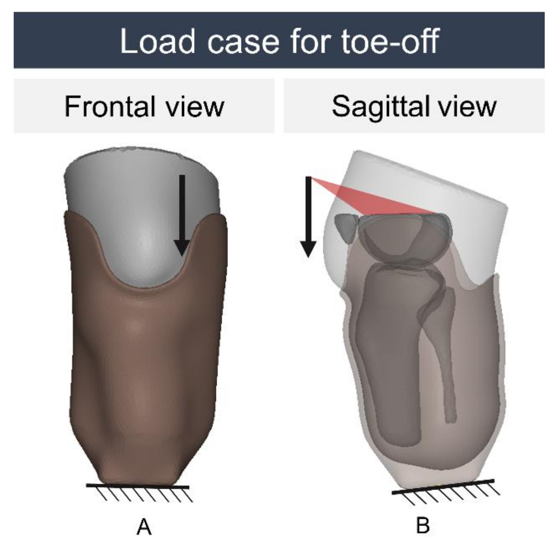
2.2. Part II: Finite Element Model

To determine the stress distribution inside the 3D-printed socket, an FE model was developed for a right-sided transtibial amputated leg with a tibial length of 16 cm. The FE model consisted of the socket and a residual stump including the soft tissues and a tibia, fibula, and distal parts of the femur and patella. The stump was modelled as one body with different mechanical properties and was connected to the socket through a glued contact. The material properties of the FFF-printed tough PLA were based on the results of tensile tests performed during earlier research, which showed a stiffness of 1.317 GPa, a tensile strength of 47.2 MPa in the longitudinal print direction, and a tensile strength of 27.9 MPa in the transversal print direction [2]. The Poisson’s ratio [23] and the material properties of the soft tissues and bones were based on the literature (Table 1) [19,24,25].
An automatic meshing tool was used to generate the FE mesh with tetrahedron elements with the desired edge length of 3 mm [26]. At the proximal part of the socket, the mesh was refined with an edge length of 1 mm to have a limited loss of geometry. The mesh was further improved to ensure each element had sufficient volume at the start of the simulation.
To investigate the stresses present in the socket during gait, the load cases during the most critical phases of the gait cycle (heel strike and toe-off) were applied according to ISO 10328. This equalled a compressive load of 3360 and 3019 N for heel strike and toe-off, respectively [3]. To correctly transfer this load to the socket, the model was translated, rotated, and tilted to match the configurations defined in ISO 10328 with a distance of 158 mm between the socket bottom and the intercondylar notch of the tibia. The correct configuration was described by the translations in Table 2. After achieving the correct position and orientation, the bottom of the socket was fully constrained. Next, the load was defined as a point load applied to the top surface of the femur. A schematic overview of the load case for toe-off is shown in Figure 1. The simulations were performed using MSC.Marc Mentat (MSC Software, version 2021.1, Irvine, CA, USA).
To study the effect of the wall thickness on the magnitude of the stresses present in the socket, four versions of the socket were evaluated. One socket was given a wall thickness of 4 mm to match the socket design of the clinical trial. The other sockets were given wall thicknesses of 5, 6, and 7 mm. Wall thicknesses larger than 7 mm would result in the socket being too bulky and heavy and were therefore not included in the study.

3. Results

3.1. Part I: Follow-Up Study

Eight transtibial sockets were made from February to March 2020. One participant died after two weeks of rehabilitation due to a heart attack, considered unrelated to the study. Another participant died after three months due to sickle cell disease. A third participant moved and was no longer traceable. An overview of the characteristics of the five remaining participants, including the estimated use of the prosthesis, is presented in Table 3.
During a short-term follow-up of five to six weeks, all participants were still wearing the prosthesis.
After 21 months, the socket of participant 001 was still completely damage-free. The participant reported wearing the prosthesis seven days a week throughout the whole day. The main activities of the participant were walking indoors and short distances outside the house for approximately 15 min in one day.
Participant 002 indicated that the prosthetic socket failed after an estimated time of three months. The socket was broken at the lateral side of the popliteal (Figure 2, Left). Unfortunately, the physiotherapists did not notice this. Therefore, this participant did not receive a new socket. The participant indicated that he still occasionally used the prosthesis for aesthetic purposes.
Participant 003 stopped wearing the 3D-printed prosthesis after approximately six weeks because of a blister developing on the tibia end. The participant started using an old prosthesis again. The 3D-printed socket was intact at the long-term follow-up.
At an estimated time of 6 to 7 weeks after receiving the prosthesis, the sockets of participants 004 and 005 fractured in the patella region (Figure 2, Right). New sockets with an increased wall thickness of 6 mm were 3D printed for these participants in November 2020. After a long-term follow-up of one year, participant 004 was still extensively using the 6 mm socket. The participant indicated wearing the prosthesis seven days a week, approximately three hours a day. This corresponded to an actual walking time of 30 min to 1 h per day. The prosthesis looked worn but was structurally still intact after one year.
Unfortunately, participant 005 never used the new socket. The old cover was re-used but broken due to the size mismatch with the new and wider socket. Both the participant and physiotherapists assumed that this meant the prosthesis could no longer be used. This was very unfortunate since the cover only serves an aesthetic purpose and does not add to the structural strength of the prosthesis.

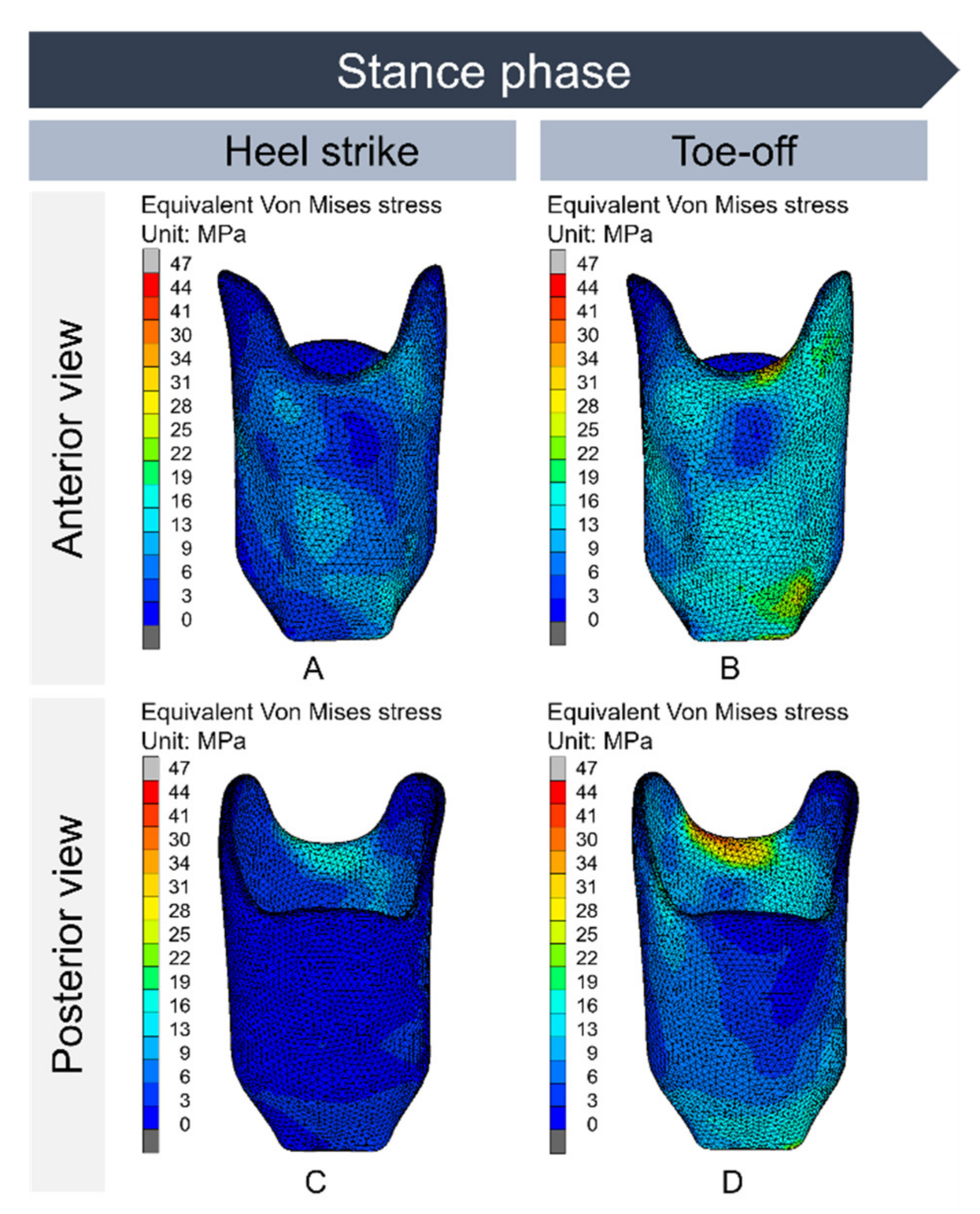
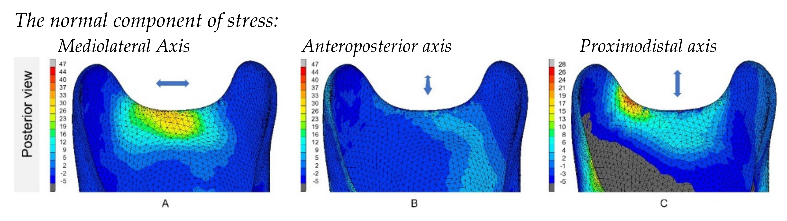
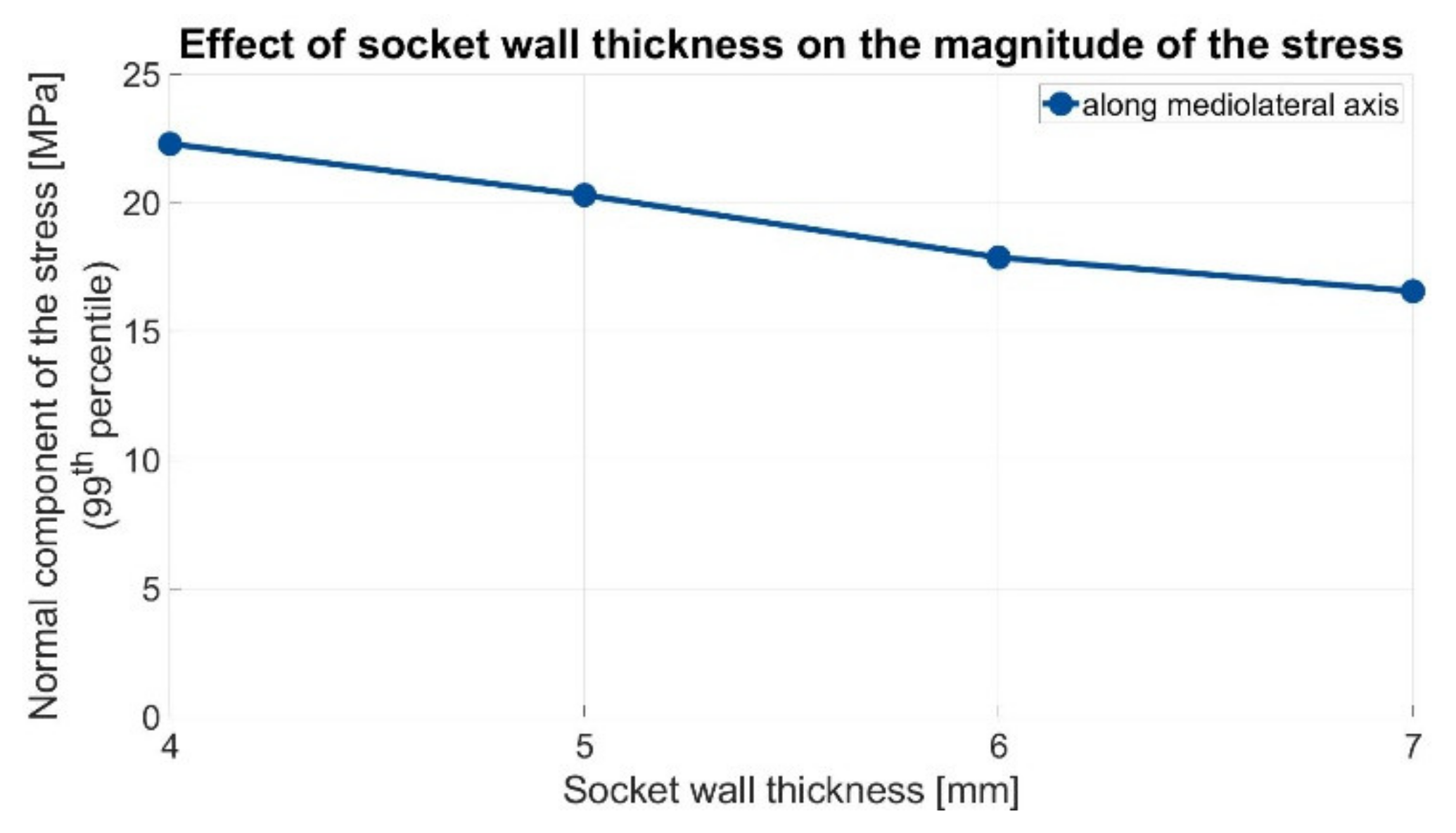
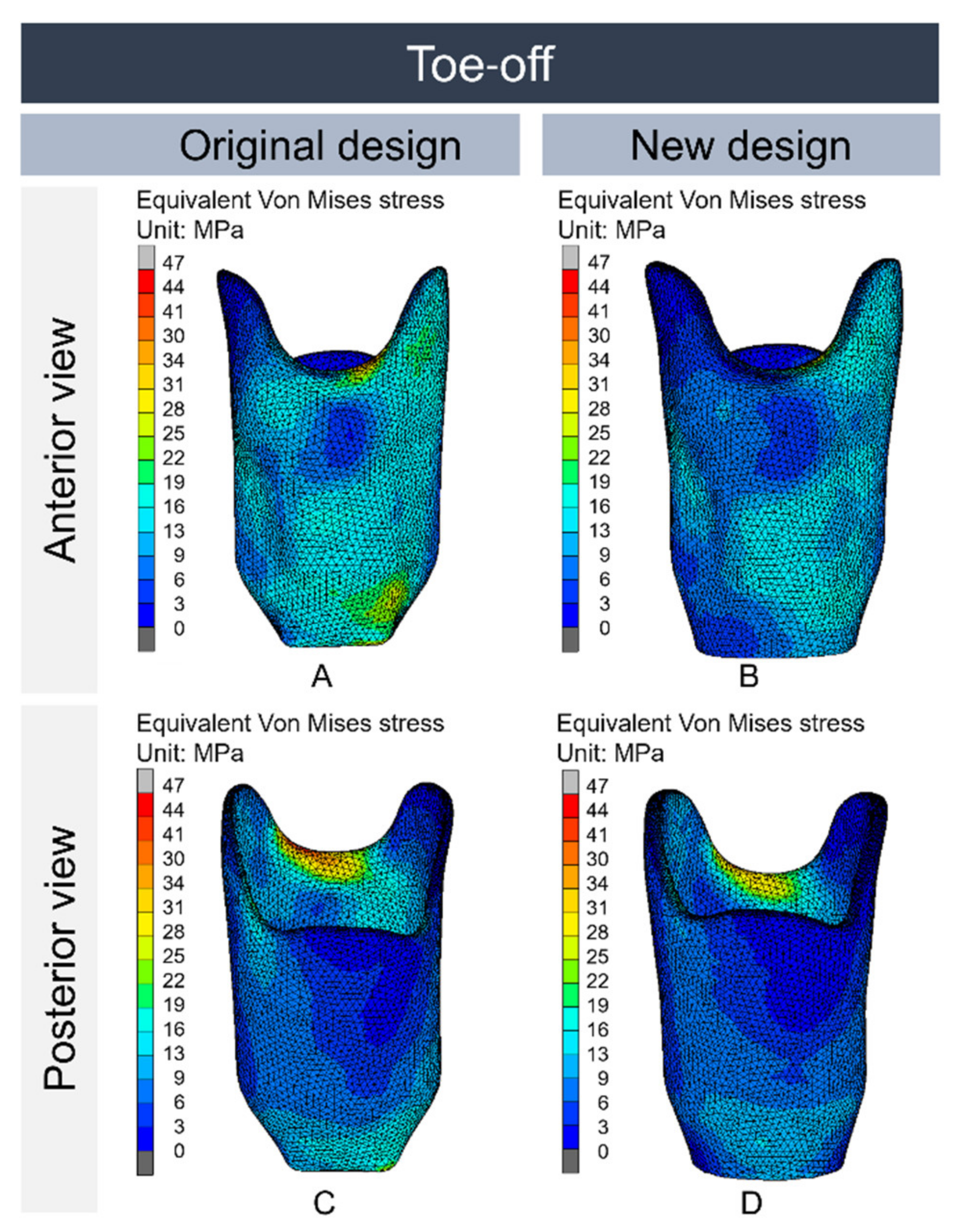
3.2. Part II: Finite Element Model

The FE analysis showed the highest stresses during toe-off in the region below the patella tendon (Figure 3). Considering the difference in material strength in the longitudinal and transversal printing directions, the tensile stresses were also calculated in these directions (Figure 4). The maximum value (red) in each of these figures corresponds to the failure stress in the given direction. The stresses in the socket with 4 mm thickness were close to the failure stress in the mediolateral and proximodistal directions. The high tensile stresses along the mediolateral axis corresponded with the tear observed in patient 004 during follow-up (Figure 2, Right).
To determine the actual effect of the wall thickness on the magnitude of these stresses, sockets with different wall thicknesses were simulated. By increasing the wall thickness of the socket, a general decrease in stress was observed. Observing the 99th percentile of the normal stresses in the mediolateral direction, decreases of 8.9%, 20%, and 26% were seen with wall thicknesses of 5, 6, and 7 mm, respectively (Figure 5).

4. Discussion

In this study, clinical results at one year and nine months of follow-up of low-cost 3D-printed transtibial prosthetic sockets were collected for five participants in a rural area of Sierra Leone. Follow-up showed that the strength of a 4 mm prosthetic socket seemed to be sufficient for people who had limited activity (small walks outside, but mainly limited to doing their household chores). A 6 mm prosthetic socket seemed to be more suitable for active users; one participant used this socket for over a year with the socket remaining intact. This participant was an active prosthetic user and was able to handle most barriers and do (paid) work.
FE simulations were used to gain more insight into the failure of prosthetic sockets observed during follow-up. Follow-up revealed that the patella and popliteal regions were weak areas in the prosthetic socket with a 4 mm wall thickness. The simulation results showed high stresses in the patella region, while only a slight increase in stress was medially seen in the popliteal area. Increasing the wall thickness led to a reduction of the peak stresses, confirming that a 6 mm thickness would be more suitable for practical use.
Unfortunately, there is very little recent literature available about the mechanical strength of FFF-printed prosthetic sockets, which makes a comparison of our results difficult. Two recent studies have been published [7,9], but these fail to provide crucial information about the printing technique that was used, longer-term follow-up, and information about the different designs that were tested. In addition, information on specific locations of failure of the prosthetic sockets is not always available. The study of Nickel et al. [9] investigated different percentages for infill patterns in the design of FFF-printed sockets. However, in the current study, we only tested prosthetic sockets with 100% infill to make the layer-on-layer connection as strong as possible. Interestingly, similar to our study, the study of Nickel et al. also reported socket breaks at the popliteal area.
Several studies have used finite element models to evaluate the structural strength of transtibial sockets [11,12,13,14,15,16]. However, the load cases used in these studies differ greatly. Some studies included only a vertical load in their structural analyses equal to (half) the body weight or to measured vertical ground reaction forces [14,16]. During walking, the loads acting on a socket also induce moments (bending and twisting). Therefore, other studies have measured the interface pressure or both forces and moments during the complete gait cycle and applied those to their model [12,17]. However, these studies did not seem to consider that a socket should withstand these loads more than once. To clarify, ISO 10328 prescribes a dynamic test force that is higher than the full body weight, in which the socket needs to be able to withstand three million cycles. Two studies did consider applying higher loads and used the ultimate static test force of ISO 10328; however, these studies applied the load to the socket through a rigid stump [18] or a connector plate [15]. This differed from reality, where the load is transferred to the socket through the softer stump.
In the current study, we attempted to create a model which reflected reality as closely as possible. A stump was modelled by creating a volume using a print of the inside of the socket. To realistically transfer the applied load from the stump to the socket, bone models were generated based on existing CT scans. Load cases were based on ISO 10328. The socket was tilted and rotated to represent the configuration for heel strike or toe-off. Finally, relatively high downward forces of 3360 N for heel strike and 3019 N for toe-off were applied.
In this study, only a single loading configuration was simulated (gait), which may not have been the activity that led to the fractures in the popliteal area. Additional simulations with alternative loading configurations could be useful to gain more insight into other failure mechanisms and locations and make the computational analyses more robust. It would therefore be desirable if a more appropriate guideline would become available for mechanical testing of transtibial prosthetic sockets [8]. It should also be noted that a socket is patient-specific, with each socket having a slightly different geometry, which has implications for the structural strength and stress distribution in the socket. In addition, socket stress and deformation appear to increase with the increasing length of the stump [17]. To avoid underestimation of the stress values, an FE model of a socket for a longer stump (tibia length of 16 cm) was devised.
The FE model consisted of a socket and a residual stump including the soft tissues and bones. While normally, sliding between the socket and stump is possible, the socket and the stump could not be separated during the simulation. This greatly simplified the model. However, during the simulation, the soft tissue of the stump was pushed over the anterior side of the socket. The prevention of the stump sliding along the socket introduced additional forces. This may explain why high tensile stresses were observed in the proximodistal direction (Figure 4C), while these were not observed during the follow-up. As the high tensile stresses along the mediolateral axis corresponded with the tear observed during the follow-up, the comparison between the sockets was based on this component of the stress.
Suggestions can be made for a new design iteration. Based on the follow-up and FE analyses, the patella tendon area was shown to be a weak area in the socket design. Furthermore, follow-ups showed a failure in the popliteal area. Therefore, in future designs, a wall thickness of 4 mm should be used for the distal part of the socket. Additionally, the wall thickness at the trimline should be increased to 7 mm, with a width of 3 cm and a gradient of 5 cm. As the weight and printing time significantly increased with a thicker socket wall, it was decided to reinforce only the trimline with 7 mm thickness. A 4-mm thick socket weighs 279 g (9 h and 29 min printing time) and a 7-mm thick socket weighs 451 g (15 h and 12 min printing time). A socket with only a thickened trimline is a good compromise between the two and weighs 378 g (12 h and 56 min printing time). In addition to the changes in the socket wall thickness, sharp curves at the trim line of the socket were removed to decrease stress concentrations at the corners of the popliteal depression. Moreover, as demonstrated in the second design that was used during follow-up, a round shape of the bottom of the socket could be used instead of a square one to reduce stress concentrations in that area. Preliminary simulations with these design changes showed lower peak stresses and more evenly distributed stresses throughout the socket (Figure 6).

5. Conclusions

The results of a long-term follow-up of five participants with a 3D-printed transtibial prosthetic socket showed that the current socket was sufficiently strong for users with low activity. Based on the follow-ups and FE simulations, design changes were proposed that led to a reduction in peak stresses in the critical areas (patella tendon area and popliteal area). Follow-up studies of a new cohort using 3D-printed prosthetic sockets with the new design will substantiate whether the theoretical rationale reflects practice.

Author Contributions

Conceptualization, M.v.d.S. and F.S.; data curation, M.v.d.S. and F.S.; investigation, M.v.d.S. and F.S.; methodology, M.v.d.S., F.S., T.B. and D.J.; project administration, M.v.d.S.; supervision, T.B., T.J.J.M. and D.J.; writing—original draft, M.v.d.S. and F.S.; writing—review and editing, M.v.d.S., F.S., T.B., T.J.J.M. and D.J. All authors have read and agreed to the published version of the manuscript.

Funding

This research received no external funding.

Institutional Review Board Statement

The protocol was reviewed and approved by the Scientific Research Committee of the Masanga Medical Research Unit (MMRU). On 6 January 2019, ethical approval for this study was obtained from the Sierra Leone Ethics and Scientific Review Committee.

Informed Consent Statement

Informed consent was obtained from all subjects involved in the study.

Data Availability Statement

Not applicable.

Conflicts of Interest

The authors declare no conflict of interest.

References

  1. World Health Organization. WHO Standards for Prosthetics and Orthotics; World Health Organization: Geneva, Switzerland, 2017. [Google Scholar]
  2. Van der Stelt, M.; Verhamme, L.; Slump, C.H.; Brouwers, L.; Maal, T.J.J. Strength testing of low-cost 3D-printed transtibial prosthetic socket. Proc. Inst. Mech. Eng. Part H J. Eng. Med. 2022, 236, 367–375. [Google Scholar] [CrossRef] [PubMed]
  3. NEN-EN-ISO 10328; Prosthetics—Structural Testing of Lower-Limb Prostheses—Requirements and Test Methods. European Committee for Standardization: Toronto, ON, Canada, 2016.
  4. Campbell, L.; Lau, A.; Pousett, B.; Janzen, E.; Raschke, S.U. How infill percentage affects the ultimate strength of 3D-printed transtibial sockets during initial contact. Can. Prosthet. Orthot. J. 2018, 1, 2. [Google Scholar] [CrossRef] [Green Version]
  5. Goh, J.C.H.; Lee, P.V.S.; Ng, P. Structural integrity of polypropylene prosthetic sockets manufactured using the polymer deposition technique. Proc. Inst. Mech. Eng. Part H J. Eng. Med. 2002, 216, 359–368. [Google Scholar] [CrossRef] [PubMed]
  6. Hsu, L.H.; Huang, G.F.; Lu, C.W.; Lai, C.W.; Chen, Y.M.; Yu, I.C. The Application of Rapid Prototyping for the Design and Manufacturing of Transtibial Prosthetic Socket. Mater. Sci. Forum 2008, 594, 273–280. [Google Scholar] [CrossRef]
  7. Stenvall, E.; Flodberg, G.; Pettersson, H.; Hellberg, K.; Hermansson, L.; Wallin, M.; Yang, L. Additive Manufacturing of Prostheses Using Forest-Based Composites. Bioengineering 2020, 7, 103. [Google Scholar] [CrossRef] [PubMed]
  8. Gariboldi, F.; Pasquarelli, D.; Cutti, A.G. Structural testing of lower-limb prosthetic sockets: A systematic review. Med. Eng. Phys. 2021, 99, 103742. [Google Scholar] [CrossRef] [PubMed]
  9. Nickel, E.A.; Barrons, K.J.; Owen, M.K.; Hand, B.D.; Hansen, A.H.; Desjardins, J.D. Strength Testing of Definitive Transtibial Prosthetic Sockets Made Using 3D-Printing Technology. JPO J. Prosthet. Orthot. 2020, 32, 295–300. [Google Scholar] [CrossRef]
  10. Faustini, M.C.; Neptune, R.R.; Crawford, R.H.; Rogers, W.E.; Bosker, G. An Experimental and Theoretical Framework for Manufacturing Prosthetic Sockets for Transtibial Amputees. IEEE Trans. Neural Syst. Rehabil. Eng. 2006, 14, 304–310. [Google Scholar] [CrossRef] [PubMed]
  11. Zhang, M.; Turner-Smith, A.R.; Tanner, A.; Roberts, V.C. Clinical investigation of the pressure and shear stress on the trans-tibial stump with a prosthesis. Med. Eng. Phys. 1998, 20, 188–198. [Google Scholar] [CrossRef]
  12. Faustini, M.C.; Neptune, R.R.; Crawford, R.H. The quasi-static response of compliant prosthetic sockets for transtibial amputees using finite element methods. Med. Eng. Phys. 2006, 28, 114–121. [Google Scholar] [CrossRef] [PubMed]
  13. Lee, W.C.C.; Zhang, M.; Boone, D.A.; Contoyannis, B. Finite-element analysis to determine effect of monolimb flexibility on structural strength and interaction between residual limb and prosthetic socket. J. Rehabil. Res. Dev. 2004, 41, 775–786. [Google Scholar] [CrossRef] [Green Version]
  14. Lenka, P.K.; Choudhury, A.R. Analysis of trans tibial prosthetic socket materials using finite element method. J. Biomed. Sci. Eng. 2011, 04, 762–768. [Google Scholar] [CrossRef] [Green Version]
  15. Lindberg, A.; Alfthan, J.; Pettersson, H.; Flodberg, G.; Yang, L. Mechanical performance of polymer powder bed fused objects—FEM simulation and verification. Addit. Manuf. 2018, 24, 577–586. [Google Scholar] [CrossRef]
  16. Mubarak, A.J.M.; Rashid, A.M.A.; Wahab, A.A.; Seng, G.H.; Ramlee, M.H. Customized Designs and Biomechanical Analysis of Transtibial Prosthetic Leg. J. Physics Conf. Ser. 2021, 2071, 012014. [Google Scholar] [CrossRef]
  17. Jweeg, M.J.; Hammoudi, Z.S.; Alwan, B.A. Optimised Analysis, Design, and Fabrication of Trans-Tibial Prosthetic Sockets. IOP Conf. Ser. Mater. Sci. Eng. 2018, 433, 012058. [Google Scholar] [CrossRef]
  18. Lee, W.C.C.; Zhang, M. Design of monolimb using finite element modelling and statistics-based Taguchi method. Clin. Biomech. 2005, 20, 759–766. [Google Scholar] [CrossRef] [PubMed] [Green Version]
  19. Zachariah, S.G.; Sanders, J.E. Finite element estimates of interface stress in the trans-tibial prosthesis using gap elements are different from those using automated contact. J. Biomech. 2000, 33, 895–899. [Google Scholar] [CrossRef]
  20. Ali, I.; Kumar, R.; Singh, Y. Finite element modelling and analysis of trans-tibial prosthetic socket. Glob. J. Res. Eng. 2014, 14, 43–50. [Google Scholar]
  21. Van der Stelt, M.; Grobusch, M.P.; Koroma, A.R.; Papenburg, M.; Kebbie, I.; Slump, C.H.; Maal, T.J.; Brouwers, L. Pioneering low-cost 3D-printed transtibial prosthetics to serve a rural population in Sierra Leone—An observational cohort study. EClinicalMedicine 2021, 35, 100874. [Google Scholar] [CrossRef] [PubMed]
  22. Van der Stelt, M.; Verhulst, A.; Slump, C.H.; Papenburg, M.; Grobusch, M.P.; Brouwers, L.; Maal, T.J. Design and Production of Low-Cost 3D-Printed Transtibial Prosthetic Sockets. JPO J. Prosthet. Orthot. 2021, Publish Ah, 1–7. [Google Scholar] [CrossRef]
  23. Thiago, R.; Ferreira, I.T.L.; Amatte, I.C.; Dutra, A.; Bürger, D. Experimental characterization and micrography of 3D printed PLA and PLA reinforced with short carbon fibers. Compos. Part B Eng. 2017, 124, 88–100. [Google Scholar] [CrossRef]
  24. Dickinson, A.S.; Steer, J.W.; Worsley, P.R. Finite element analysis of the amputated lower limb: A systematic review and recommendations. Med. Eng. Phys. 2017, 43, 1–18. [Google Scholar] [CrossRef] [PubMed]
  25. Steer, J.W.; Worsley, P.R.; Browne, M.; Dickinson, A. Key considerations for finite element modelling of the residuum–prosthetic socket interface. Prosthet. Orthot. Int. 2020, 45, 138–146. [Google Scholar] [CrossRef] [PubMed]
  26. Autodesk. Autodesk Meshmixer. 2018. Available online: http://www.meshmixer.com/ (accessed on 13 September 2021).
Figure 1. Overview of the load case for toe-off as defined in ISO 10328. (A) Frontal view of the model; the load is applied to the femur with a medial offset. (B) Sagittal view of the model; the load is applied with an anterior offset to the femur.
Prosthesis 04 00048 g001
Figure 2. Left: Participant 002 indicated that his prosthetic socket was broken after an estimated time of three months. The socket was broken at the lateral side of the popliteal. Right: Participant 004 indicated at an estimated time of 6 to 7 weeks after receiving the prosthesis that the socket with 4 mm thickness was fractured at the patella region.
Prosthesis 04 00048 g002
Figure 3. Von Mises stresses were present in an FFF-printed socket with a wall thickness of 4 mm when subjected to the load cases as defined in ISO 10328. (A) Front view in heel strike phase. (B) Front view in toe-off phase, (C) Rear view in heel strike phase, (D) Rear view in toe-off phase. In both load cases, the highest stress in the socket wall occurred at the patella tendon area, while the stress values at the height of the tibial tuberosity remained low. Higher stresses were present during toe-off compared with heel strike, probably due to larger moment arms between the applied force and the socket bottom. Von Mises stress values in the patella tendon area reached the ultimate tensile strength of the printed tough PLA during toe-off.
Prosthesis 04 00048 g003
Figure 4. The three normal components of the stresses at the patella tendon area in a socket with a wall thickness of 4 mm, when subjected to the load case of ISO 10328 describing toe-off. (A) The normal components of stress in the mediolateral axis, (B) the anteroposterior axis en (C) the proximodistal axis. Note the change in the scale of the color bar in (C). As these stresses acted perpendicular to the printing direction, the scale was set to match the maximal tensile stress of the printed tough PLA in this direction.
Prosthesis 04 00048 g004
Figure 5. The 99th percentile of the normal component of the stress along the mediolateral axis when subjected to the load case of ISO 10328 describing toe-off is shown for sockets with different wall thicknesses. Peak values stayed below the maximum tensile strength of the FFF-printed tough PLA. Looking at the 99th percentile, the relative decay per thickness with respect to the socket with a 4 mm wall thickness was 8.9%, 20%, and 26% for sockets with 5-, 6-, and 7-mm wall thicknesses, respectively.
Prosthesis 04 00048 g005
Figure 6. Comparison of the original socket design in the toe-off phase (wall thickness of 4 mm throughout the entire socket) with the new socket design (wall thickness of 4 mm with an increase to 7 mm at the trimline). The new socket design also had a round shape at the bottom instead of a square bottom to reduce stress concentrations in that area. (A) Original design in the front view, (B) New design in the front view, (C) Original design in the rear view, (D) New design in rear view.
Prosthesis 04 00048 g006
Table 1. Material properties of the model components: bones, soft tissue, and FFF-printed tough PLA perpendicular to the print direction (weakest printing direction).
Bones [24]Soft Tissue * [25]FFF-Printed tough PLA [2,19]
Tensile modulus15 Gpa0.2 Mpa1.317 Gpa
Poisson ratio [-]0.300.4950.33
* Converted to a neo-Hookean material model as proposed by J. W. Steer et al. [25].
Table 2. Description of the configuration of the socket model relative to the (vertical) line of action of the applied force. The offsets for the knee and socket bottom of a right leg were in accordance with ISO 10328 for test loading level P5. Posterior and medial are defined as positive. Please also see Figure 1 for an overview of the orientation of the socket.
Heel Strike (I)Toe-Off (II)
KneeAnterior-posterior offset in milimeters5272
Medio-lateral offset in milimeters−50−35
Socket bottomAnterior-posterior offset in milimeters2090
Medio-lateral offset in milimeters−20−30
Table 3. Participant characteristics, including the amount of time using the prosthesis.
Participant NumberWeight:Tibia LengthActivity Level (K-Level):Walking Support:Days of Use per Week:Wearing Time per Day: (Hours)Walking Time per Day:
0015581–2One crutch710–125–15 min
00256.5152Two crutches47–930 min–1 h
0035592One crutch710–125–15 min
00454.793One crutch70–330 min–1 h
00547.373None710–12>2 h
Publisher’s Note: MDPI stays neutral with regard to jurisdictional claims in published maps and institutional affiliations.

