

Operator-Based Fractional-Order Nonlinear Robust Control for the Spiral Heat Exchanger Identified by Particle Swarm Optimization †


Abstract
:1. Introduction
2. Preliminaries and Problem Statement
2.1. The Definitions of Fractional Order
2.1.1. The Caputo Definition of Fractional Order
2.1.2. Grunwald–Letnikov’s Definition of Fractional Order
2.2. Particle Swarm Optimization
2.3. Operator Theory
2.3.1. Right Factorization
2.3.2. Right Coprime Factorization
2.3.3. Robust Right Coprime Factorization
2.4. Statement Problem
3. Fractional-Order System Identification for a Spiral Heat Exchanger by PSO
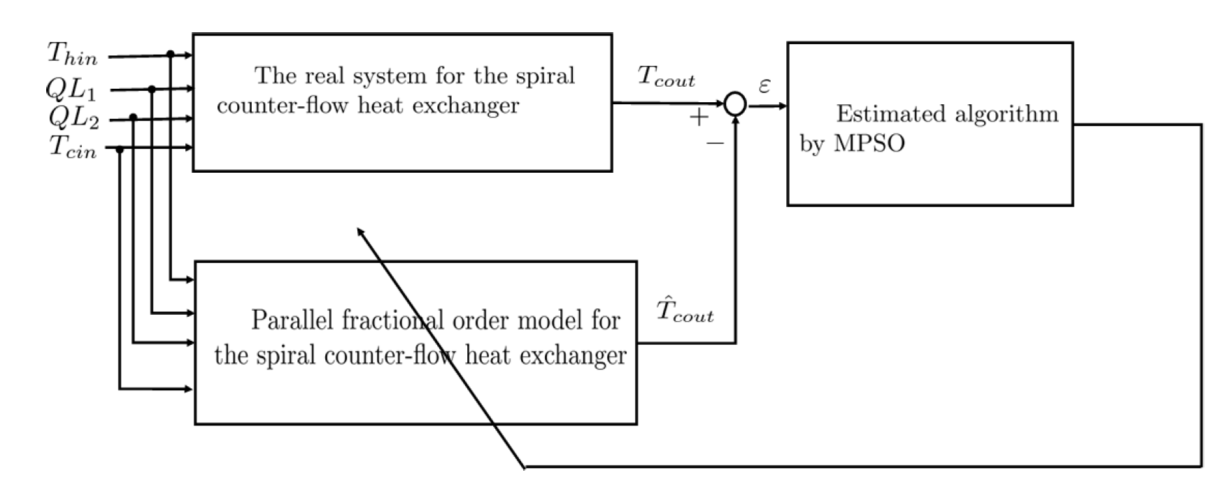
3.1. Parallel Fractional-Order Model for the Spiral Counter-Flow Heat Exchanger
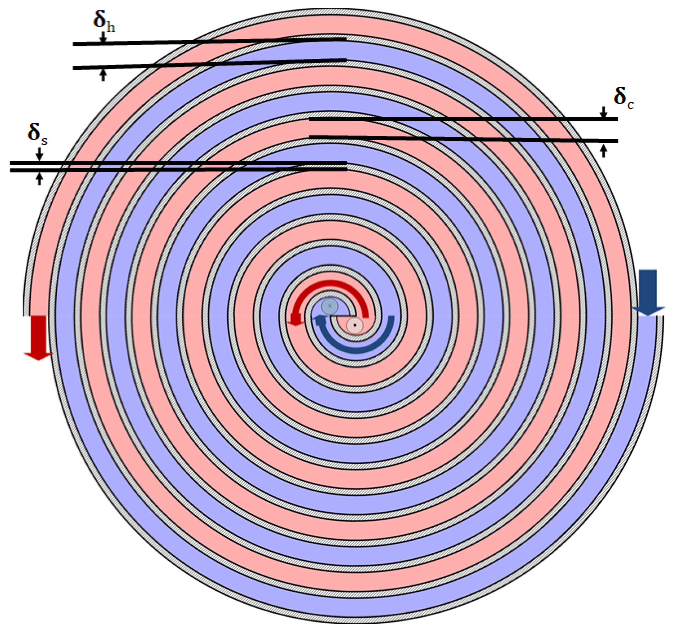
3.1.1. Fractional-Order Model for the Spiral Counter-Flow Heat Exchanger
3.1.2. Parallel Fractional-Order Model for the Spiral Counter-Flow Heat Exchanger
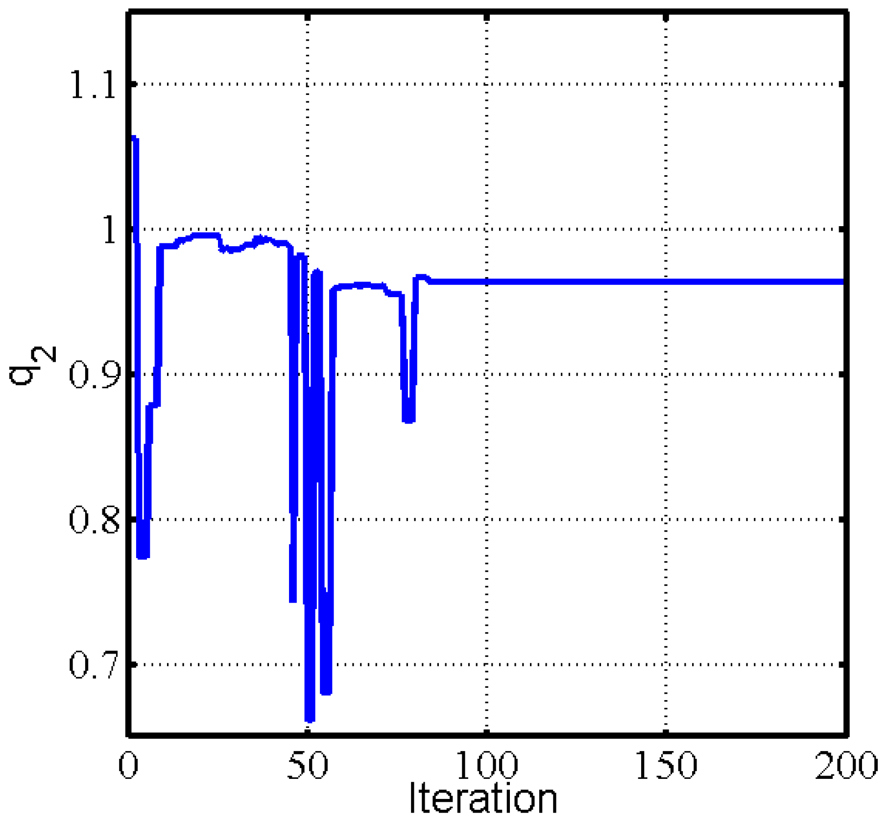
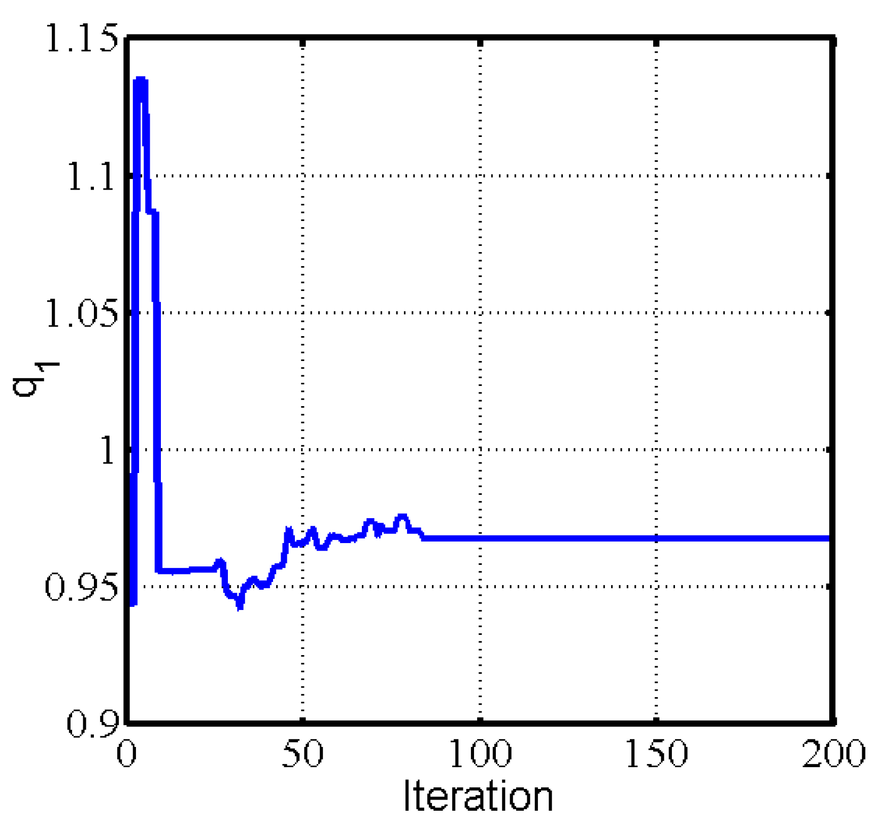
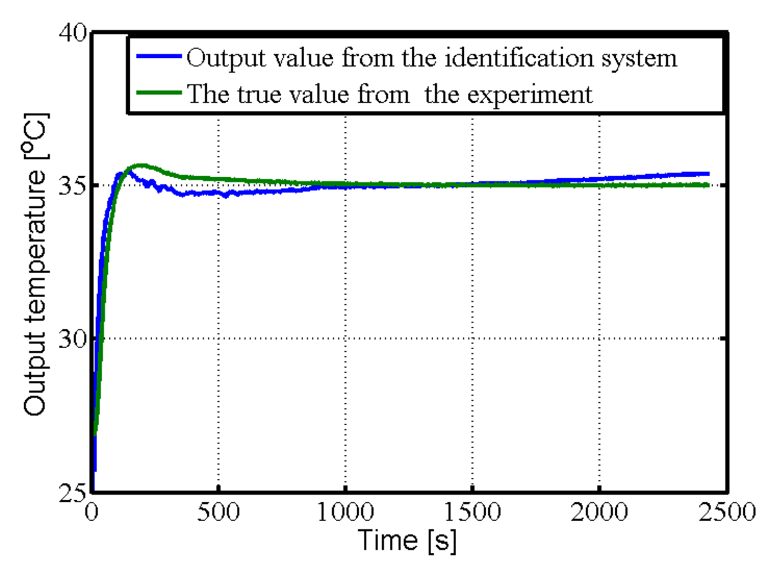
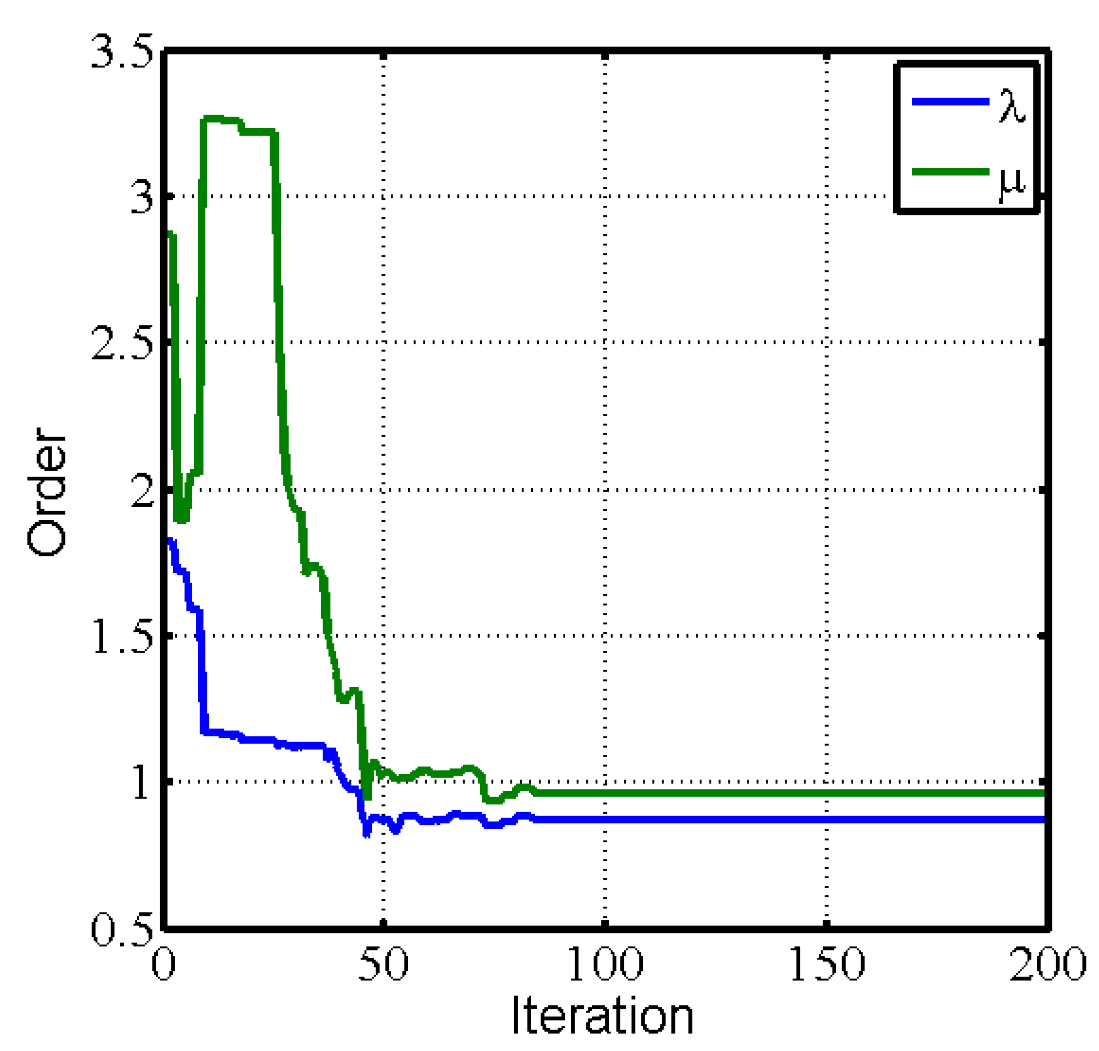
3.2. Parallel Fractional-Order Model Identification for the Spiral Heat Exchanger
- (1)
- Determine the searched spaces for the estimated model.
- (2)
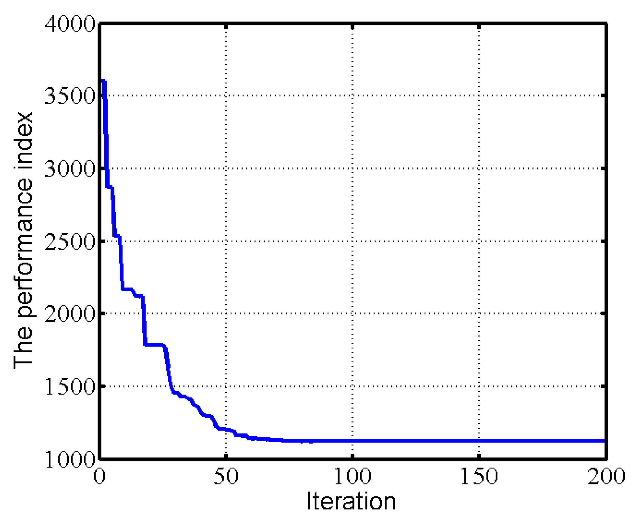
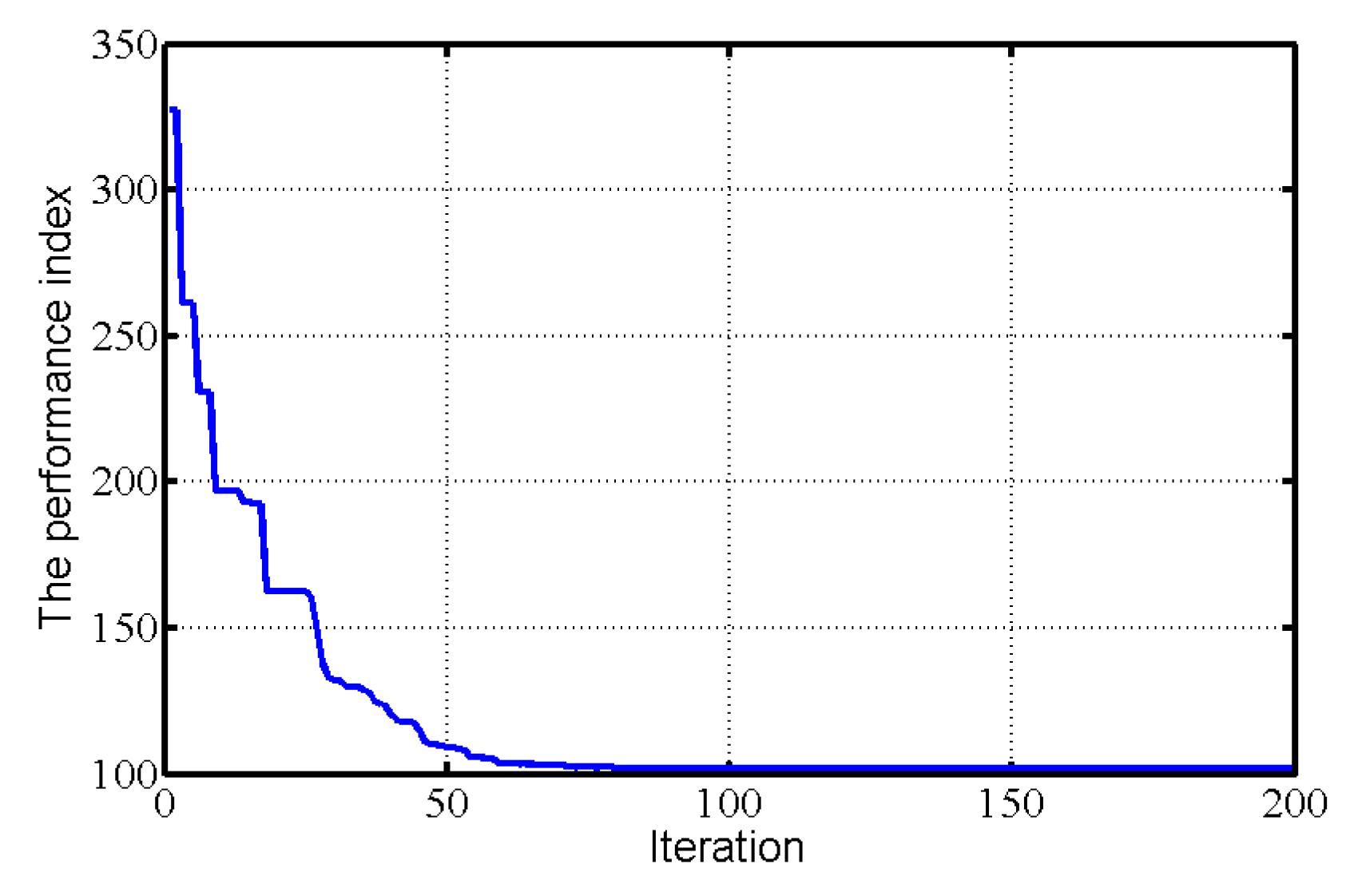
- Determine the performance index (evaluation function).
- (3)
- The parameters of the algorithm are initialized to generate random search vectors.
- (4)
- According to the steps of the PSO algorithm, the parameters in the parallel fractional-order model are identified.
- (5)
- The iteration is repeated until the performance index is satisfactory or the sum of iterations go up to a maximum of 200.
4. Operator-Based Fractional-Order PID Nonlinear Robust Control for the Spiral Heat Exchanger
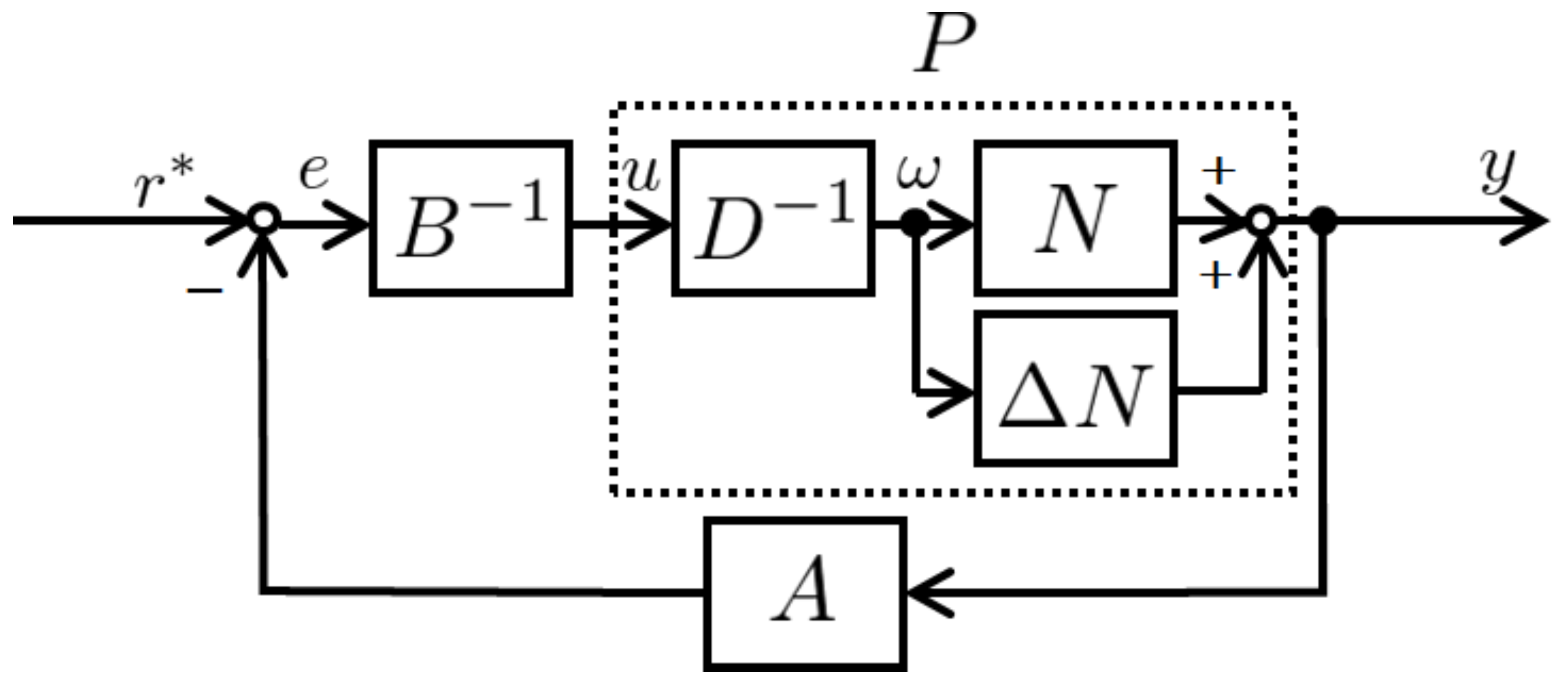
4.1. Parallel Fractional-Order Model for the Spiral Heat Exchanger with Uncertainties
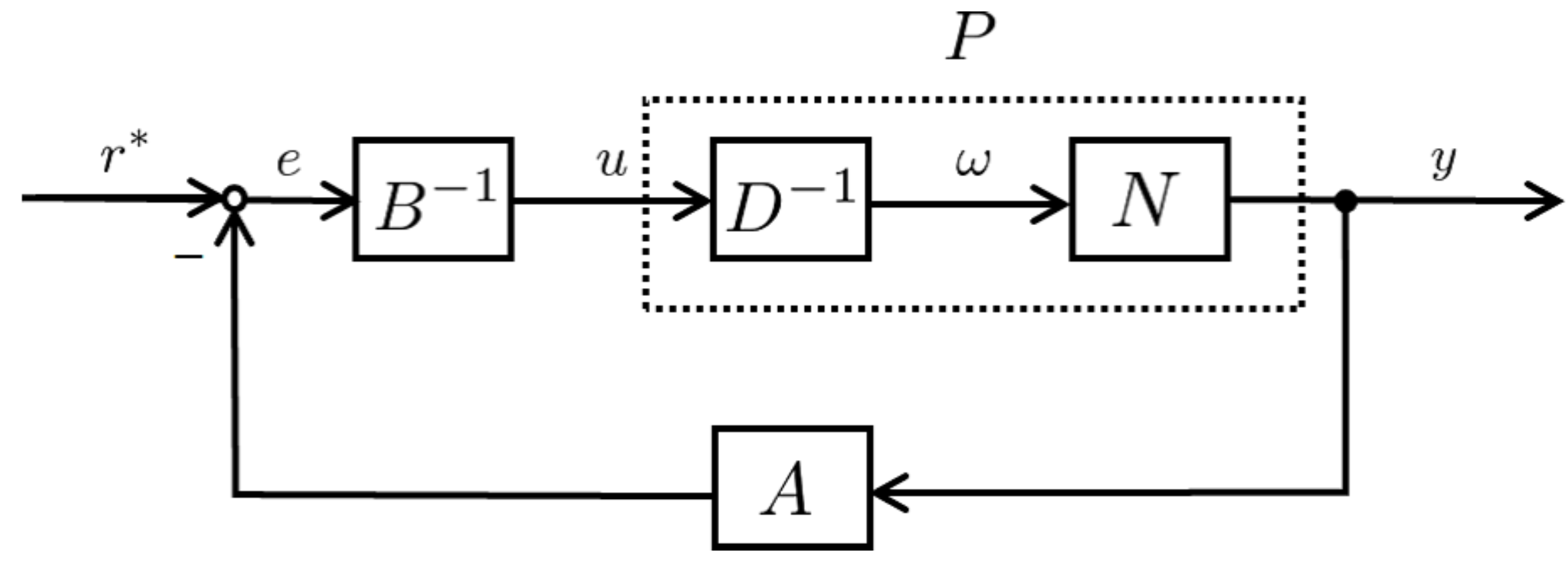
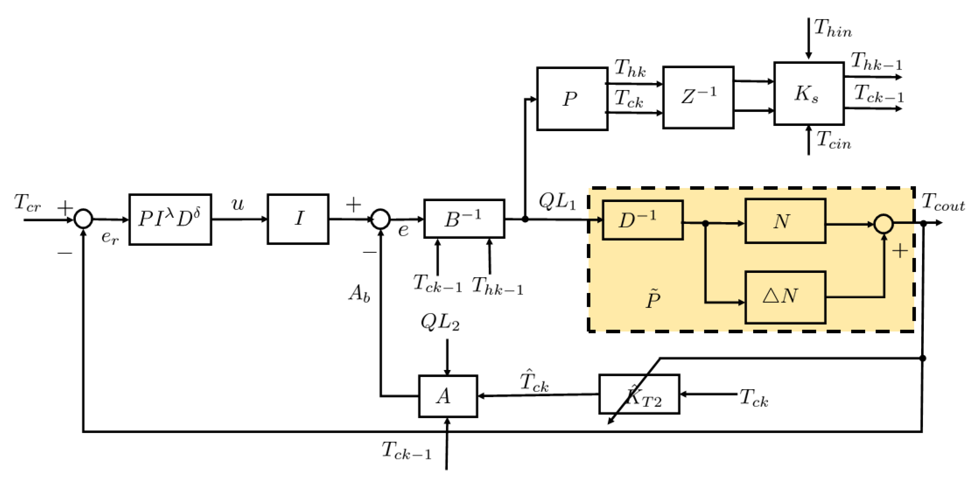
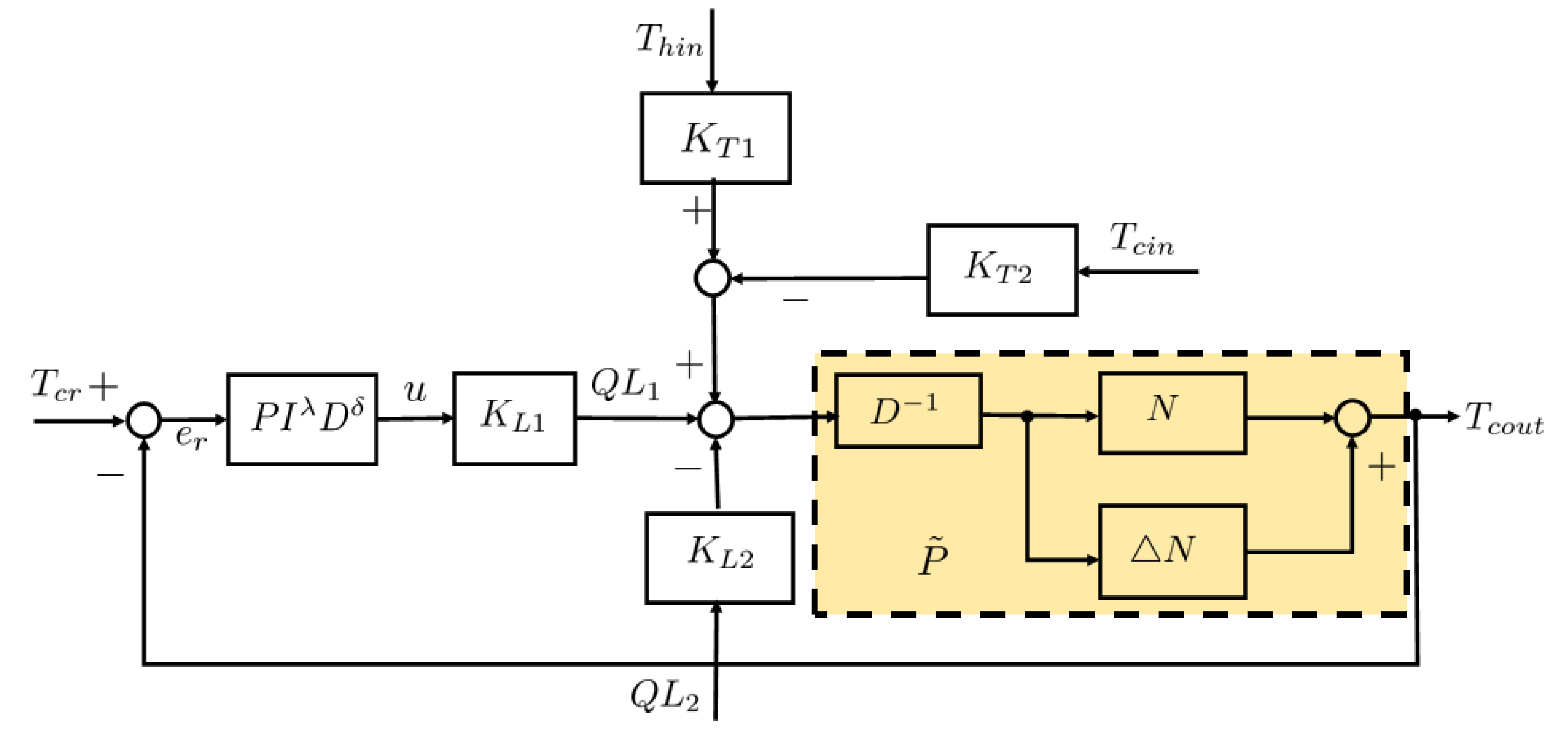
4.2. Operator-Based Controller Design
4.3. Fractional-Order Tracking Controller Design
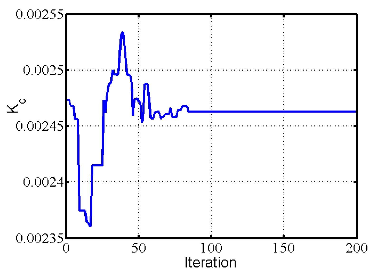
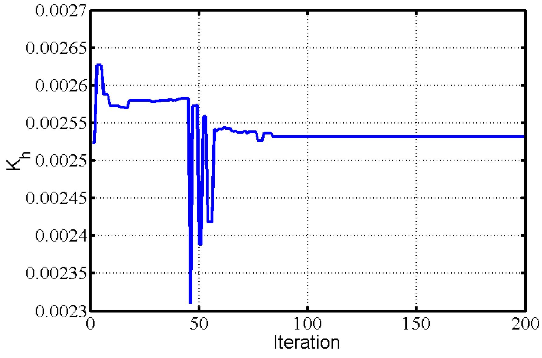
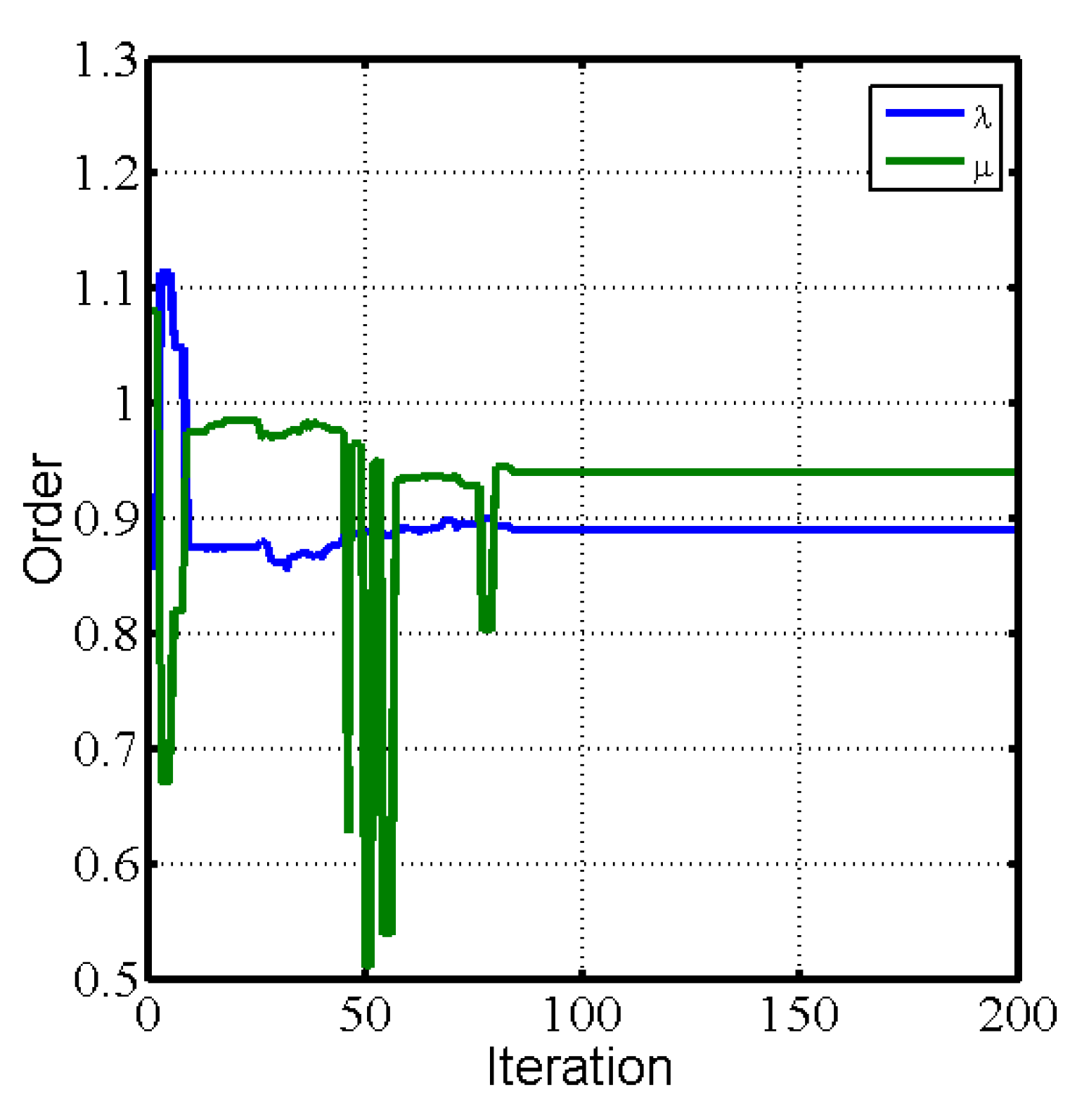
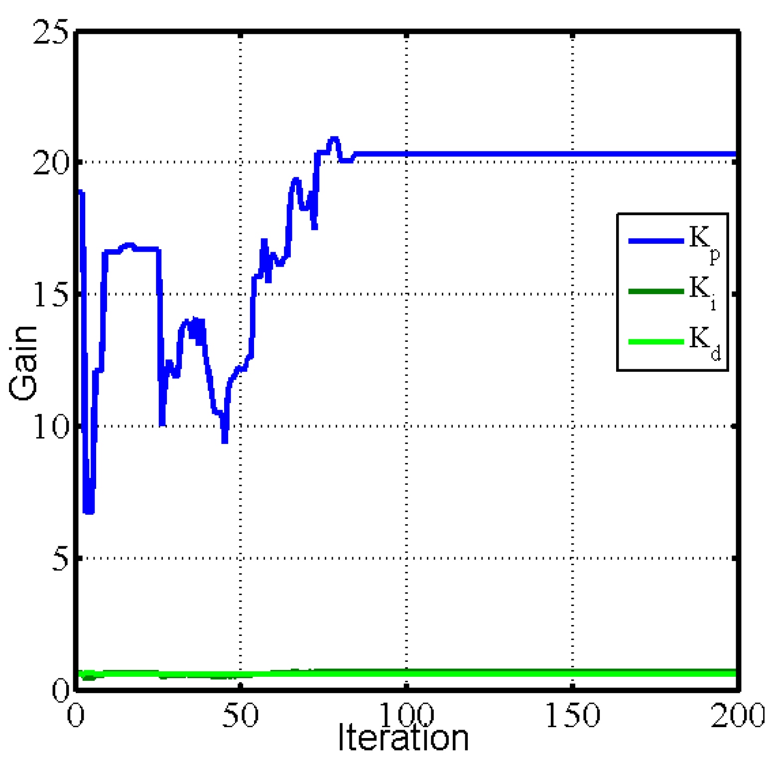
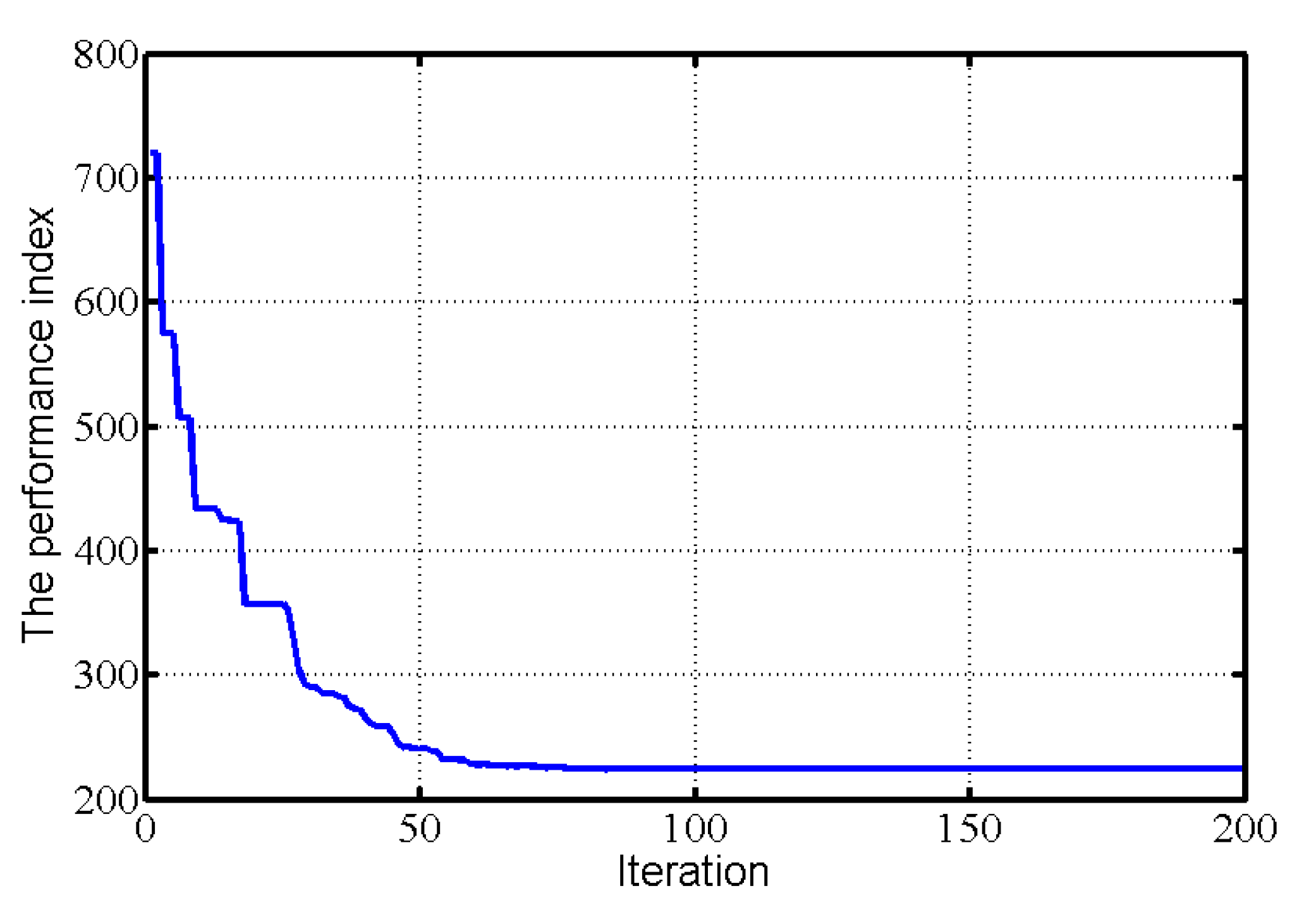
5. Parameter Optima for Fractional-Order PID Controller
- (1)
- Determine the searched spaces for the fractional-order PID controller.
- (2)
- Determine the performance index (evaluation function).
- (3)
- The parameters of the algorithm are initialized to generate random search vectors.
- (4)
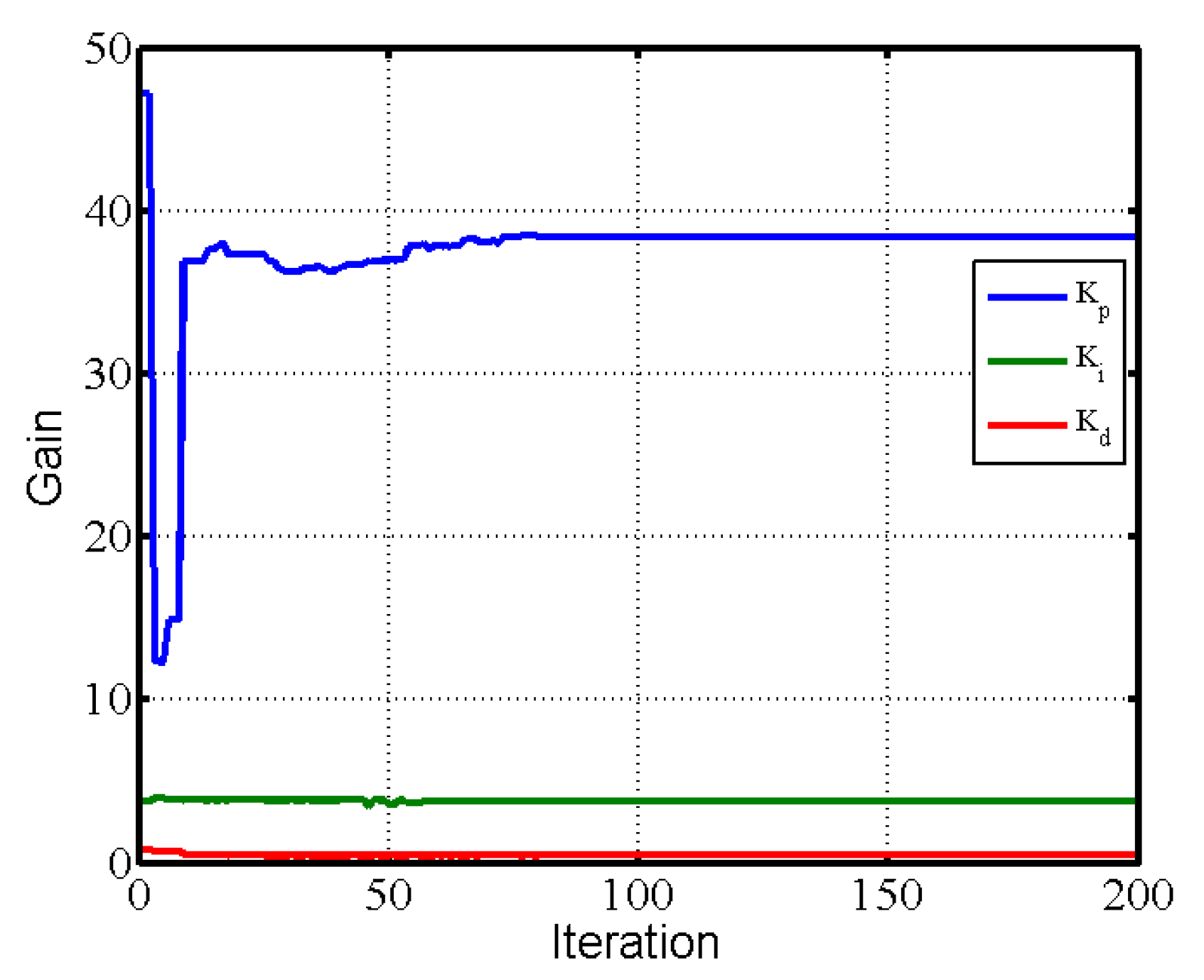
- According to the steps of the PSO algorithm, the parameters of fractional-order PID controller are identified.
- (5)
- The iteration is repeated until the performance index is satisfactory or the sum of iterations is maximal.
6. Analysis of Performance on Tracking and Antidisturbances for the Spiral Heat Exchanger with Disturbances
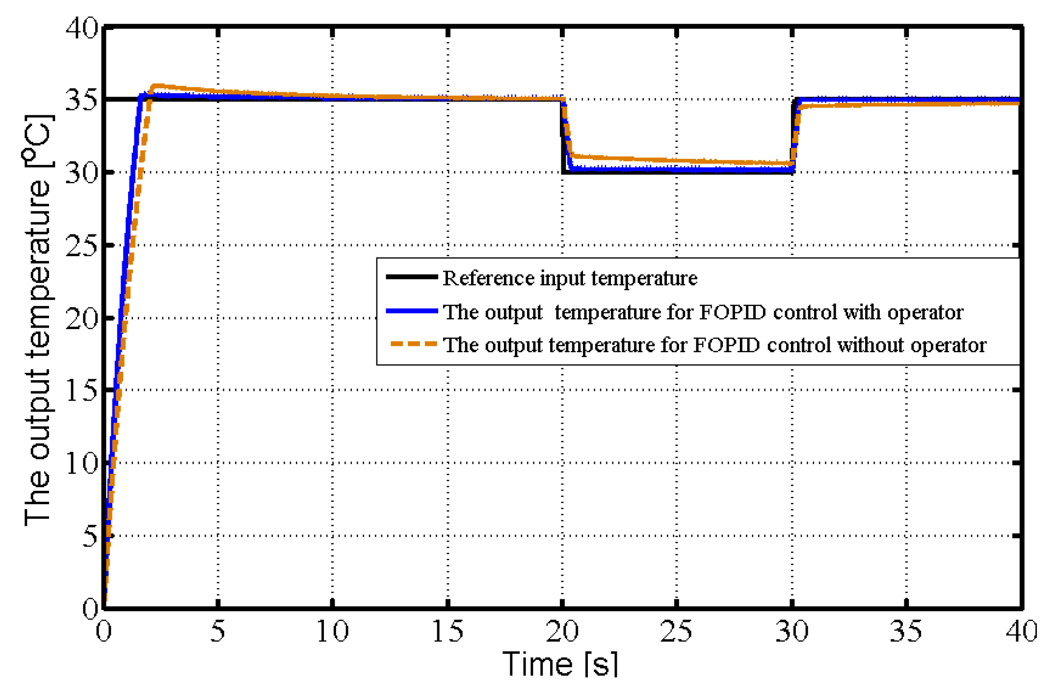
6.1. Tracking Performance for the Spiral Heat Exchanger with Disturbances
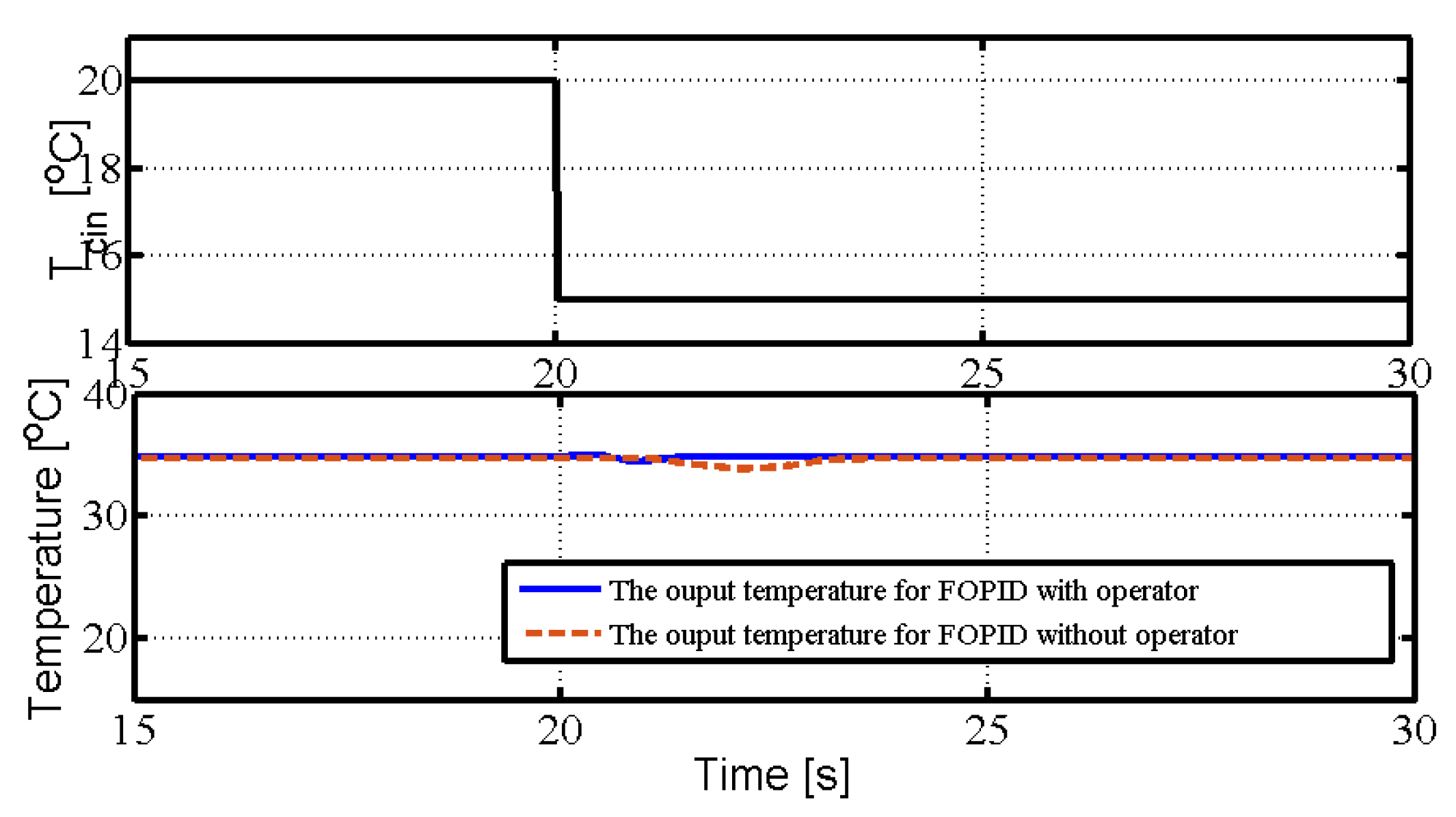
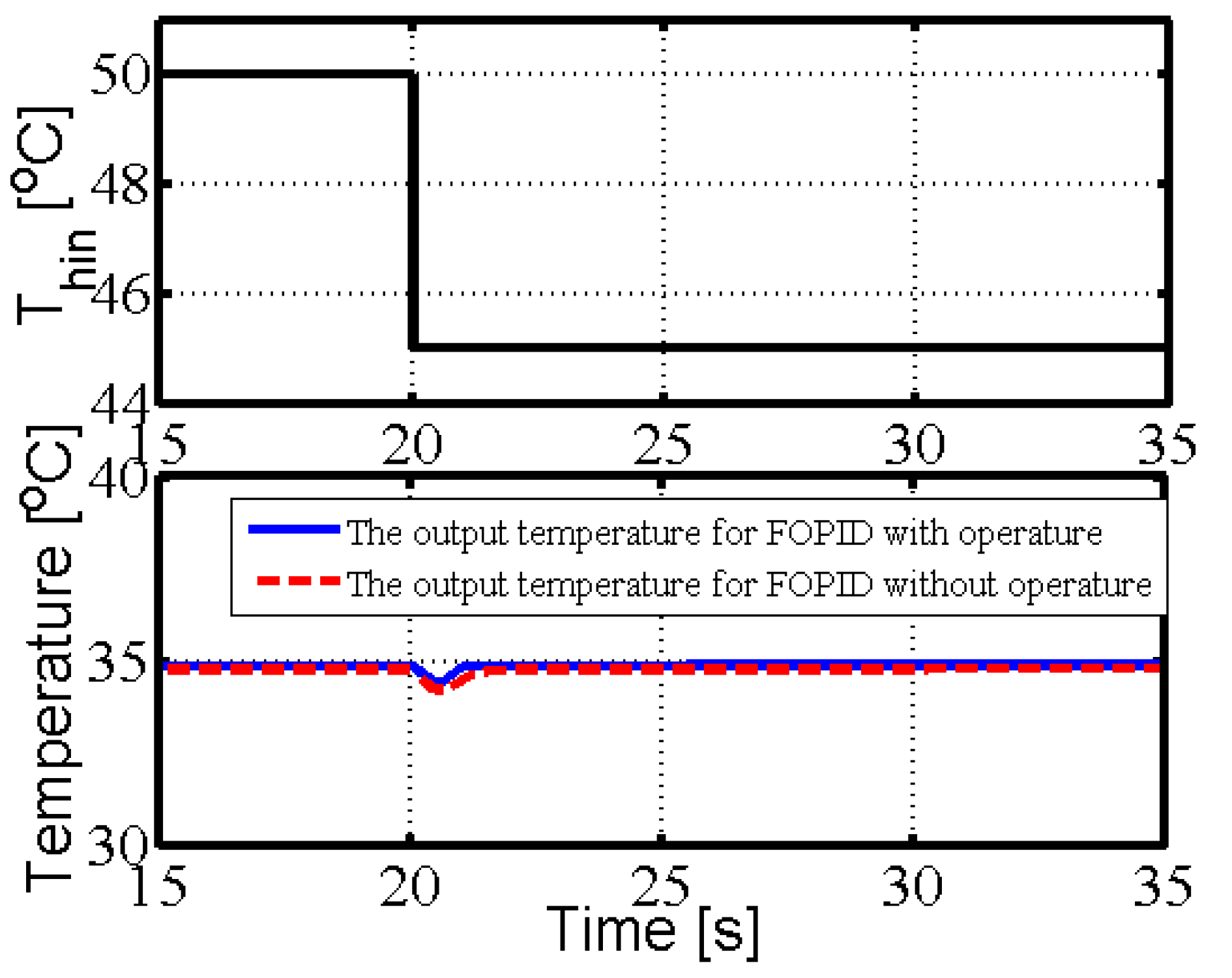
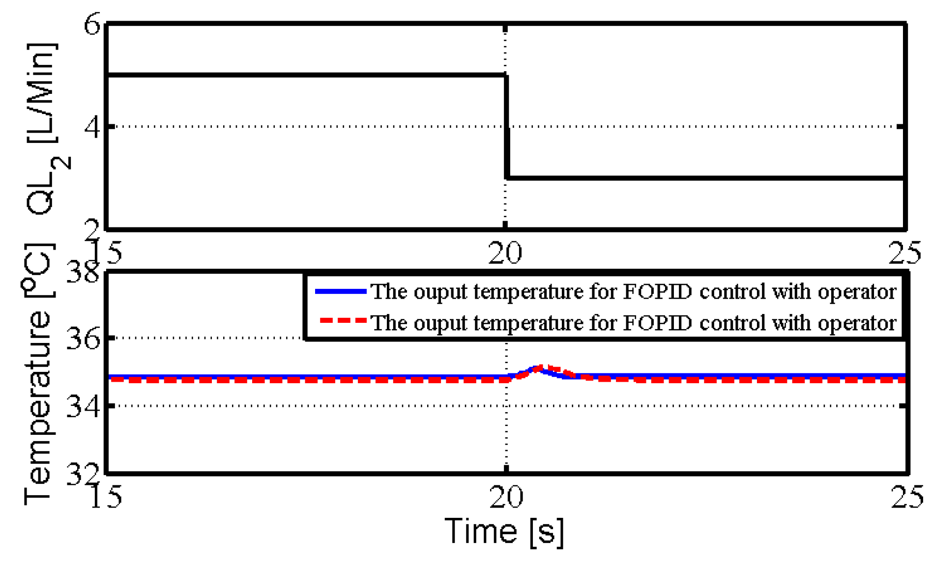
6.2. Antidisturbance Performance for the Spiral Heat Exchanger
7. Conclusions
Author Contributions
Funding
Data Availability Statement
Conflicts of Interest
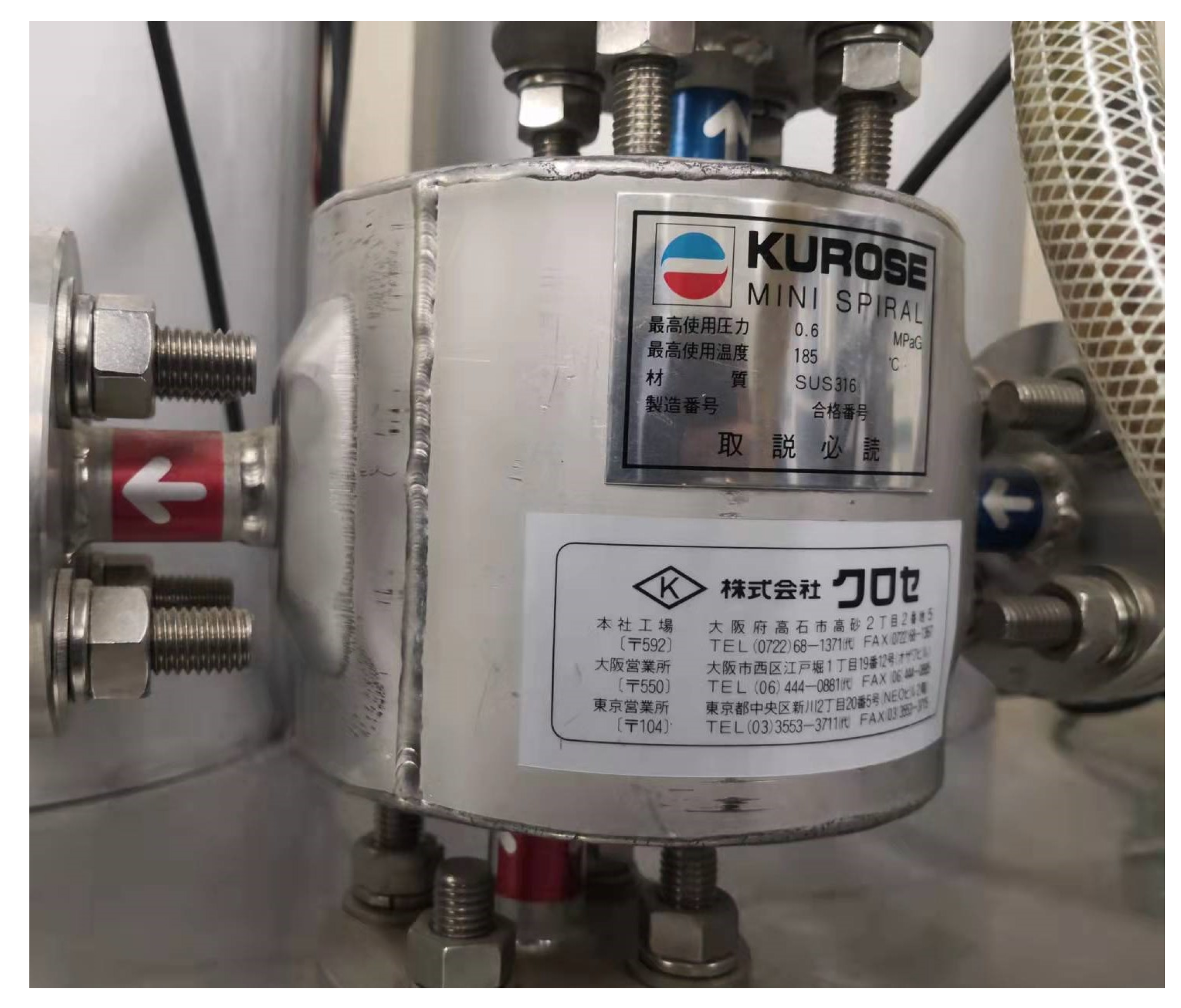
Appendix A. A Spiral Heat Exchanger Plant


| Meaning (Symbol) | Value |
|---|---|
| Spiral function’s parameter (a) | m/rad |
| Initial radius in high-temperature side (b) | 0.08 m |
| Width of the flow channel () | 0.005 m |
| Height of the spiral heat exchanger (Z) | 0.011 m |
References
- Kilbas, S.G.; Kilbas, A.A. Marichev, O.I. Fractional Integrals and Derivatives: Theory and Applications; Gordon and Breach Science Publishers: Philadelphia, PA, USA, 1993. [Google Scholar]
- Wang, J.C. Realizations of generalized warburg impedance with RC ladder networks and transmission lines. J. Electrochem. Soc. 1987, 134, 1915–1920. [Google Scholar] [CrossRef]
- Laskin, N. Fractional market dynamics. Phys. A Stat. Mech. Its Appl. 2000, 287, 482–492. [Google Scholar] [CrossRef]
- Ionescu, C.; Machado, J.T.; De Keyser, R. Fractional-order impulse response of the respiratory system. Comput. Math. Appl. 2011, 62, 845–854. [Google Scholar] [CrossRef]
- Badri, V.; Tavazoei, M.S. Fractional order control of thermal systems: Achievability of frequency-domain requirements. Nonlinear Dyn. 2014, 80, 1773–1783. [Google Scholar] [CrossRef]
- Podlubny, I. Fractional Differential Equations; Academic Press: San Diego, CA, USA, 1999. [Google Scholar]
- Ang, K.H.; Chong, G.C.Y.; Li, Y. PID control system analysis, design, and technology. IEEE Trans. Control. Syst. Technol. 2005, 13, 559–576. [Google Scholar]
- Tepljakov, A.; Baykant Alagoz, B.; Yeroglu, C. FOPID controllers and their industrial applications: A survey of recent results. Int. J. Innov. Eng. Technol. 2018, 51, 25–30. [Google Scholar]
- Xue, D. Fractional-Order Control Systems: Fundamentals and Numerical Implementations; De Gruyter: Berlin, Germany, 2017. [Google Scholar]
- Monje, C.A.; Vinagre, B.M.; Feliu, V.; Chen, Y. Tuning and auto-tuning of fractional order controllers for industry applications. Control Eng. Pract. 2008, 16, 798–812. [Google Scholar] [CrossRef]
- Liu, L.; Tian, S.; Xue, D.; Zhang, T.; Chen, Y. Continuous fractional order Zero Phase Error Tracking Control. ISA Trans. 2018, 75, 226–235. [Google Scholar] [CrossRef]
- Freeborn, T.J. A survey of fractional-order circuit models for biology and biomedicine. IEEE J. Emerg. Andselected Top. Circuits Syst. 2013, 3, 416–424. [Google Scholar] [CrossRef]
- Tapre, R.W.; Kaware, J.P. Review on heat transfer in spiral heat exchanger. Int. J. Sci. Res. 2015, 5, 370–376. [Google Scholar]
- Metta, V.R.; Konijeti, R.; Dasore, A. Thermal design of spiral plate heat exchanger through numerical modelling. Int. J. Mech. Eng. Technol. 2018, 9, 736–745. [Google Scholar]
- Khorshidi, J.; Heidari, S. Design and construction of a spiral heat exchanger. Adv. Chem. Eng. Sci. 2016, 6, 201–208. [Google Scholar] [CrossRef]
- Sathiyan, S.; Rangarajan, M. An experimental study of spiral-plate heat exchanger for nitrobenzene-water two-phase system. Bulg. Chem. Commun. 2010, 42, 205–209. [Google Scholar]
- Liu, Z.; Sun, N.; Wu, Y.; Fang, Y. Nonlinear sliding mode tracking control of underactuated tower cranes. Int. J. Control Autom. Syst. 2021, 19, 1065–1077. [Google Scholar] [CrossRef]
- Tuan, L.A. Neural observer and adaptive fractional-order backstepping fast-terminal sliding-mode control of RTG cranes. IEEE Trans. Ind. Electron. 2021, 68, 434–442. [Google Scholar] [CrossRef]
- Shen, P.Y.; Schatz, J.; Caverly, R.J. Passivity-based adaptive trajectory control of an underactuated 3-DOF overhead crane. Control Eng. Pract. 2021, 112, 104834. [Google Scholar] [CrossRef]
- Dong, G.; Deng, M. Operator & Fractional Order Based Nonlinear Robust Control for a Spiral Counter-flow Heat Exchanger with Uncertainties and Disturbances. Machines 2022, 10, 335. [Google Scholar]
- Deng, M.; Wen, S.; Inoue, A. Operator-based robust nonlinear control for a Peltier actuated process. Meas. Control J. Inst. Meas. Control 2011, 44, 116–120. [Google Scholar] [CrossRef]
- Wang, A.; Deng, M. Robust nonlinear multivariable tracking control design to a manipulator with unknown uncertainties using operator-based robust right coprime factorization. Trans. Inst. Meas. Control 2013, 35, 788–797. [Google Scholar] [CrossRef]
- Wen, S.; Deng, M.; Inoue, A. Operator-based robust nonlinear control for gantry crane system with soft measurement of swing angle. Int. J. Model. Identif. Control 2012, 16, 86–96. [Google Scholar] [CrossRef]
- Deng, M.; Inoue, A.; Soitiro Goto, G. Operator based thermal control of an aluminum plate with a Peltier device. Int. J. Innov. Comput. Inf. Control 2008, 4, 3219–3229. [Google Scholar]
- Gao, X.; Deng, M. Tracking performance improvement for operator based nonlinear robust control of wireless power transfer systems with uncertainties. Int. J. Control Autom. Syst. 2019, 17, 545–554. [Google Scholar] [CrossRef]
- Wu, Y.; Deng, M. Operator-based robust nonlinear optimal vibration control for an L-shaped arm driven by linear pulse motor. Int. J. Control Autom. Syst. 2017, 15, 2026–2033. [Google Scholar] [CrossRef]
- Dong, G.; Deng, M. Operator Based Fractional Order Control System for a Spiral Heat Exchanger with Uncertainties. In Proceedings of the 2021 International Conference on Advanced Mechatronic Systems, Tokyo, Japan, 9–12 December 2021; pp. 242–247. [Google Scholar]
- Kennedy, J.; Eberhart, R. Particle Swarm Optimization. In Proceedings of the ICNN’95—International Conference on Neural Networks, Perth, WA, Australia, 27 November–1 December 1995; pp. 1942–1948. [Google Scholar]
- Pal, D.; Verma, P.; Gautam, D.; Indait, P. Improved optimization technique using hybrid ACO-PSO. In Proceedings of the 2016 2nd International Conference on Next Generation Computing Technologies, Dehradun, India, 14–16 October 2016; pp. 277–282. [Google Scholar]
- Hendtlass, T. WoSP: A multi-optima particle swarm algorithm. In Proceedings of the IEEE Congress on Evolutionary Computation, Edinburgh, UK, 2–5 September 2005; pp. 727–734. [Google Scholar]
- Dong, G.; Deng, M. GPU based modelling and analysis for parallel fractional order derivative model of the spiral-plate heat exchanger. Axioms 2021, 10, 344. [Google Scholar] [CrossRef]


Publisher’s Note: MDPI stays neutral with regard to jurisdictional claims in published maps and institutional affiliations. |
© 2022 by the authors. Licensee MDPI, Basel, Switzerland. This article is an open access article distributed under the terms and conditions of the Creative Commons Attribution (CC BY) license (https://creativecommons.org/licenses/by/4.0/).
Share and Cite
Dong, G.; Deng, M. Operator-Based Fractional-Order Nonlinear Robust Control for the Spiral Heat Exchanger Identified by Particle Swarm Optimization. Electronics 2022, 11, 2800. https://doi.org/10.3390/electronics11172800
Dong G, Deng M. Operator-Based Fractional-Order Nonlinear Robust Control for the Spiral Heat Exchanger Identified by Particle Swarm Optimization. Electronics. 2022; 11(17):2800. https://doi.org/10.3390/electronics11172800
Chicago/Turabian StyleDong, Guanqiang, and Mingcong Deng. 2022. "Operator-Based Fractional-Order Nonlinear Robust Control for the Spiral Heat Exchanger Identified by Particle Swarm Optimization" Electronics 11, no. 17: 2800. https://doi.org/10.3390/electronics11172800
APA StyleDong, G., & Deng, M. (2022). Operator-Based Fractional-Order Nonlinear Robust Control for the Spiral Heat Exchanger Identified by Particle Swarm Optimization. Electronics, 11(17), 2800. https://doi.org/10.3390/electronics11172800