Article

Research on an Efficient Deep-Hole Application Method for Liquid Fertilizer Based on Alternate Drilling

College of Engineering, Northeast Agricultural University, Harbin 150030, China
*
Author to whom correspondence should be addressed.
Processes 2022, 10(7), 1320; https://doi.org/10.3390/pr10071320
Submission received: 6 June 2022 / Revised: 28 June 2022 / Accepted: 1 July 2022 / Published: 5 July 2022
(This article belongs to the Section Sustainable Processes)

Abstract

:
Liquid fertilizers are mainly applied by spraying liquid fertilizer on the surface of crop leaves and by deep openings between rows. The first causes considerable environmental pollution, and the second can easily cause to damage the root system of crops. In this study, corn crops were taken as the study object and an efficient deep-hole application method for liquid fertilizer based on alternate drilling was proposed. The needle body is driven by the spur gear wheel system in a caving mechanism to puncture holes alternately in a vertical posture and high-speed punctures are implemented with less disturbance to the soil. The cylindrical hollow cam of the mechanism is controlled so that the fertilizer needle sprays fertilizer when injected into soil and stops injecting when pulled out of the soil. Based on the bench test, fertilizer injecting performance and energy saving performance of the differential two-way fertilizer supply distribution device were analyzed and the head loss for energy saving value is 2.1, 3.1, and 5.5 m. Based on numerous field tests, the puncture track, hole width, and hole spacing are analyzed under different puncture speeds. Field tests were carried out according to a quadratic orthogonal rotating combination design and the results show that when the fertilization depth for agronomic requirements is 80 mm and the machine work speed and forward speed are 127 r min−1 and 1.40 m s−1, respectively, the hole width is 39.9 mm, the hole spacing is 320 mm. The efficient deep-hole application method for liquid fertilizer based on alternate drilling can provide support for data analysis and theoretical design of liquid fertilizer deep application technology for corn crops.

1. Introduction

Corn is an important food crop, with more than 177 million hectares planted worldwide each year [1,2,3]. It is mainly cultivated in the United States, China, Brazil, and Argentina. Liquid fertilizer application methods mainly include foliar injecting, drip irrigation, and deep application [1,2,3,4]. Foliar spray fertilization is to spray liquid fertilizer rapidly on the surface of crop leaves by injecting a system, which is fast and effective in operation. Although the foliar spray fertilization method is efficient, it contributes to environmental pollution [5]. The drip irrigation fertilization method has a high fertilizer utilization rate and little environmental pollution, but the cost is higher and not suitable for large field operations [6,7]. Deep furrow opening can reduce the volatilization of nitrogen but the furrowing tends to cause damage to crop roots [8,9].
Liquid fertilizer hole deep application technology can improve soil structure, increase soil organic matter, and improve soil microbial activity while saving liquid fertilizer [10,11,12,13,14]. Plant roots can rapidly absorb the nitrogen, phosphorus, and potassium elements in liquid fertilizer to improve crop yield and ensure grain quality [9,15,16,17,18].
Womac and Tomkins [19] used a crank-slider mechanism to drive an injecting needle to perforate the soil and stop injecting. Da Silva et al. [20] used a cam-crank rocker combination mechanism to drive the fertilizer injecting needle to achieve a cavity application function on sugarcane crops at fixed points. These two application methods could ensure the vertical posture of the injecting needles during the process of entering and leaving the soil, and the hole opening could meet the smaller target, but the drive unit of the drill adopted a “lever mechanism movement form” to achieve liquid fertilizer application, which limited the movement characteristics and efficiency of the mechanism itself and made it difficult to meet the requirements of efficient and deep liquid fertilizer application.
Wang et al. [21] designed a crank rocker mechanism to achieve a deep-hole liquid fertilizer application function with a hole-driving component. Due to the same “lever mechanism movement form”, the deep-hole liquid fertilizer application efficiency was low, and the hole opening was large. On this basis, Wang et al. [22] designed a ShiYefeiJi-2 (SYJ-2) deep-hole liquid fertilizer application spreader. The drive system of the drilling mechanism adopted a fully elliptical gear planetary system, which improved the drilling efficiency and could better meet the deep application requirements of liquid fertilizer holes; however, the nonvertical posture of the needle body and the positive structural form of drilling led to large holes on the soil surface and mechanical damage to the crops.
Therefore, in this context, this paper proposes an efficient deep-hole application method for liquid fertilizer based on an alternate drilling method. This research study includes conceptual design, experimental evaluation, and analysis.

2. Materials and Methods

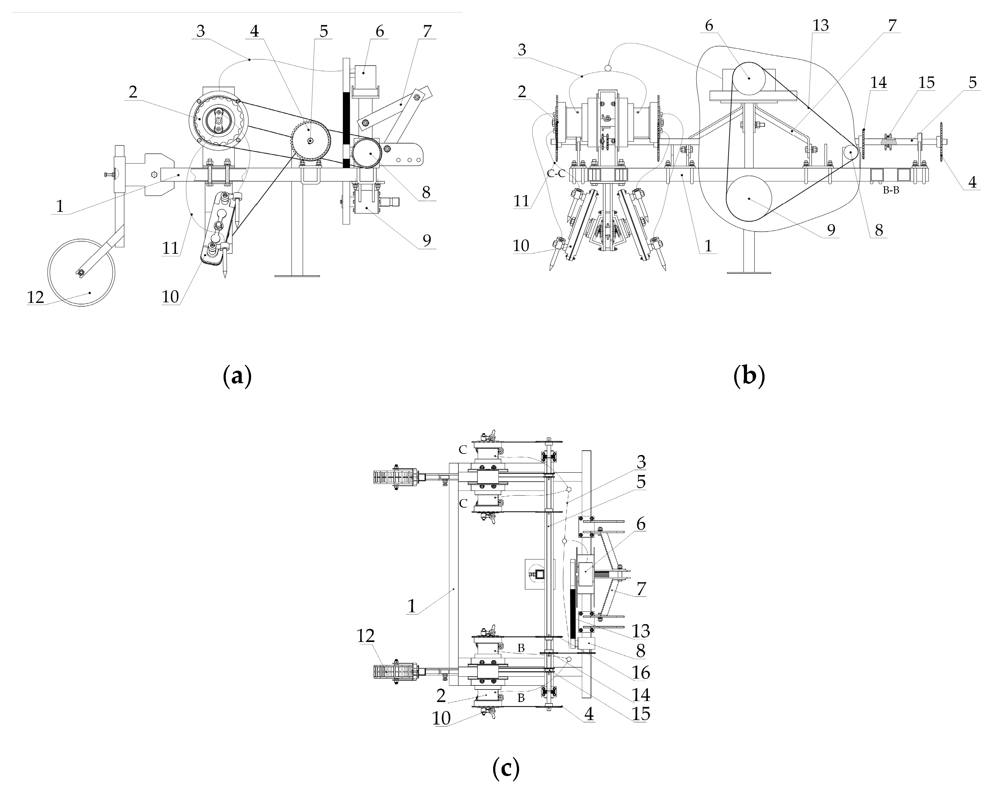
2.1. Machine Structure

The deep-hole liquid fertilizer applicator is shown in Figure 1.
The front and rear parts of the frame assembly are installed with a three-point suspension frame assembly and ground wheel assembly, respectively, and the liquid fertilizer pump, worm gear reducer, power input shaft assembly, main drive shaft, liquid fertilizer injecting control mechanism, and drilling mechanism are installed on the frame assembly in turn. The main drive belt is mounted on the worm gear reducer, the liquid fertilizer pump, and the power input shaft assembly. The main liquid fertilizer delivery line connects the liquid fertilizer pump to the liquid fertilizer injecting control mechanism. The liquid fertilizer feeder line connects the liquid fertilizer application control mechanism to the drilling mechanism. Sprocket A, sprocket C, sprocket B, and sprocket D are fixed on the main drive shaft from the outside to the inside, and a chain connects the worm gear reducer to sprocket B. Sprocket A and sprocket D are connected to the liquid fertilizer application control mechanism through the chain, and sprocket C is connected to the cavity tying mechanism through the chain.

2.2. Working Principle of the System

During the operation, the deep-hole liquid fertilizer applicator is connected to the tractor by the three-point suspension assembly, which is pulled forward by the tractor; the PTO (Power Take Off) of the tractor is connected to the power input shaft assembly, and the rotating power input shaft assembly is driven by the worm gear reducer and liquid fertilizer pump through the main drive belt. The reducer rotates the main drive shaft driven by sprocket B. The main drive shaft drives sprocket A, sprocket C, and sprocket D to rotate synchronously. Sprocket A and sprocket D drive the liquid fertilizer injecting control mechanism to rotate and work, feeding the hole applicator into the hole tying mechanism via the liquid fertilizer feeding branch pipe. Sprocket C drives the drilling mechanism for rotary motion and finally completes the hole applicator’s inclined vertical posture drilling and liquid fertilizer hole-deepening operation. The body of the cavity applicator is shown in Figure 2. The dimensions of this prototype system are (W: 2600, H: 975, L: 1710), and four rows of operations can be performed simultaneously at a time.

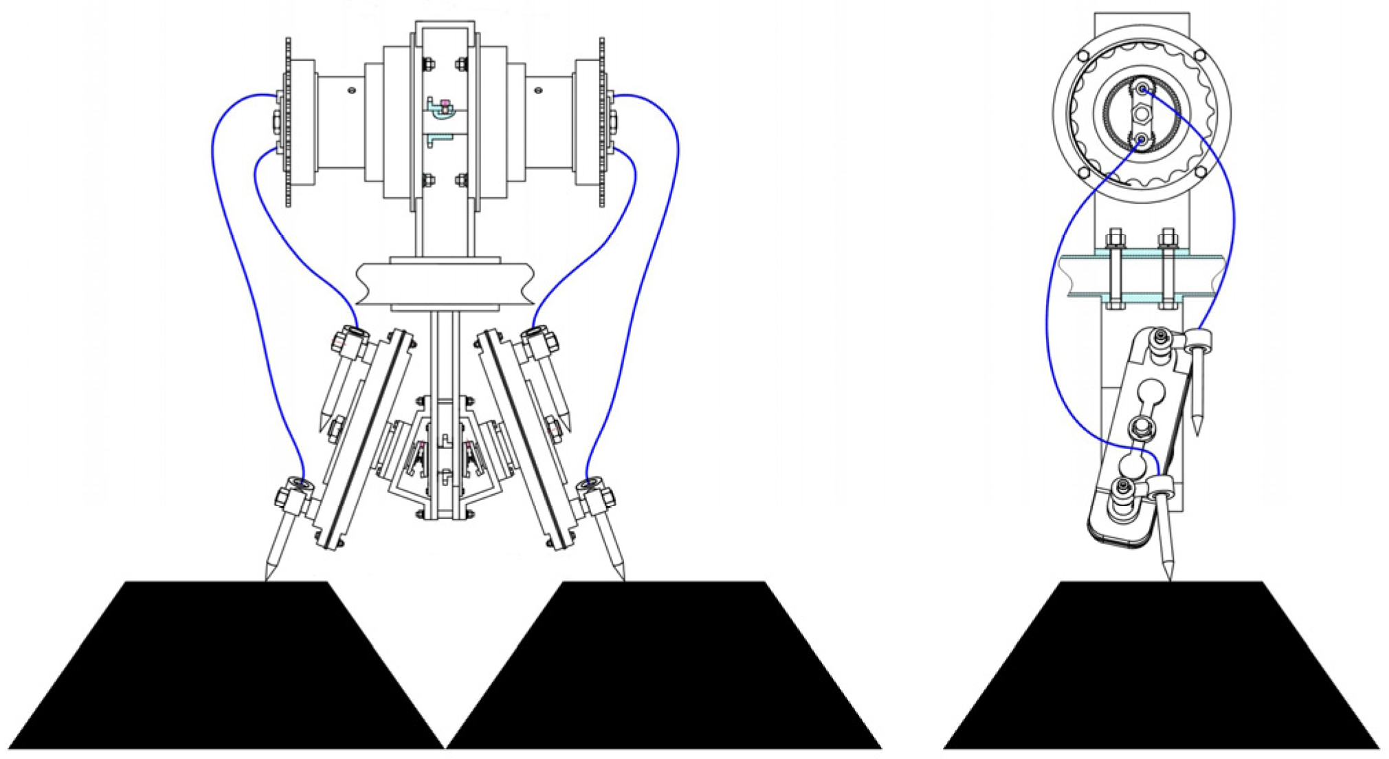
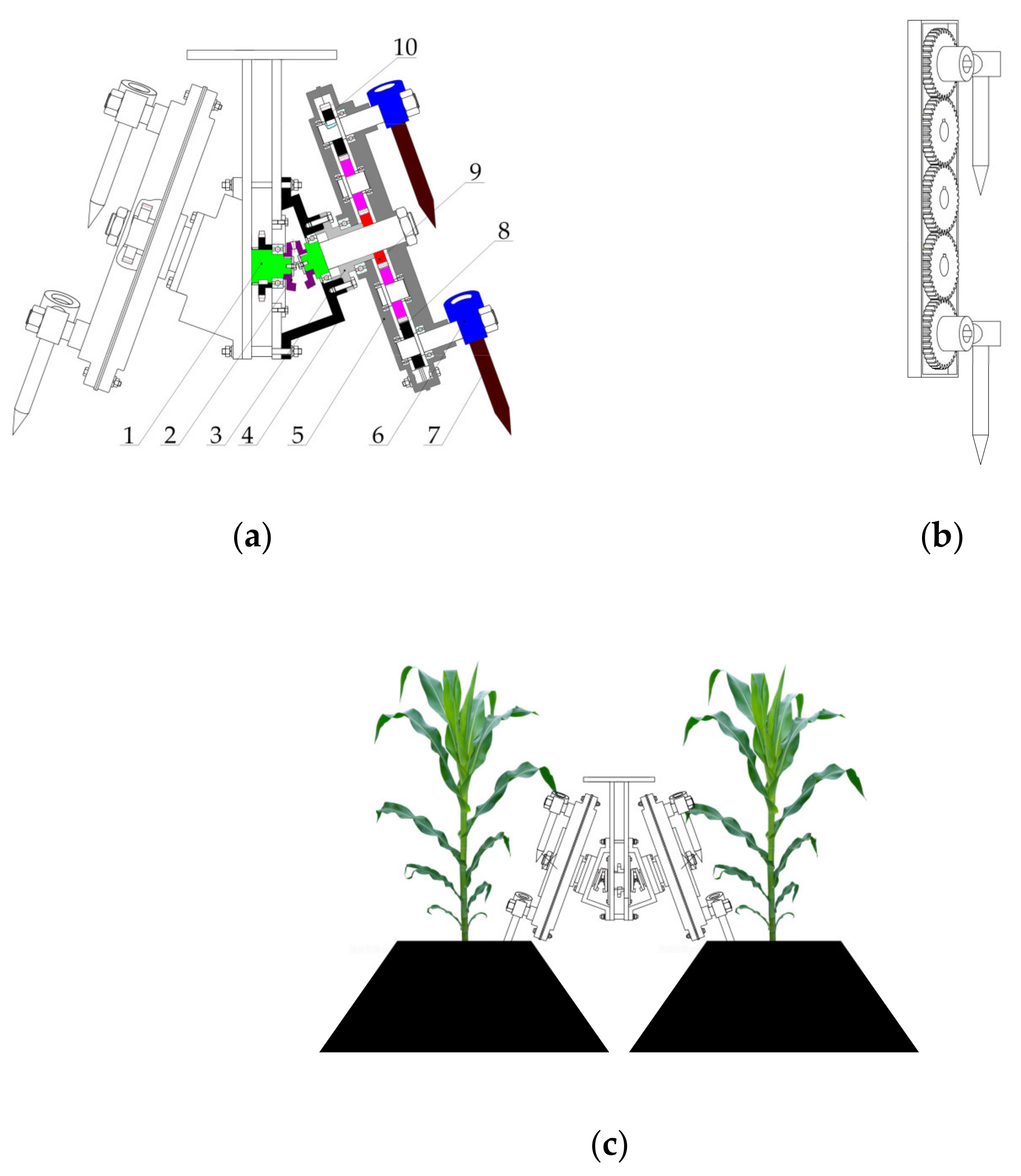
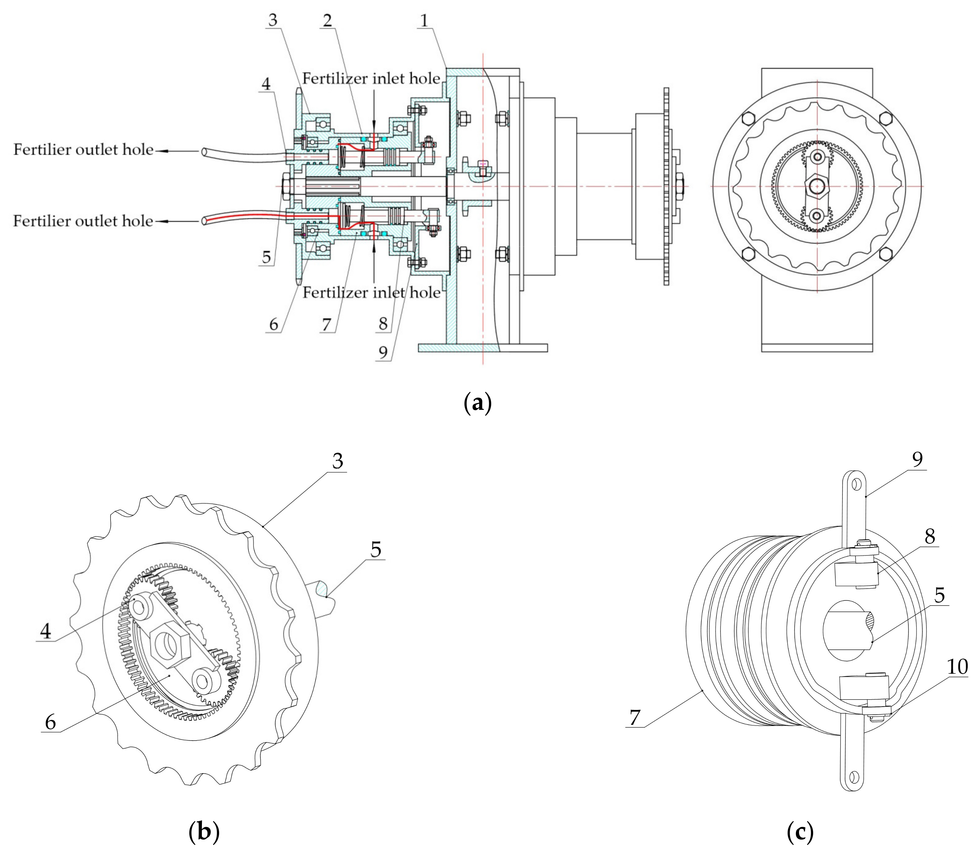
2.3. Structure and Working Principle of Drilling Mechanism

To achieve high efficiency and reduce crop damage, the drilling mechanism is designed, as shown in Figure 3. The tie point mechanism is mainly composed of five equal spur gears, a drive housing, a flange, a bevel gear, an outer housing, a rocker arm, a fertilizer spray needle, and other parts.
The sprocket shaft and the sun wheel shaft are driven by a bevel gear, which runs through the sun wheel and is solidly attached to the drive housing. The flange and sun wheel are fixed to the outer housing and remain stationary with respect to the ground. The drive housing can rotate around the center of rotation of the flange, as shown in Figure 3a.
The five spur gears are arranged in equal order inside the drive housing cavity, and the rocker arm and the solid body of the needle are mounted on the axis line of the upper and lower planetary wheels, respectively. The initial installation angle of the fertilizer spray needle needs to meet vertical to the ground, as shown in Figure 3b.
When working, the external power source drives the sprocket shaft to rotate; then, under the action of the bevel gear, the sun wheel shaft drives the housing around the flange centerline for rotational motion under the action of spur gear galaxy transmission, forcing the fertilizer needle to always ensure vertical attitude movement. As the mechanism presents the inclined structure form, it reduces the mechanical collision damage, as shown in Figure 3c.

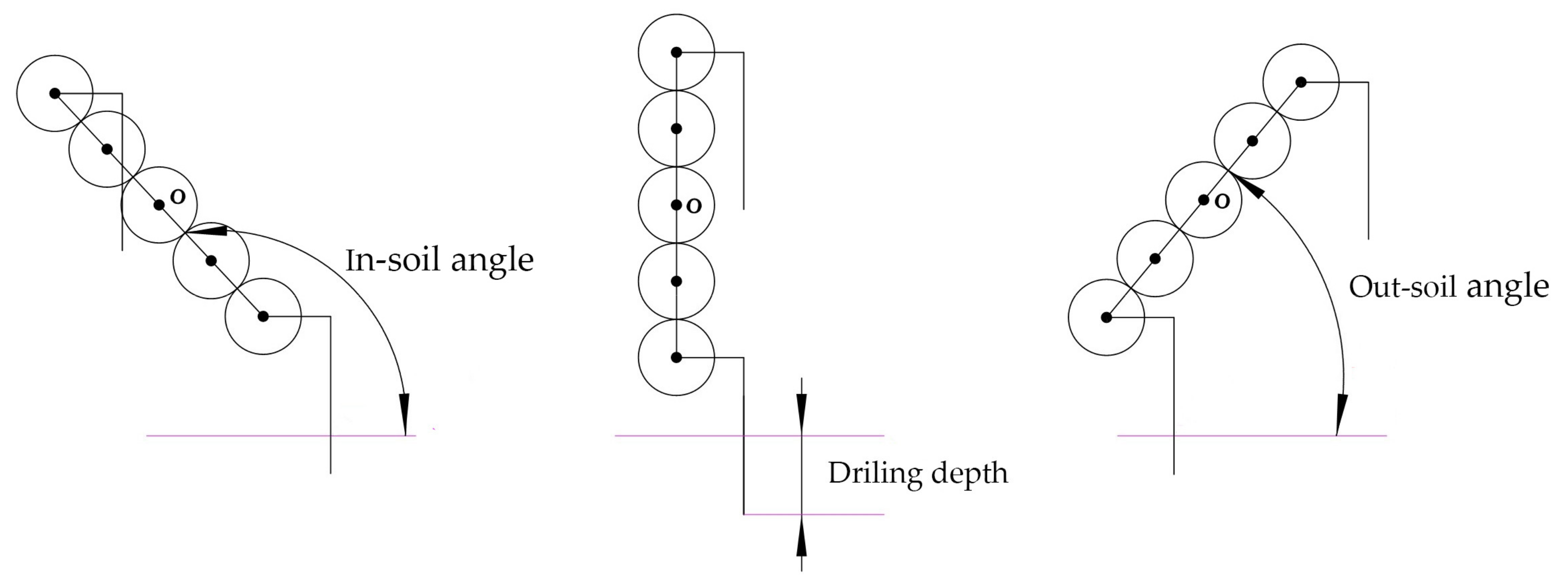
2.4. Parameters of Drilling Mechanism

A full spur gear planetary system can achieve the perpendicular and motion characteristics of the fertilizer needle [23,24,25], and its structural sketch is shown in Figure 4.
The Line OA (The red line in Figure 4) is the main influencing factor in determining the longitudinal size of the drive housing. If the longitudinal size is too large, the kinetic performance of the mechanism becomes poor, and the driving force becomes large; if the longitudinal size is too small, interference can occur between the adjacent fertilizer needles, and the hole spacing becomes small. To ensure a corn plant inter-row of 320 mm and good dynamics, the Line OA should be between 120–150 mm. In this paper, the Line OA was 136 mm, and the spur gear knuckle curve was used to obtain a diameter of 68 mm. To avoid driving the shell to scrape the soil and to achieve the agronomic requirements of deep fertilization depth, the design size of the needle needs to be slightly larger than the spur gear knuckle curve radius of 34 mm with an 80 mm hole depth; thus, the shell wall thickness was added at the size, thus setting the length of the needle at 140 mm.

2.5. Structure and Working Principle of Drilling Mechanism

The liquid fertilizer application control mechanism is designed to achieve the goal of efficient and low-loss fertilizer delivery. The mechanism can be directly connected to the hose interface of the fertilizer injecting needle, which reduces the loss of fertilizer during the fertilizer delivery process [26,27]. The mechanism mainly consists of a sprocket shaft housing, a sprocket shaft, a spindle sleeve, a sub sleeve, a planetary wheel, an inner gear ring, a top bar, an outer housing, and a cylindrical hollow cam [28,29,30].
The outer housing is solidly attached to the sprocket shaft housing and the sprocket shaft is connected through the sprocket shaft housing to the sub shaft sleeve and spindle sleeve inside the housing. One side of the spindle sleeve is bonded to the other side of the sub sleeve.
The other end of the spindle sleeve has two planetary wheels symmetrically inlaid on the circumference and the other end of the secondary sleeve has two top rods symmetrically inlaid on the circumference. The inner gear ring is on the outer shell and engages with the planetary wheels and the main sleeve, planetary wheels and inner gear ring form the differential wheel system.
The cylindrical hollow cam is seated in the housing and mated with the top rod, while the sleeve, top rod, and cylindrical hollow cam form the cam mechanism. A two-dimensional model of the mechanism is shown in Figure 5.
When working, the external power source drives the sprocket shaft and inner gear ring. The sprocket shaft drives the spindle sleeve, and the sub sleeve for rotational motion, the movement of the planetary wheel inside the spindle sleeve is in the form of a combined motion of rotation around the axis line and rotation of the sprocket axis line and the operation of the differential wheel system makes the angular velocity of the planetary wheel zero.
The cylindrical hollow cam mechanism makes the top rod in the sub shaft sleeve rotate and reciprocate linearly on the cylindrical hollow convex contour [31,32], ensuring the opening and closing of the fertilizer drain hole while rotating synchronously with the planetary wheel.
The liquid fertilizer flows in from the inlet hole at a certain pressure. When the top bar moves from the pulling track to the returning track of the cylindrical hollow cam, the liquid fertilizer flows out from the outlet hole and is applied into the soil by the injecting needle through the hose. The red curve in Figure 5 shows the liquid fertilizer flow trajectory; when the top bar moves to the near rest stage, the top bar closes, and the liquid fertilizer stops being sprayed.

2.6. Fertilizer Injecting Control Mechanism Parameters

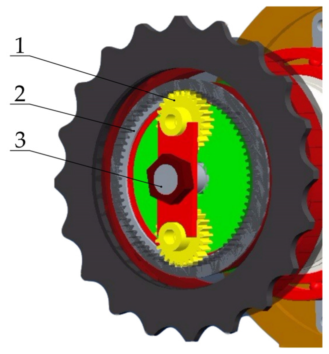
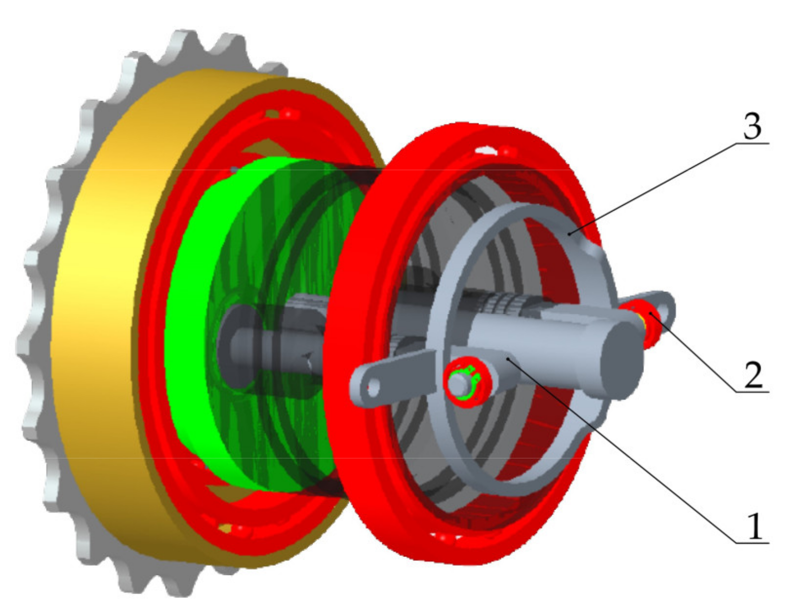
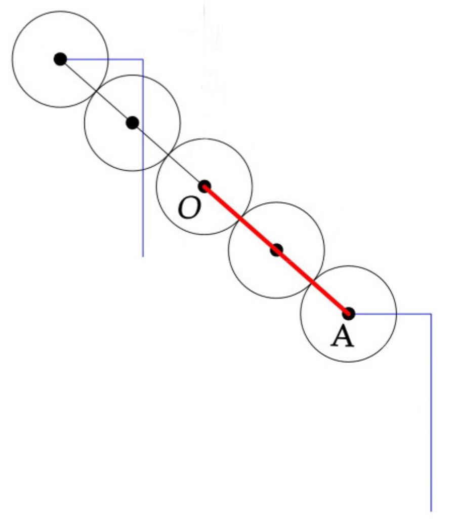
2.6.1. Differential Wheel Mechanism

To make the movement form of the needle outlet hose interface of the liquid fertilizer injecting mechanism consistent, a double planetary wheel-internal gear ring differential wheel system is adopted. According to the requirements of the needle movement characteristics of the drilling mechanism, a double planetary wheel-internal gear ring differential wheel system is adopted to meet the requirements of zero angular velocity of the injecting mechanism and the movement matching of rotation around the sprocket axis line to solve the mutual interference of the connecting hoses between the liquid fertilizer injecting control mechanism and the drilling mechanism and the “self-tightening” problem [31,32], as shown in Figure 6.
The number of teeth in the inner ring and the planetary wheel are 75 and 25, respectively, so that the angular velocity of the planetary wheel is zero, the ratio of angular velocity between the sprocket axis, and the inner ring is 3:2. The three-dimensional structure of the mechanism is shown in Figure 7.

2.6.2. Cylindrical Hollow Cam Mechanism

Fertilizer injecting needles are required to spray fertilizer while in the soil and stop injecting when out of the soil in one working cycle. According to the overall structural dimensions of the liquid fertilizer injecting control mechanism, the average cylindrical radius of the cylindrical hollow cam mechanism was determined to be 50 mm, the maximum stroke was 6 mm, and the top roller radius was 10 mm.
The angle between the inlet and outlet of the fertilizer needle and the horizontal plane was used to determine the angle of motion of the cylindrical hollow cam’s thrust stroke as 47°, and the angle of motion of the return stroke was 39.6°, as shown in Figure 8. The three-dimensional model of the cam mechanism is obtained, as shown in Figure 9.

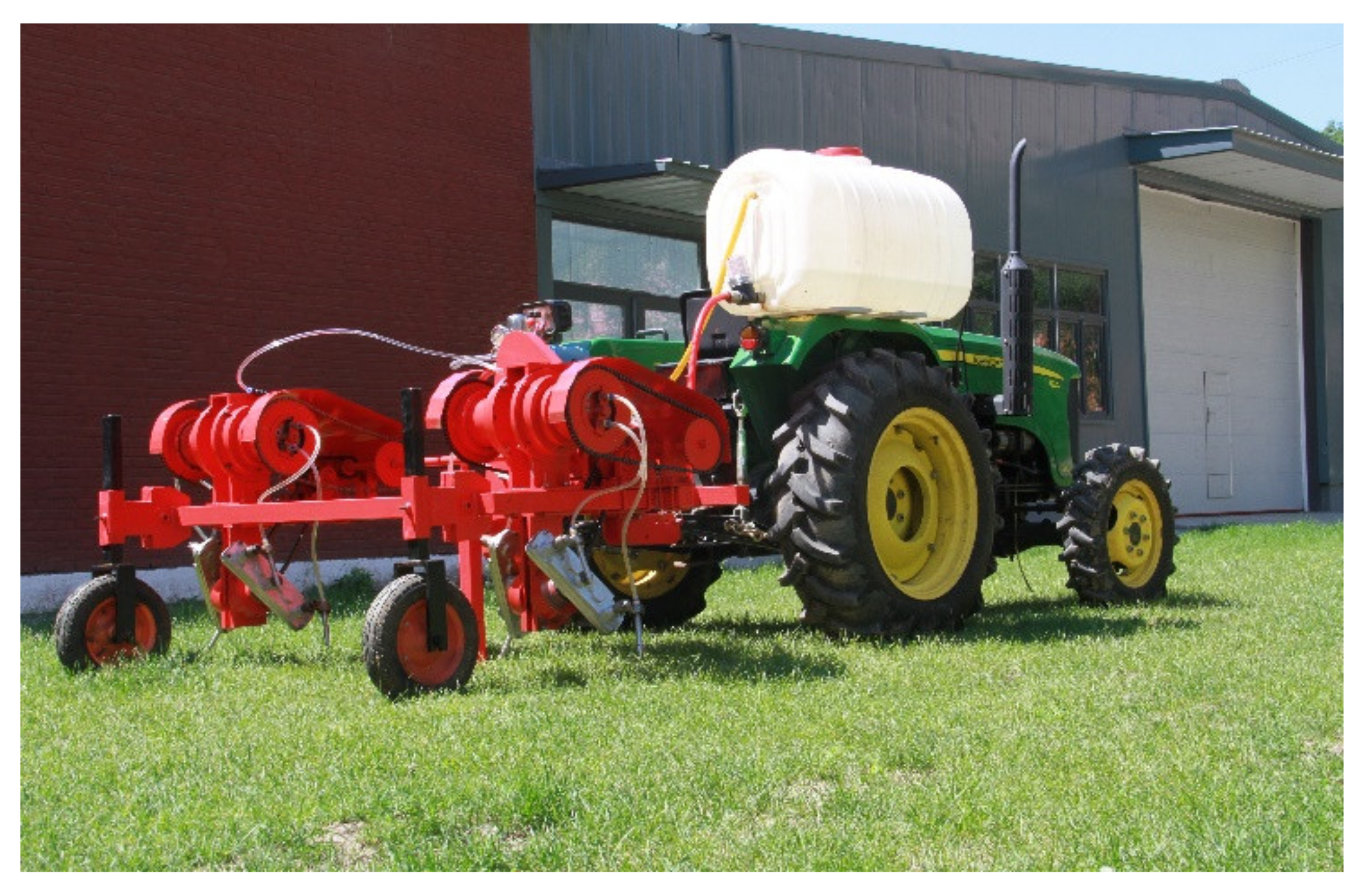
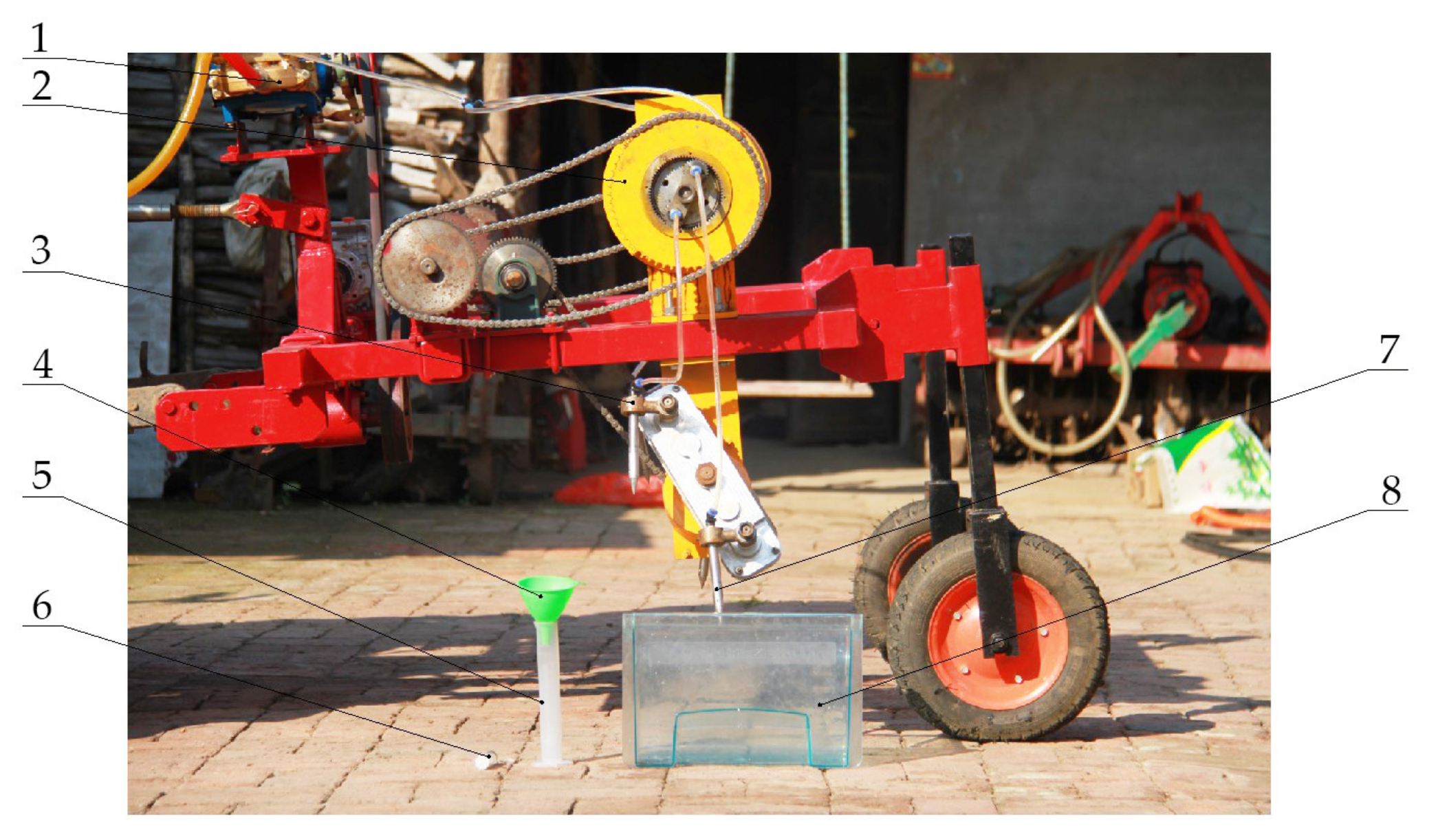
2.7. Traction Equipment

This study uses John Deere (Ningbo, Zhejiang, China) Agricultural Machinery Co., Ltd. 280 model tractor, the tractor has good performance, operating ground clearance, and a number of advantages, suitable for corn fertilization operations, a machine supporting power of 28 horsepower, drive form for the rear wheel drive, ground clearance height of 310 mm, front wheel specifications for 4.00–16, rear wheel specifications for 9.5–24, suitable for corn crop fertilizing operations.

2.8. Bench Test

To analyze the fertilizer injecting performance of this fertilizer sprayer, we conducted bench tests on the differential two-way fertilizer supply distribution device and the drilling mechanism. The test was conducted on 6 April 2020 in an open space outside the agricultural and animal husbandry laboratory of Northeast Agricultural University, Xiangfang District, Harbin City, Heilongjiang Province (126°43′48″ N, 45°44′56″ E). To analyze the working performance and the rationality of the design of the distribution device, fertilizer injecting performance and energy saving tests were conducted. The main equipment used for the tests is shown in Table 1 and Figure 10.

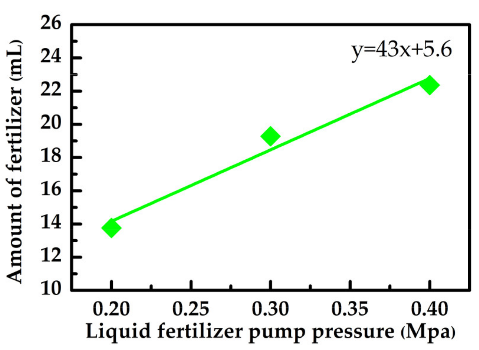
2.8.1. Fertilizer Application Volume and Liquid Fertilizer Pump Pressure Bench Test

To explore the relationship between fertilizer application volume and liquid fertilizer pump pressure, the pressure value of the liquid fertilizer pump was predicted when the agronomic requirement of 20–30 mL of fertilizer application volume was reached. In the test, the liquid fertilizer pump pressure was selected as the variable and the output shaft speed as the quantitative to see how the fertilizer application volume varied with the liquid fertilizer pump pressure. The speed of the differential bi-directional fertilizer distribution device was set at 75 r min−1 to ensure the same speed as the cavity tying mechanism, and the three levels of liquid fertilizer pump pressure were 0.2, 0.3, and 0.4 MPa.

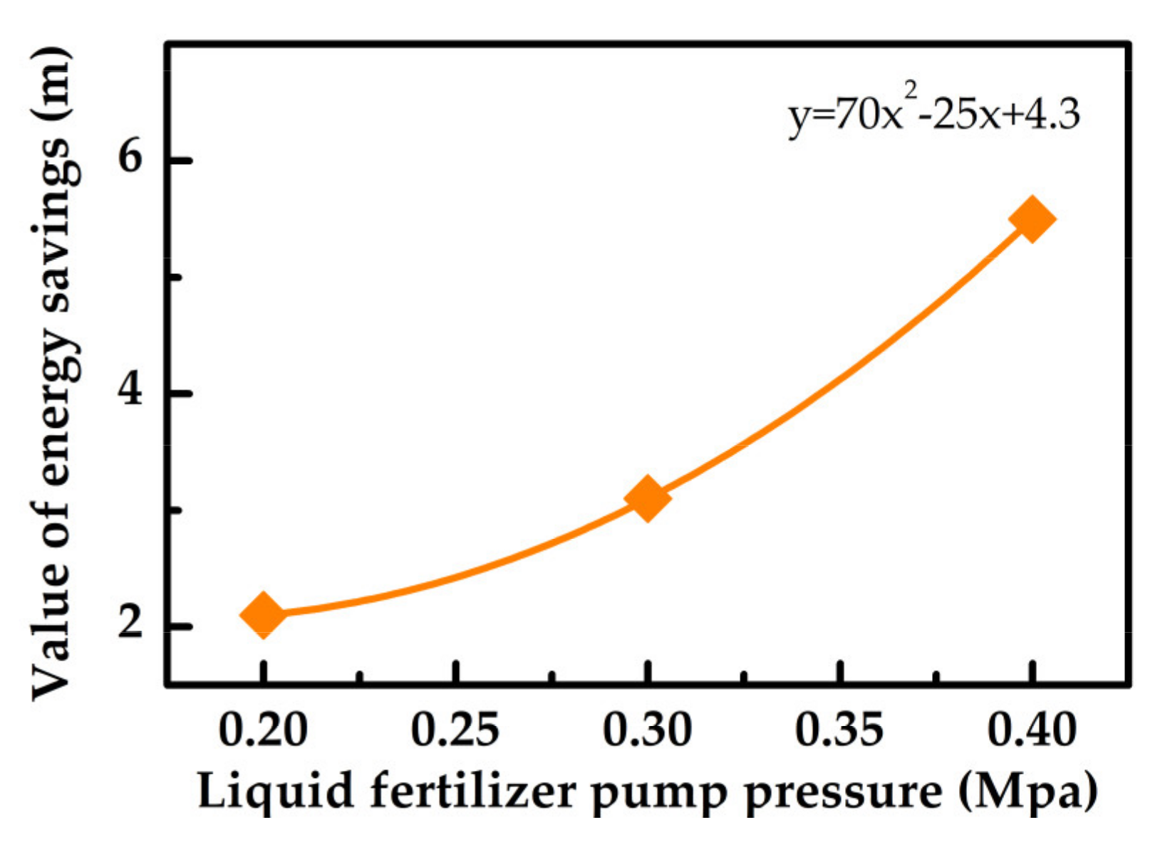
2.8.2. Fertilizer Energy Loss and Liquid Fertilizer Pump Pressure Bench Test

To explore the relationship between energy loss and liquid fertilizer pump pressure, the head loss of the differential two-way fertilizer supply distribution device was calculated by Bernoulli equation, as shown in Equation (1).
Z 1 + P 1 ρ g + v 1 2 2 g = Z 2 + P 2 ρ g + v 2 2 2 g + h w
where, Z1 is the position head (m), P1 is the Static pressure of liquid fertilizer at the outlet of liquid fertilizer pump (Pa), P2 is the Static pressure of liquid fertilizer at the outlet of fertilizer spray needle (Pa), ρ is the liquid fertilizer density (kg m−3), g is the gravitational acceleration (m s−2), v1 is the liquid fertilizer flow velocity at the outlet of the liquid fertilizer pump (m s−1), v2 is the liquid fertilizer flow velocity at the outlet of the fertilizer spray needle (m s−1), hw is the total head loss of liquid fertilizer (m).
According to the volume of liquid fertilizer and injecting time according to Equation (2) to calculate the flow of the fertilizer spray needle at the outlet at different pressures.
v 2 = V A 2 t
where, v2 is the fertilizer spray needle outlet flow velocity (m s−1), A2 is the cross-sectional area at the outlet of a single fertilizer spray needle (m2), V is the liquid fertilizer volume, (m3), t is the fertilizer injecting time, (s).
The flow velocity at the outlet of the liquid fertilizer pump is calculated by the continuity equation of the fluid, i.e., Equation (3).
v 1 A 1 = 4   v 2 A 2
where, A1 is the cross-sectional area at the liquid fertilizer pump outlet, (m2), since Z1Z2 is approximately equal to 1.0 m, so α = 1, the flow of liquid fertilizer at the outlet of the fertilizer spray needle is free outflow, so P2P1 = 0. According to Equation (3), the entire pipeline system can be obtained with the total head loss of liquid fertilizer pressure changes.

2.9. Field Test

To verify the working performance of the fertilizer application machine, a field test was conducted. The test was conducted on 18 June 2020 in the experimental field (127°2′58″ S, 45°31′18″ E) of Northeast Agricultural University in Acheng District, Harbin (Heilongjiang Province). The climate is temperate monsoon, with an annual precipitation of 500–600 mm, an average annual temperature of 4.25 °C, short cool summers, and long cold winters. The experimental area was 130 m × 50 m, and the study area was the Dongnong No. 253 corn field, which was in the intertillage and fertilization period. The pre-sowing period met the requirements of the dominant planting pattern of 650 mm row spacing and 300–320 mm plant spacing. The mean values of the main physical and chemical properties of the soil are shown in Table 2, where the cone index was determined by a TJSD-750 soil firmness tester (Baoding, Hebei, China Puyunong Technology Co., Ltd.). Soil bulk density was measured by the ring knife method, using an aluminum ring knife (60 cm3) and an electronic balance (accuracy 0.01 g, Shenzhen, Guangdong, China Lintao Instruments Co.). Soil water content and temperature were measured by a VMS-3000-TR soil temperature and water content sensor (Jinan, Shandong, China Vemsee Corporation). Soil cone index was determined by a TJSD-750 soil firmness tester (Baoding, Hebei, China Puyunong Technology Co., Ltd.), and pH was determined by a ZD-06 soil acidity moisture meter (Shenzhen, Guangdong, China Zhengda Instrument Co., Ltd.).

2.10. Test Program

In this study, the width of the holes and the spacing of the holes was used as an indicator to measure the performance of the liquid fertilizer hole application machine. The experimental fields were calibrated according to the number of rows, and each row was randomly selected to measure the width of the holes and the spacing between the holes with 100 holes. A steel plate ruler was used to measure the width of the holes; a stopwatch was used to calibrate the working speed and rotation speed of the drilling during the field operation of the hole applicator. The test factors were coded as shown in Table 3.
ANOVA was used to analyze the variance values of the test data and determine whether the factors had a significant effect on the test indexes and whether the interaction was significant. The response surface was fitted with a binary regression equation to determine the optimal combination of hole rotation speed and forward velocity to achieve the theoretically optimal hole width and spacing response index values.

3. Results and Discussion

3.1. Fertilizer Application Volume and Liquid Fertilizer Pump Pressure Bench Test

The results of the single-factor test for the fertilizer spray performance test are shown in Table 4.
It can be seen from Figure 11 that when the rotational speed of the distribution device is fixed at 75 r min−1, the amount of fertilizer applied increases with the increase of liquid fertilizer pump pressure. The reason is that when the rotational speed and injecting time of the differential two-way fertilizer distribution device are certain, the volume of the fertilizer applied is proportional to the cross-sectional area of the fertilizer inject port and the flow velocity. Under the condition that the cross-sectional area of the fertilizer spray port is certain, the volume of the fertilizer is only related to the flow velocity, while the flow velocity is proportional to the pressure of the liquid fertilizer pump, so the fertilizer application volume gradually increases with the increase of the pressure of the liquid fertilizer pump. For fertilizer spray performance, it is important to be able to maintain a linear variation of the pressure of the liquid fertilizer pump with respect to the amount of fertilizer applied. These results were consistent with a finding proposed by Da Silva and Maglhães [33], and Fuadi et al. [34].

3.2. Energy Saving Test

The data on the volume and timing of fertilizer injecting in the energy saving experiment are shown in Table 5.
According to the sum of volume and time of liquid fertilizer in Table 5. According to Equation (2), the flow velocity of liquid fertilizer at different pressures at the outlet of the fertilizer spray needle was calculated, and the values of 8.7, 10.4, and 12.1 m s−1.
The flow velocity at the outlet of the liquid fertilizer pump is calculated by Equation (3), where the cross-sectional diameter at the outlet of the liquid fertilizer pump is 11 mm, and its values are 1.8, 2.1, and 2.5 m s−1. The total head loss of liquid fertilizer with pressure for the entire piping system had values of 9.0, 12.6, and 15.0 m. The total head loss values of the liquid-fertilizer rotor-type converter were calculated to be 11.1, 15.7, and 20.5 m. The calculated energy saving values of the piping system for the differential two-way fertilizer supply distribution device are 2.1, 3.1, and 5.5 m. The relationship between energy saving and liquid fertilizer pump pressure is obtained, as shown in Figure 12.
The energy loss of liquid fertilizer in the differential two-way fertilizer supply distribution device is caused by local head loss and line loss, the length of the fertilizer delivery pipe of the whole device is short, and the resistance coefficient along the pipe wall material is small. Therefore, this study ignores the line loss. The head loss is expressed by hj. Equation (4) can analyze the mechanism of local head loss in the flow of liquid fertilizer in the pipeline. According to the head loss values in Figure 12, it is known that the liquid fertilizer energy loss gradually increases with the gradual increase of liquid fertilizer pump pressure.
The piping system of differential bidirectional fertilizer supply and distribution device has four fertilizer injecting needles, two more than the liquid fertilizer rotor type converter [32]. Based on the fluid continuity equation, the liquid fertilizer flow velocity at the outlet of the differential two-way fertilizer supply distribution device is equal to half of that of the liquid fertilizer rotor type converter, and its local resistance loss includes one sudden expansion tube, two sudden reduction tubes, and one 90° right-angle round bend tube, with local loss coefficients of 0.23, 0.34, and 0.8, respectively. Although the differential two-way fertilizer supply distribution device had one more 90° right angle round bend tube loss form compared with the liquid fertilizer rotor type converter, the theoretical analysis of the distribution device liquid fertilizer energy loss is less than the converter liquid fertilizer energy loss, the formula for the Equations (5) and (6). The test results show that the differential two-way fertilizer supply distribution device has higher fertilizer spraying efficiency.
H j = ζ v 2 2 g
where, v is the average flow velocity of cross section (m s−1), g is the gravitational acceleration (m s2), ζ is the local resistance coefficient.
H 1 j = 0.34   v 2 2 g
h 2 j = 0.57   v 2 2 g
where, h1j is the differential two-way fertilizer supply distribution device energy loss (J), h2j is the energy loss of liquid fertilizer rotor type converter (J).

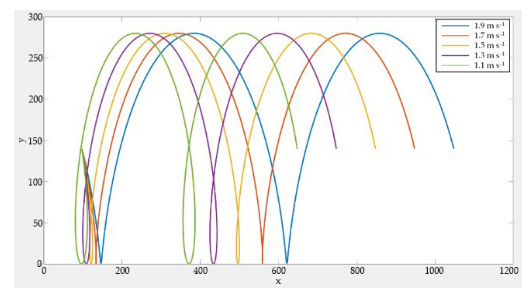
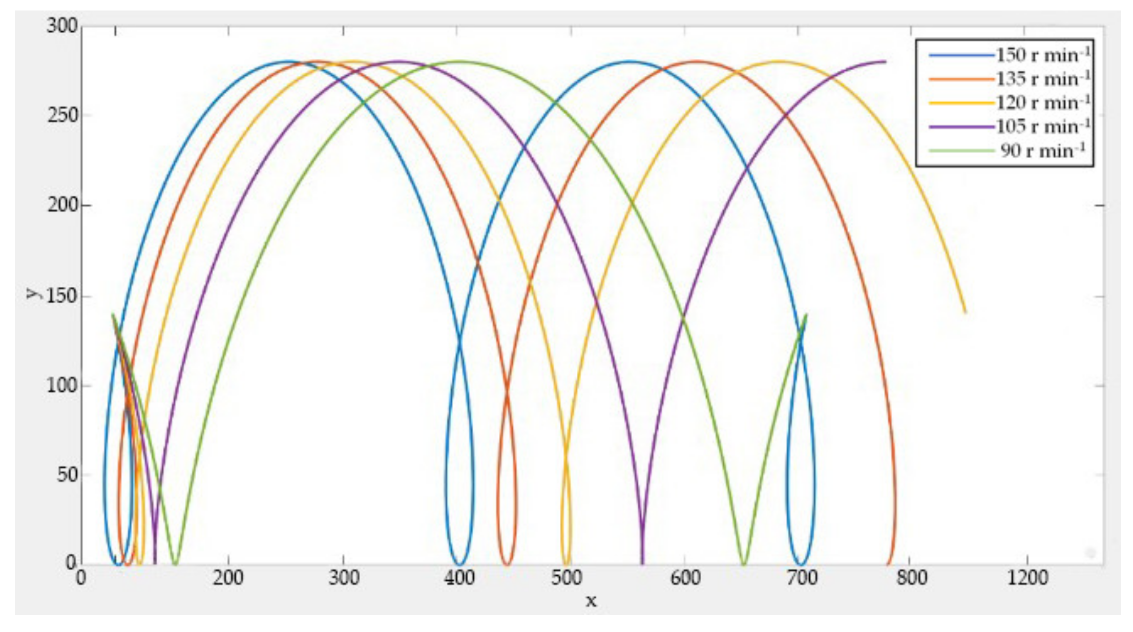
3.3. Effect of Forward Speed and Drilling Speed on Hole Width and Hole Spacing

To investigate the effect of forward speed and drilling speed on hole width and hole spacing, the machine was tested in the field at different forward speeds. The fertilizer needle drilling motion combines two motions [35,36]: one is a circular motion when the drilling mechanism rotates, and the other is a linear motion when the machine keeps moving. When the trajectory of the fertilizer injection needle is a “short pendulum”, the hole width is the distance between the in-soil and out-soil points of the needle body. When the trajectory of the fertilizer injection needle is a “trochoid”, the hole width is the maximum chord length of the trajectory of the needle body into and out of the soil [36]. Figure 13 shows the drilling trajectory of the fertilizer injecting needle under the action of forward speed of 1.1–1.9 m s−1, when the drilling speed is 120 r min−1. As the forward speed increases, the hole width first decreases and then increases, and the hole spacing gradually increases. Figure 14 shows the drilling trajectory of the fertilizer injecting needle under the action of 90–150 r min−1, when the forward speed is 1.5 m s−1. As the drilling speed increases, the hole width decreases and then increases, and the hole spacing gradually decreases.

3.4. Parameter Optimization Test Results

The effective cooperation between the drilling speed and forward speed is the key factor for the small hole opening of soil surface travel. To obtain the change pattern of the hole width and hole spacing under the interaction of different advancing speeds and drilling speeds of the machine, the experiments were conducted with the forward speed and the drilling speed as the independent variables, and the hole width and hole spacing as the measurement indicators, using a quadratic orthogonal rotational combination design test [37,38] scheme to obtain the variation law of the hole width and hole spacing under the interactions of different forward speeds and drilling speeds of the implement; the obtained test results are shown in Table 6.

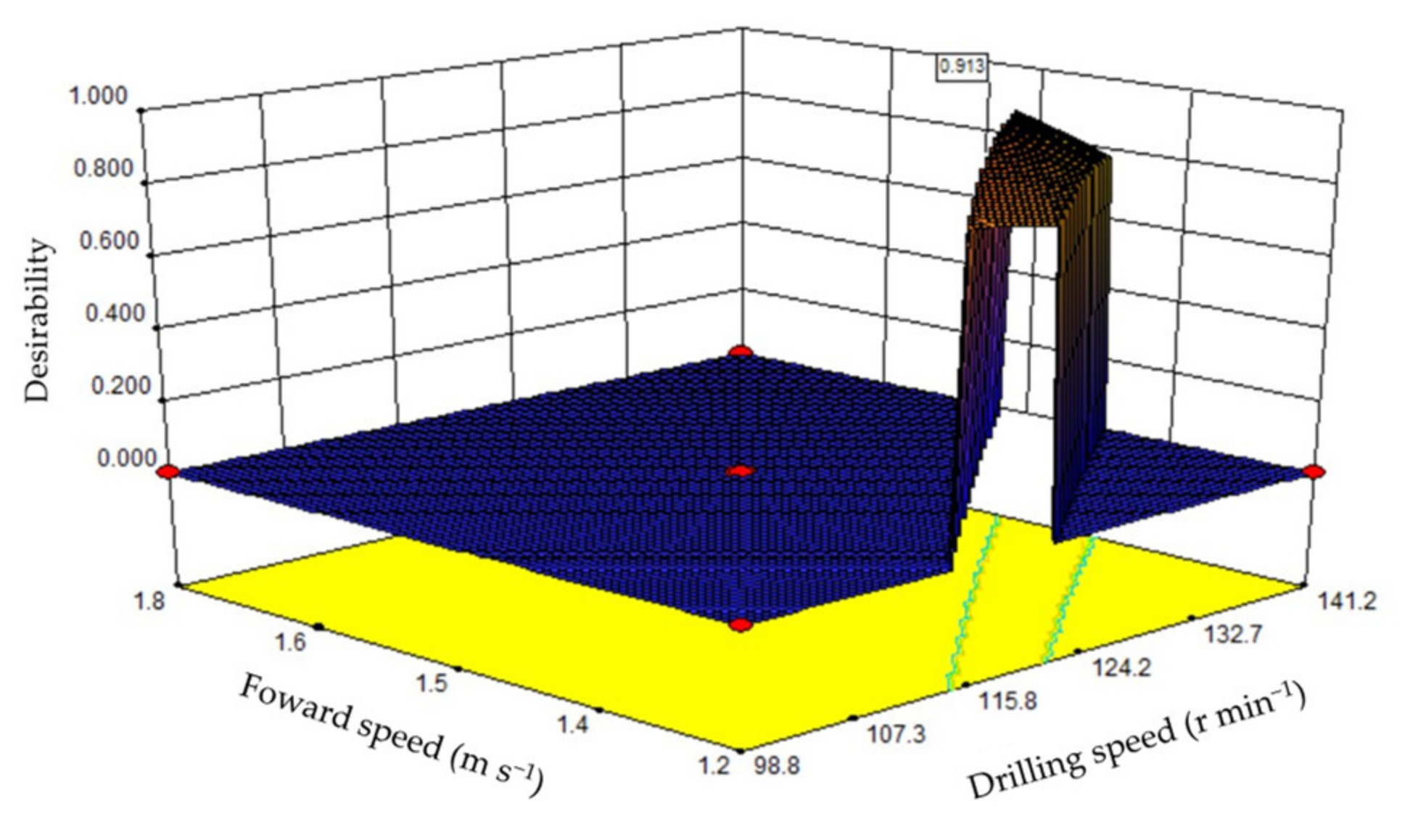
3.5. Response Surface Analysis

We can see that the interaction between the drilling speed and forward velocity is significant. These results were consistent with a finding proposed by Hu, Li, Wang, He, Zhang, Chen and Wang [4], Gaowei et al. [39]. Finally, the test data were optimized to obtain an optimal range of operating parameters. The constraint conditions were Y1 = min, Y2 = 300–320 mm, X1 = 90–150 mm and X2 = 1.1–1.9 m s−1, as shown in Figure 15. When the working speed and advance speeds were 127 r min−1 and 1.40 m s−1, respectively, the performance of the drilling mechanism was optimal, with a hole width of 39.9 mm and a hole spacing of 320 mm.
The interaction between the drilling mechanism speed and the forward speed of the machine is satisfied by the different trajectories formed by the fertilizer injecting needles, with consequent differences in the width of the holes on the soil surface. To achieve a small hole opening and agronomically required hole spacing, tests were carried out with different operating parameters. The results showed that when the working speed and forward speeds were 127 r min−1 and 1.40 m s−1, respectively, the performance of the machine was optimal, and a better fertilizer delivery method could be achieved for corn plants.

4. Conclusions

In this study, we proposed an efficient liquid fertilizer drilling method based on alternate drilling, and found that the forward speed and drilling speed had a significant effect on the hole width and hole spacing. The optimal combination of parameters for the most suitable corn growing area was 127 r min−1 and 1.40 m s−1 for drilling speed and forward speed. The hole width is 39.9 mm and the hole spacing is 320 mm.
The results of this paper show that an efficient liquid fertilizer drilling method based on alternate drilling can effectively reduce the hole width to minimize liquid fertilizer volatilization compared with the traditional liquid fertilizer deep application method and is suitable for the spacing of maize crops. Therefore, this method can provide an effective means for the future field of agricultural machine design. At the same time, this operation method can significantly reduce the amount of chemical fertilizer application, reduce environmental pollution, and bring greater economic benefits.
The results of this paper also have some limitations. First, the results of this paper are mainly applicable to maize crops, while the applicability to other crops needs to be further investigated. Second, the field trials conducted in this study included a few uncontrolled variables, so the results of this paper may not be able to better illustrate the regularity of the test results, and a large number of replicated trials in soil bins should be conducted to further verify the effectiveness of the machine operation.

Author Contributions

Conceptualization, W.Z. and J.W. (Jinwu Wang); methodology, Z.L.; software, N.W.; validation, J.W. (Jinfeng Wang); formal analysis, H.T.; investigation, Q.W.; writing—original draft preparation, N.W.; writing—review and editing, W.Z. All authors have read and agreed to the published version of the manuscript.

Funding

This work was funded by the National Natural Science Foundation of China (Grant Nos. 51905086, 51675093), China Postdoctoral Science Foundation Funded Project (Grant No. 2019M66124), Heilongjiang Postdoctoral Science Foundation Specially Funded Project (Grant No. LBH-Z19044), and Heilongjiang Province General Undergraduate Higher Education Institution Young Innovative Talents Training Program (UNPYSCT-2020100).

Institutional Review Board Statement

Not applicable.

Data Availability Statement

Not applicable.

Acknowledgments

The authors would like to thank their schools and colleges, as well as the funding providers of the project. All support and assistance are sincerely appreciated.

Conflicts of Interest

The authors declare that there is no conflict of interest.

References

  1. Hong, H.; Zhang, Y.; Chen, W.; Zhao, H. Present research situation and perspective of corn topdressing machinery in China. J. Maize Sci. 2016, 24, 147–152. [Google Scholar]
  2. Zeng, X.; Peng, Z.; Peng, Y. Structural equation model analyzing relationship among N application-carbonhydrate product-grain yield of maize. Trans. Chin. Soc. Agric. Eng. 2016, 32, 98–104. [Google Scholar]
  3. Zhan, L.; Yang, H.; Lei, H. Analysis of corn water consumption, carbon assimilation and ecosystem water use efficiency based on flux observations. Trans. Chin. Soc. Agric. Eng. 2016, 32, 88–93. [Google Scholar]
  4. Hu, H.; Li, H.; Wang, Q.; He, J.; Zhang, Y.; Chen, W.; Wang, X. Design and experiment of targeted hole-pricking and deep-application fertilizer applicator between corn rows. Trans. Chin. Soc. Agric. Eng. 2016, 32, 26–35. [Google Scholar]
  5. de Castro, S.G.Q.; Decaro, S.T.; Franco, H.C.J.; Graziano Magalhães, P.S.; Garside, A.; Mutton, M.A. Best practices of nitrogen fertilization management for sugarcane under green cane trash blanket in Brazil. Sugar Tech 2017, 19, 51–56. [Google Scholar] [CrossRef]
  6. Zou, H.; Fan, J.; Zhang, F.; Xiang, Y.; Wu, L.; Yan, S. Optimization of drip irrigation and fertilization regimes for high grain yield, crop water productivity and economic benefits of spring maize in Northwest China. Agric. Water Manag. 2020, 230, 105986. [Google Scholar] [CrossRef]
  7. Çetin, Ö.; Akalp, E. Efficient use of water and fertilizers in irrigated agriculture: Drip irrigation and fertigation. Acta Hortic. Et Regiotect. 2019, 22, 97–102. [Google Scholar] [CrossRef] [Green Version]
  8. Nandede, B.; Raheman, H.; Deore, H. Selection of suitable furrow opener and furrow closer for vegetable transplanter. Agric. Mech. Asia Afr. Lat. Am. 2014, 45, 40–47. [Google Scholar]
  9. Rahman, S.; Chen, Y.; Lobb, D. Soil movement resulting from sweep type liquid manure injection tools. Biosyst. Eng. 2005, 91, 379–392. [Google Scholar] [CrossRef]
  10. Guo, Y.; Liu, J.; Yin, H.; Zhang, Q.; Li, L.; Wang, Y. Effects of quantitative fertilization by a single plant on the yield, nutrient absorption, and utilization of summer maize. J. Agric. Resour. Environ. 2020, 37, 924–930. [Google Scholar]
  11. Zheng, Z.; Wang, T.; Liu, Z.; Wang, Q.; Zhao, H.; Liu, S. STUDY ON FILLING PERFORMANCE OF HOLE FERTILIZATION DEVICE AND OPTIMIZATION OF CAVITY. INMATEH-Agric. Eng. 2021, 64, 141–150. [Google Scholar] [CrossRef]
  12. Ulson, J.A.C.; Benez, S.H.; da Silva, I.N.; de Souza, A.N. An Intelligent System to Control the Fluid Fertilizer Application. In Proceedings of the 2002 ASAE Annual Meeting, Chicago, IL, USA, 28–31 July 2002; p. 1. [Google Scholar]
  13. O’Shaughnessy, S.A.; Evett, S.R.; Colaizzi, P.D. Dynamic prescription maps for site-specific variable rate irrigation of cotton. Agric. Water Manag. 2015, 159, 123–138. [Google Scholar] [CrossRef]
  14. Goldstein, A.; Fink, L.; Meitin, A.; Bohadana, S.; Lutenberg, O.; Ravid, G. Applying machine learning on sensor data for irrigation recommendations: Revealing the agronomist’s tacit knowledge. Precis. Agric. 2018, 19, 421–444. [Google Scholar] [CrossRef]
  15. Bianchini, A.; Valadão Junior, D.D.; Rosa, R.P.; Colhado, F.; Daros, R.F. Soil chiseling and fertilizer location in sugarcane ratoon cultivation. Eng. Agrícola 2014, 34, 57–65. [Google Scholar] [CrossRef] [Green Version]
  16. Otto, R.; Franco, H.C.J.; Faroni, C.E.; Vitti, A.C.; de Oliveira, E.C.A.; Sermarini, R.A.; Trivelin, P.C.O. The role of nitrogen fertilizers in sugarcane root biomass under field conditions. Agric. Sci. 2014, 5, 1527. [Google Scholar] [CrossRef] [Green Version]
  17. Karagöz, İ. Fertilization and Fertilizer Types. Appl. Soil Chem. 2021, 123–148. [Google Scholar] [CrossRef]
  18. Shahena, S.; Rajan, M.; Chandran, V.; Mathew, L. Conventional methods of fertilizer release. In Controlled Release Fertilizers for Sustainable Agriculture; Elsevier: Amsterdam, The Netherlands, 2021; pp. 1–24. [Google Scholar]
  19. Womac, A.; Tompkins, F. Probe-type injector for fluid fertilizers. Appl. Eng. Agric. 1990, 6, 149–154. [Google Scholar] [CrossRef]
  20. da Silva, M.J.; Franco, H.C.J.; Magalhães, P.S.G. Liquid fertilizer application to ratoon cane using a soil punching method. Soil Tillage Res. 2017, 165, 279–285. [Google Scholar] [CrossRef]
  21. Wang, J.; Ji, W.; Feng, J. Design and experimental investigation of the liquid fertilizer applicator. Trans. Chin. Soc. Agric. Eng. 2008, 24, 157–159. [Google Scholar]
  22. Wang, J.; Pan, Z.; Zhou, W.; Wang, J.; He, J.; Lang, C.; University, N.A. Design and Test of SYJ-2 Type Liquid Variable Fertilizer. Trans. Chin. Soc. Agric. Mach. 2015, 46, 53–58. [Google Scholar]
  23. Wang, J.; Liu, Y.; Wang, J.; He, J. Optimization design and experiment of liquid-fertilizer applying deep-fertilization mechanism for planetary elliptic gears. Trans. Chin. Soc. Agric. Mach. 2012, 43, 60–65. [Google Scholar]
  24. Yu, Y.; Luo, C.; Yu, G.; Zhao, X.; Yu, T. Parameters optimization of pick-up mechanism of planetary gear train with ellipse gears and incomplete non-circular gear. Trans. Chin. Soc. Agric. Mach. 2013, 44, 62–68. [Google Scholar]
  25. Chen, J.; Huang, Q.; Wang, Y.; Zhang, G. Kinematics modeling and analysis of transplanting mechanism with planetary elliptic gears for pot seedling transplanter. Trans. Chin. Soc. Agric. Eng. 2012, 28, 6–12. [Google Scholar]
  26. Jagannath, R.; Naresh, N.; Pandey, K. Studies on pressure loss in sudden expansion in flow through nozzles: A fuzzy logic approach. ARPN J. Eng. Appl. Sci. 2007, 2, 50–61. [Google Scholar]
  27. Tassone, A.; Caruso, G.; Del Nevo, A. Influence of PbLi hydraulic path and integration layout on MHD pressure losses. Fusion Eng. Des. 2020, 155, 111517. [Google Scholar] [CrossRef]
  28. Quaglia, G.; Nisi, M. Design of a self-leveling cam mechanism for a stair climbing wheelchair. Mech. Mach. Theory 2017, 112, 84–104. [Google Scholar] [CrossRef]
  29. Zhou, C.; Hu, B.; Chen, S.; Ma, L. Design and analysis of high-speed cam mechanism using Fourier series. Mech. Mach. Theory 2016, 104, 118–129. [Google Scholar] [CrossRef] [Green Version]
  30. Ouyang, T.; Wang, P.; Huang, H.; Zhang, N.; Chen, N. Mathematical modeling and optimization of cam mechanism in delivery system of an offset press. Mech. Mach. Theory 2017, 110, 100–114. [Google Scholar] [CrossRef]
  31. Wang, J.; Zhou, W.; Bai, H.; Wang, J.; Huang, H.; Wang, Z. Design and experiment of differential-type bidirectional distribution device for fertilizer supply for deep-fertilizer liquid fertilizer application. Trans. Chin. Soc. Agric. Mach. 2018, 49, 105–111. [Google Scholar]
  32. Wang, J.; Pan, Z.; Yang, X.; Liu, Y.; Zhang, C.; Wang, J. Design and experiment of rotary converter of liquid fertilizer. Trans. Chin. Soc. Agric. Mach. 2014, 45, 110–165. [Google Scholar]
  33. Da Silva, M.; Magalhães, P. Modeling and design of an injection dosing system for site-specific management using liquid fertilizer. Precis. Agric. 2019, 20, 649–662. [Google Scholar] [CrossRef]
  34. Fuadi, M.; Sutiarso, L.; Virgawati, S.; Nugraheni, P. Design of liquid fertilizer applicator based on Variable Rate Application (VRA) for Soybean. In Proceedings of the IOP Conference Series: Earth and Environmental Science, Moscow, Russia, 27 May–6 June 2019; p. 012009. [Google Scholar]
  35. Chen, J.; Huang, Q.; Wang, Y.; Sun, L.; Zhao, X.; Wu, C. Parametric analysis and inversion of transplanting mechanism with planetary non-circular gears for potted-seedling transplanter. Trans. Chin. Soc. Agric. Eng. 2013, 29, 18–26. [Google Scholar]
  36. Zhao, X.; Chen, J.; Wang, Y.; Zhao, Y.; Li, C. Reverse design and analysis of rice seedling transplanter with D-shape static trajectory. Trans. Chin. Soc. Agric. Eng. 2012, 28, 92–97. [Google Scholar]
  37. Wu, R.; Zhang, L.; Qian, F.; Cai, H. Design and simulation of cave-fertilizer apparatus for maize. J. Anhui Agric. Univ. 2017, 44, 941–946. [Google Scholar]
  38. Hoshyarmanesh, H.; Dastgerdi, H.R.; Ghodsi, M.; Khandan, R.; Zareinia, K. Numerical and experimental vibration analysis of olive tree for optimal mechanized harvesting efficiency and productivity. Comput. Electron. Agric. 2017, 132, 34–48. [Google Scholar] [CrossRef]
  39. Xu, G.; Jian, S.; Song, Y.; Fang, H.; Qiu, X.; Ming, X. Design and Experiment of Cellular Cavitation Mechanism for Crops of Hilly Mountains Transplante. Trans. Chin. Soc. Agric. Mach. 2022, 53, 105–113, 125. [Google Scholar]
Figure 1. The deep-hole liquid fertilizer applicator. (a) side view. (b) rear view. (c) top view. 1. frame assembly; 2. liquid fertilizer injecting control mechanism; 3. liquid fertilizer feeding main pipeline; 4. sprocket A; 5. main drive shaft; 6. liquid fertilizer pump; 7. three-point suspension assembly; 8. worm gear reducer; 9. power input shaft assembly; 10. helical spur gear binding mechanism; 11. liquid fertilizer feeding branch rod; 12. ground wheel assembly; 13. main drive belt; 14. sprocket B; 15. sprocket C; 16. sprocket D.
Processes 10 01320 g001
Figure 2. Photo of the deep-hole liquid fertilizer applicator.
Processes 10 01320 g002
Figure 3. Drilling mechanism. (a) two-dimensional diagram of the structure. (b) two-dimensional diagram of spur gear planetary systems. (c) diagram of field work. 1. sprocket shaft; 2. helical gear; 3. Flange; 4. outer casing; 5. planetary frame; 6. rocker arm; 7. fertilizer spray needle; 8. upper planetary wheel; 9. intermediate wheel; 10. lower planetary wheel.
Processes 10 01320 g003
Figure 4. Sketch of full spur gear planetary mechanism.
Processes 10 01320 g004
Figure 5. Two-dimensional model of the liquid fertilizer injecting control mechanism. (a) Liquid fertilizer injecting control mechanism; (b) differential wheel mechanisms; (c) cylindrical hollow cam mechanism. 1. sprocket shaft housing; 2. outer housing; 3. inner gear ring; 4. planetary wheel; 5. sprocket shaft; 6. main shaft sleeve; 7. sub shaft sleeve; 8. top bar; 9. cylindrical hollow cams. 10. running pulley.
Processes 10 01320 g005
Figure 6. Hose connection type.
Processes 10 01320 g006
Figure 7. Differential wheel mechanism 3D model. 1. Planetary wheel; 2. Inner gear ring; 3. Sprocket shaft.
Processes 10 01320 g007
Figure 8. Two-dimensional diagram of fertilizer needles in the soil and out of the soil.
Processes 10 01320 g008
Figure 9. Cylindrical hollow cam mechanism 3D model.1. Roller; 2. Top bar; 3. Cylindrical hollow cam.
Processes 10 01320 g009
Figure 10. Test device. 1. Liquid fertilizer pump; 2. Distribution device; 3. Cavity tying mechanism; 4. Funnel; 5. Measuring cylinder; 6. Syringe; 7. Fertilizer injecting needle; 8. Fertilizer measuring container.
Processes 10 01320 g010
Figure 11. Influence of different hydraulic pump pressures on liquid fertilizer amount.
Processes 10 01320 g011
Figure 12. Relationship between energy saving and liquid fertilizer pump pressure.
Processes 10 01320 g012
Figure 13. Relationship between the influence of the forward speed on trajectory.
Processes 10 01320 g013
Figure 14. Relationship between the influence of the drilling speed on the trajectory.
Processes 10 01320 g014
Figure 15. Optimization of optimal operating parameter range.
Processes 10 01320 g015
Table 1. The main equipment used for the test.
NameSpecificationsFunction
Fertilizer measuring
container
1500 mLObtain fertilizer from the fertilizer spray needle
FunnelD-100 mmPreventing fertilizer from overflowing from the measuring cylinder when measuring
Syringes30 mLAccurate acquisition of the residual fertilizer in the fertilizer measuring container
StopwatchPrecision-0.01 sMeasurement of fertilizer injecting time
Measuring cylinder200 mLMeasuring the volume of fertilizer
Liquid fertilizerUrea ammonium nitrate solution (1%)Test drug
Table 2. Physical and chemical properties of soil in the Acheng experimental field base of Northeast Agricultural University.
Cone Index
(MPa)
Soil Bulk Density
(g cm−3)
Soil Water Content
(%)
Soil
Temperature
(°C)
Depth
(mm)
pH
0.81.2913.5025.47807.14
Table 3. Coding table of level of experimental factors.
Code NumberDrilling Speed
(r min−1)
Forward Speed
(m s−1)
+1.414150.01.9
+1141.21.8
0120.01.5
−198.81.2
−1.41490.01.1
Table 4. Liquid fertilizer volume and time data.
Liquid Fertilizer Pump Pressure
(Mpa)
Amount of Fertilizer
(mL)
FirstSecondThirdFourthFifth
0.213.813.714.113.613.6
0.319.619.419.219.019.2
0.422.422.722.121.922.7
Table 5. New pipeline system liquid fertilizer volume and time data.
No.Pressure (MPa)
0.20.30.4
Volume
(mL)
Time
(s)
Volume
(mL)
Time
(s)
Volume
(mL)
Time
(s)
First852.74.961040.44.911207.05.05
Second846.45.001025.74.961204.15.12
Third851.65.111021.55.021198.35.10
Fourth856.84.911018.45.041197.54.96
Fifth850.75.011021.85.021203.65.02
Total4258.224.995127.824.956010.525.25
Table 6. Schemes and results of experiment.
NoTest FactorsPerformance Indicator
X1-Drilling Speed
(r min−1)
X2-Forward Speed
(m s−1)
Y1-Hole Width
(mm)
Y2-Hole Spacing
(mm)
1−1−139.6363.7
21−166.6255.4
3−1199.7544.4
41140.9383.3
5−1.414083.2499.7
61.414054.1300.9
70−1.41460.9274.2
801.41474.5475.0
90038.2375.0
100041.3372.1
110036.1376.0
120038.6379.0
130035.1371.2
140033.3376.3
150035.3372.6
Publisher’s Note: MDPI stays neutral with regard to jurisdictional claims in published maps and institutional affiliations.

