
A Magnetic Field Canceling System Design for Diminishing Electromagnetic Interference to Avoid Environmental Hazard


Abstract
:1. Introduction
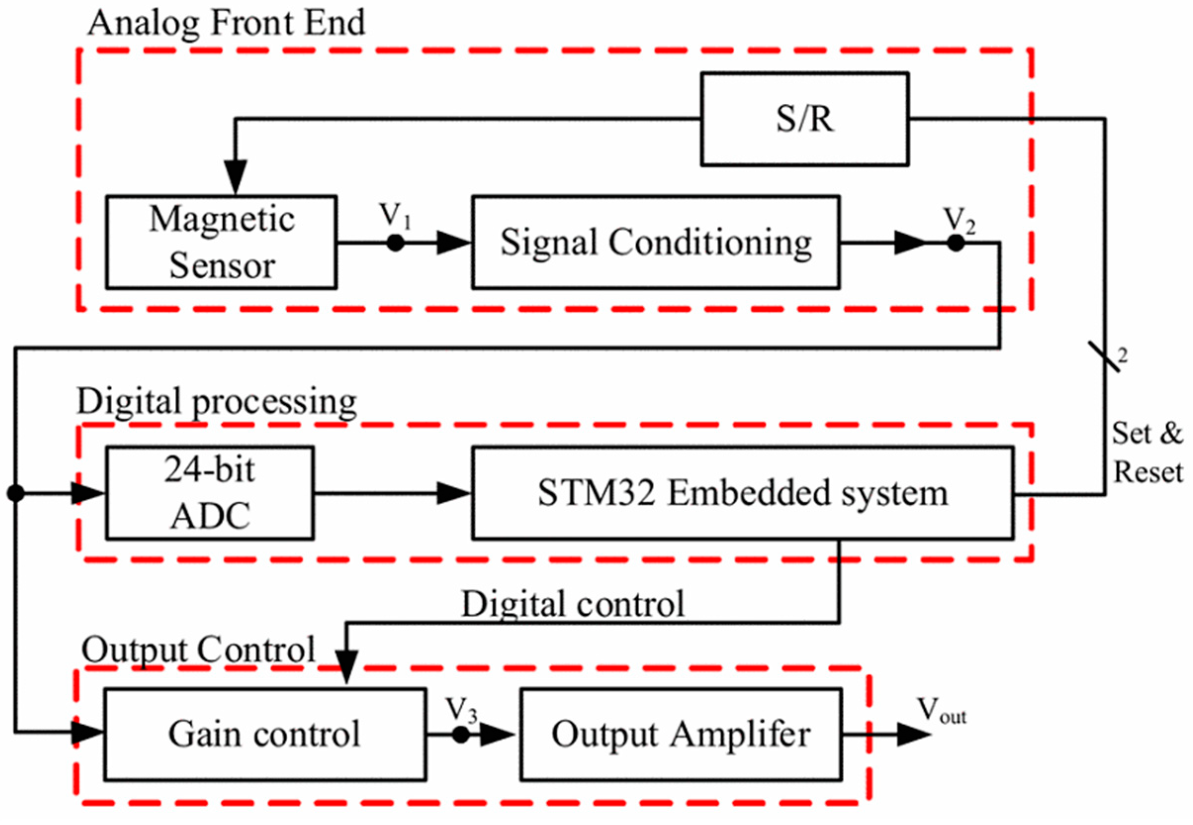
2. System Design
2.1. System Requirements
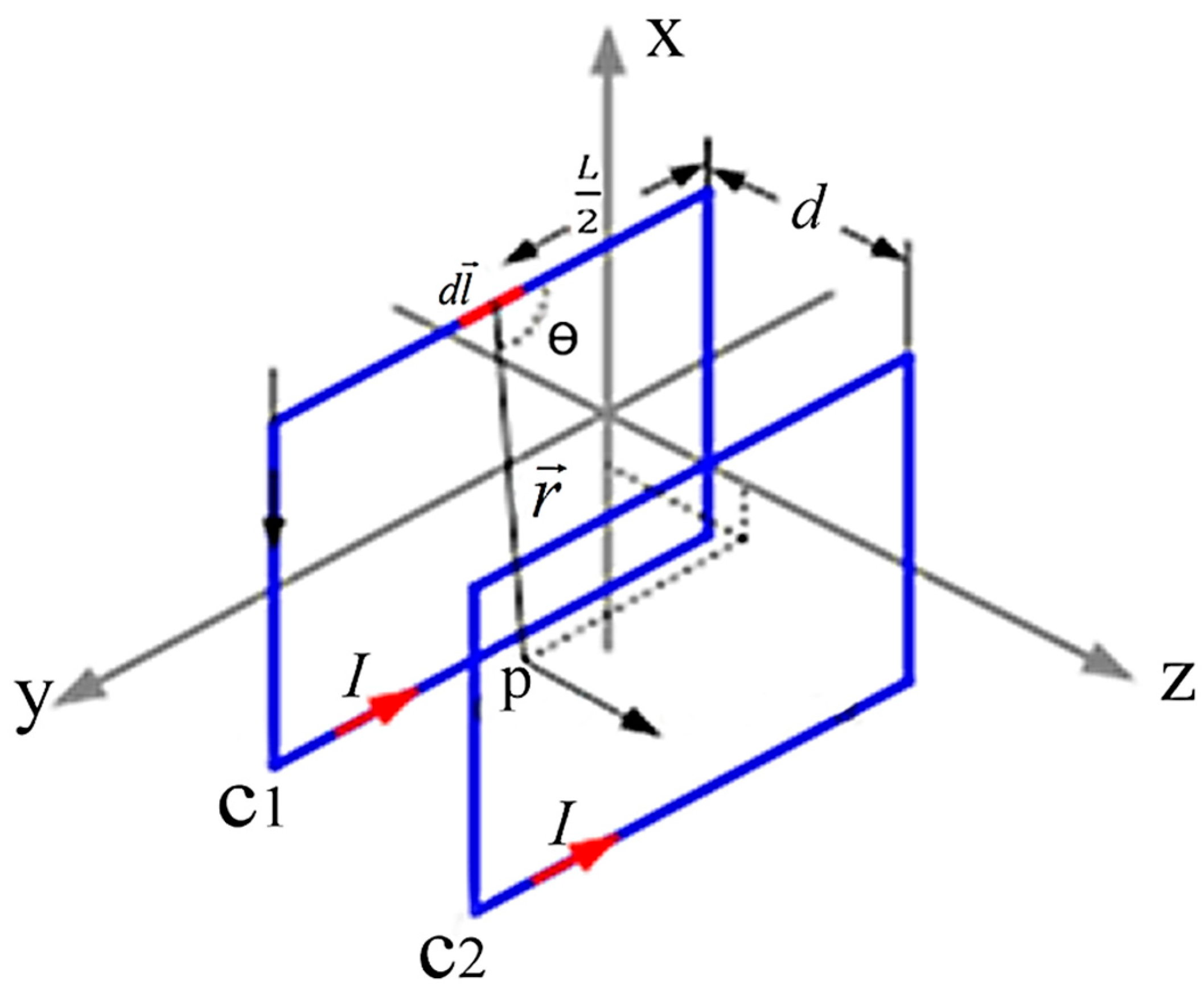
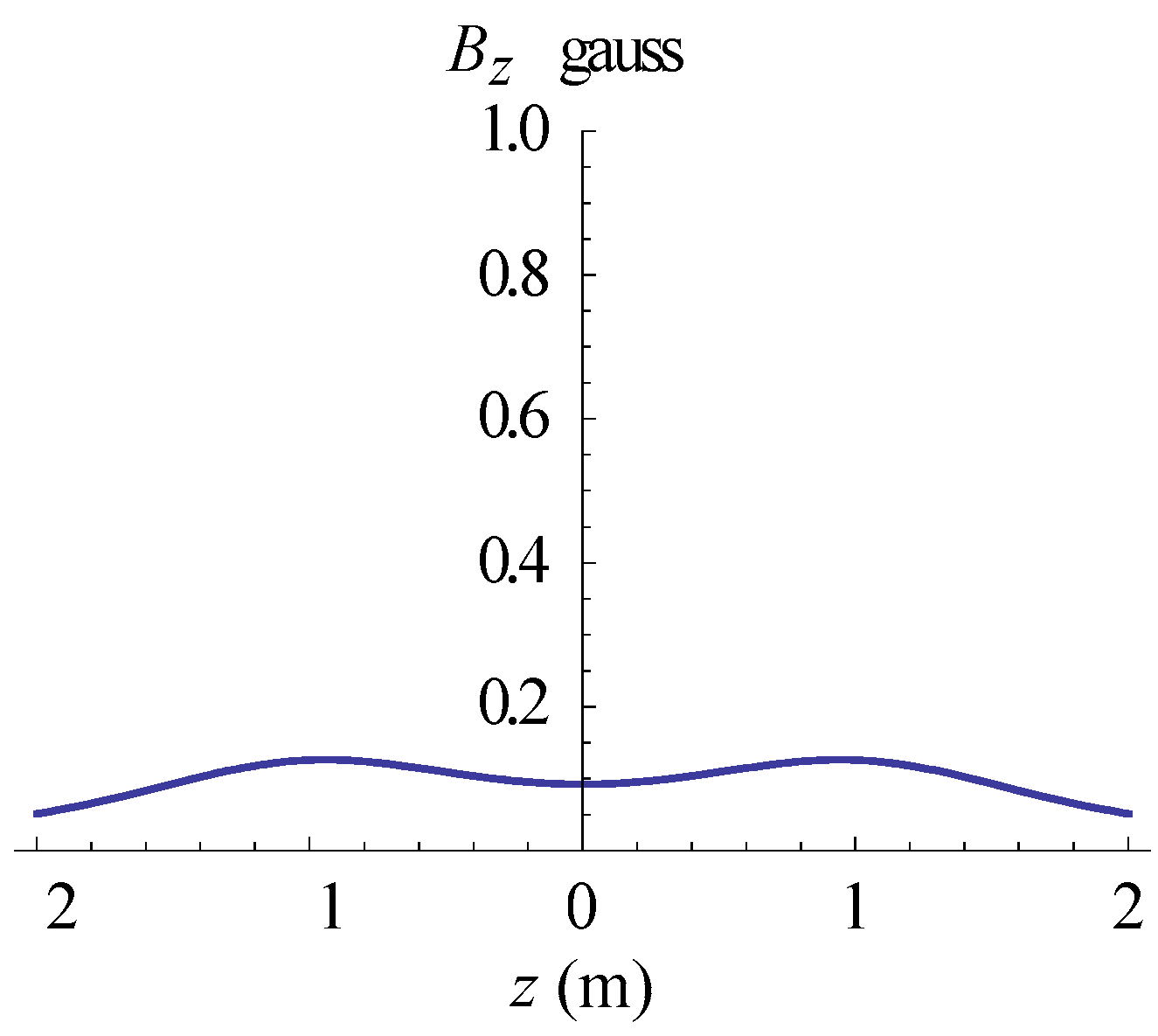
2.2. Mathematical Model of a Square Helmholtz Coil
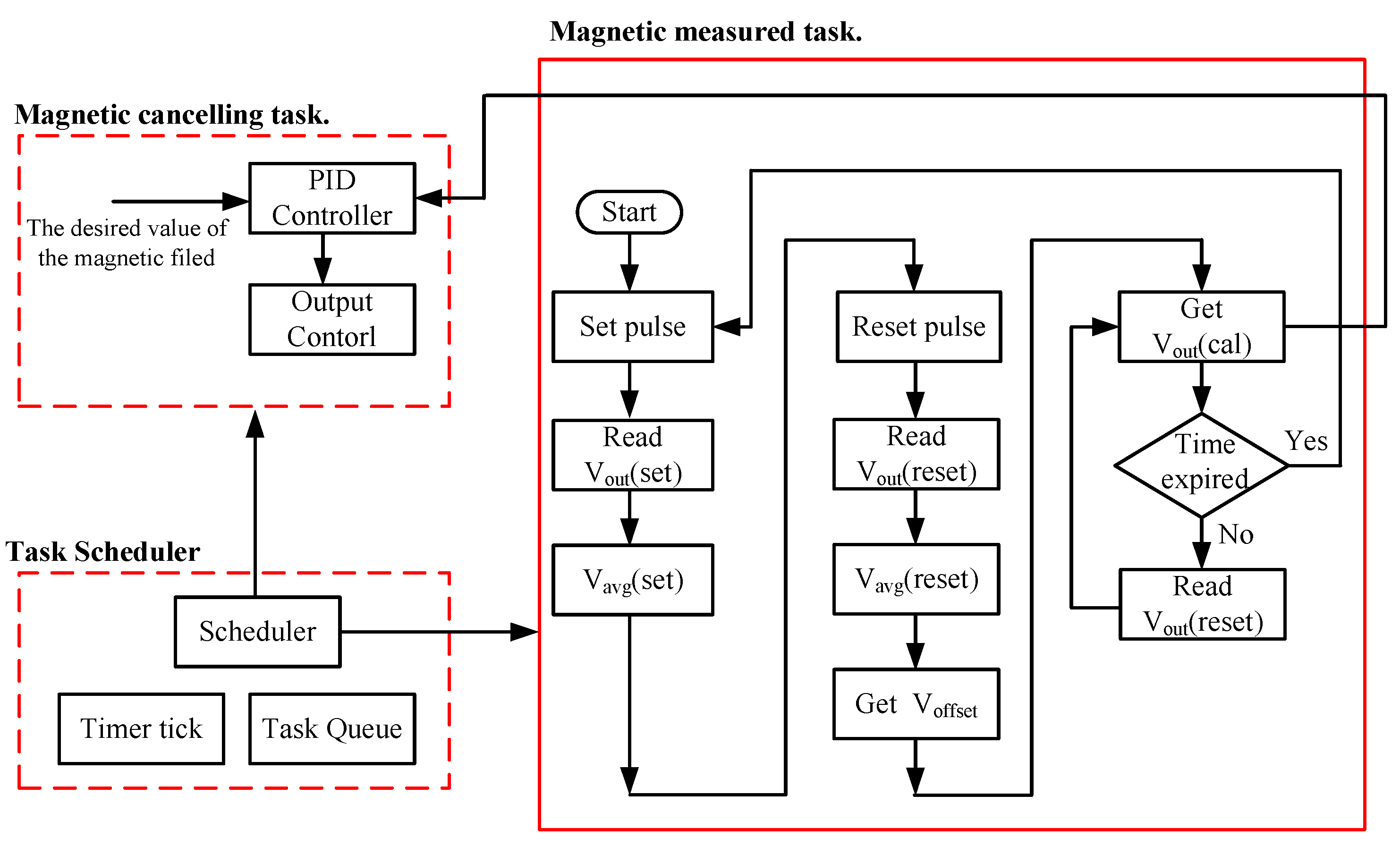
3. Active Magnetic Cancelling Technique
Software Flow Chart of the AMCS System
4. Passive Magnetic Cancelling Technique
4.1. Multi-Layer Structure of PMCS
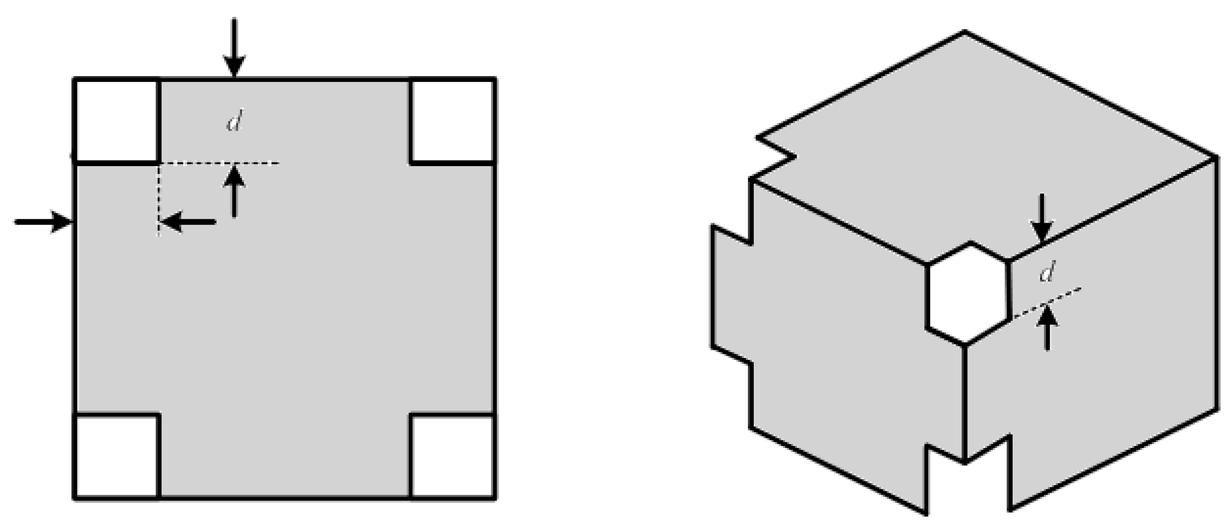
4.2. Shielding Pattern Design
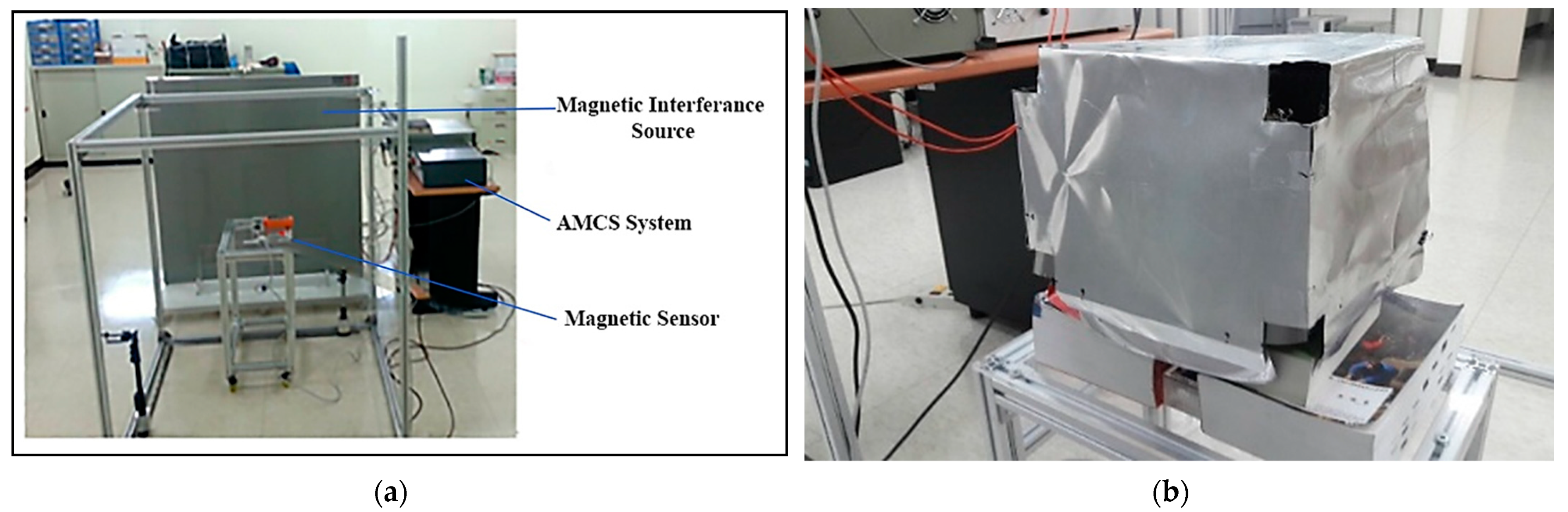
5. Simulation and Experimental Results
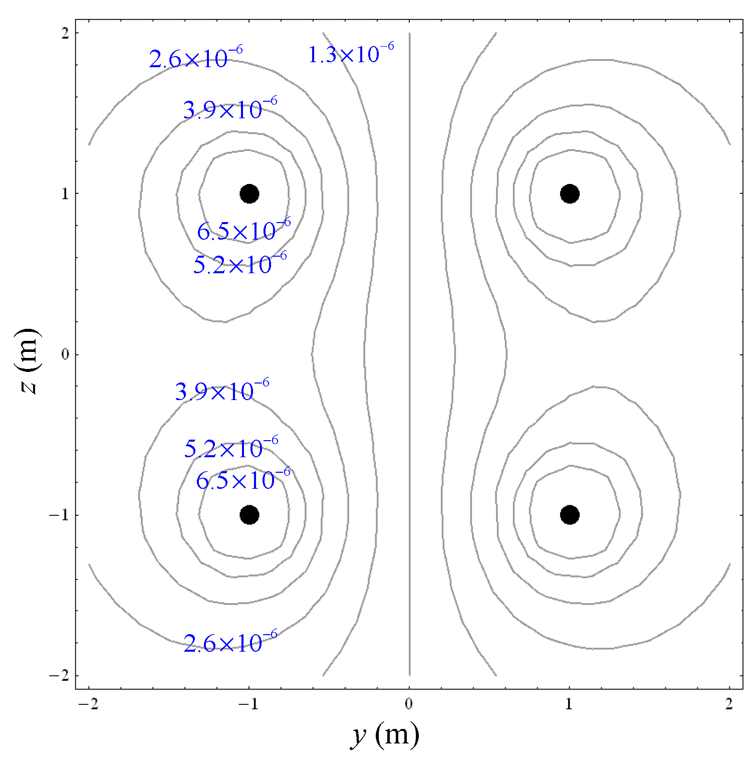
5.1. Numerical Simulation of AMCS
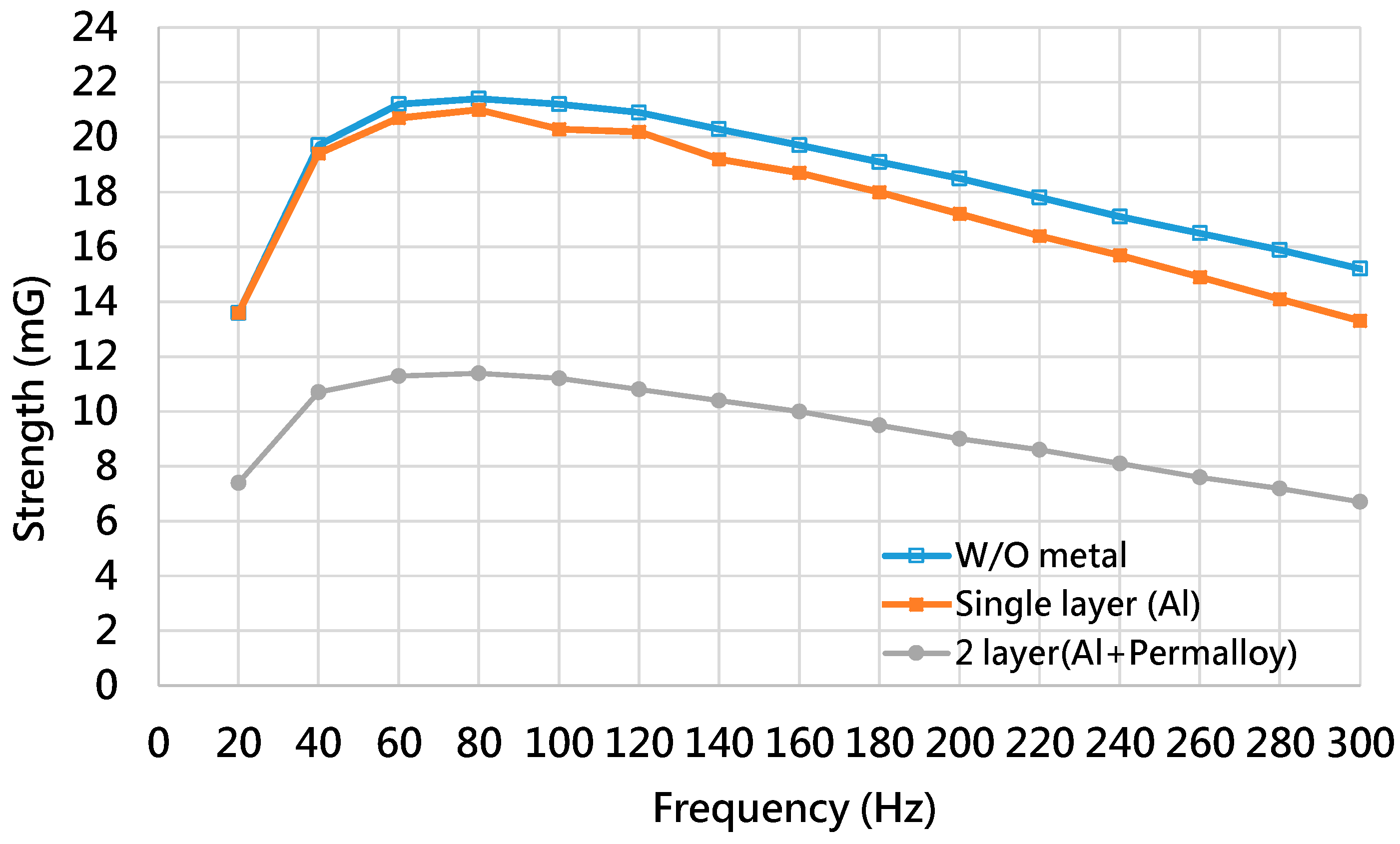
5.2. Shielding Capability of Different Shielding Pattern Designs
6. Conclusions
Author Contributions
Funding
Institutional Review Board Statement
Informed Consent Statement
Data Availability Statement
Conflicts of Interest
References
- Williams, T. Chapter 1—Introduction. In EMC for Product Designers; Newnes: London, UK, 1992; pp. 1–30. ISBN 9780750612647. [Google Scholar] [CrossRef]
- International Agency for Research on Cancer. IARRC Classifies Radiofrequency Electromagnetic Fields as Possibly Carcinogenic to Humans; Press Release No 2008; International Agency for Research on Cancer: Lyon, France, 2011.
- Lopez, J.C.D.P.; Romero, P.C. Influence of Different Types of Magnetic Shields on the Thermal Behavior and Ampacity of Underground Power Cables. IEEE Trans. Power Deliv. 2011, 26, 2659–2667. [Google Scholar] [CrossRef]
- Platzek, D.; Nowak, H.; Giiessler, F.; Röther, J.; Eiselt, M. Active shielding to reduce low frequency disturbances in direct current near biomagnetic measurements. Rev. Sci. Instrum. 1999, 70, 2465–2470. [Google Scholar] [CrossRef]
- Canova, A.; del-Pino-Lόpez, J.C.; Giaccone, L.; Manca, M. Active shielding system for ELF magnetic fields. IEEE Trans. Magn. 2015, 51, 8001004. [Google Scholar] [CrossRef]
- Batista, D.S.; Granziera, F.; Tosin, M.C.; de Melo, L.F. Three-axial Helmholtz coil design and validation for aerospace applications. IEEE Trans. Aerosp. Electron. Syst. 2018, 54, 392–403. [Google Scholar] [CrossRef]
- Kobayashi, K.; Kon, A.; Yoshizawa, M.; Uchikawa, Y. Active magnetic shielding using symmetric magnetic field sensor method. IEEE Trans. Magn. 2012, 48, 4554–4557. [Google Scholar] [CrossRef]
- Barry, R. Time Engineers Ltd. Bristol, United Kingdom. Available online: https://www.freertos.org/features.html (accessed on 5 October 2021).
- Tsai, K.-Y.; Chien, S.-W. High performance environment control system and applications in Helium-Ion-Bean nanofabrication. In Proceedings of the Semicon Taiwan TechXPOT, Zhubei City, Taiwan, 14–16 September 2022. [Google Scholar]
- Li, T.-K. Tri-Axial Square Helmholtz Coil for Neutron EDM Experiment; Department of Physics, the Chinese University of Hong Kong: Hong Kong, China, 2004; Available online: http://www.phy.cuhk.edu.hk/sure/comments_2004/thomasli.pdf (accessed on 18 January 2022).
- da Silva, R.C.; Ishioka, I.S.K.; Cappelletti, C.; Battistini, S.; Borges, R. Helmholtz Cage Design and Validation for Nanosatellites HWIL Testing. IEEE Trans. Aerosp. Elect. Syst. 2019, 55, 3050–3061. [Google Scholar] [CrossRef] [Green Version]
- Pastena, M.; Grassi, M. Optimum design of a three-axis magnetic field simulator. IEEE Trans. Aerosp. Elect. Syst. 2002, 38, 488–501. [Google Scholar] [CrossRef]
- Kirschvink, J.L. Uniform magnetic fields and double wrapped coil systems: Improved Techniques for the design of bioelectromagnetic experiments. Bioelectromagnetics 1992, 13, 401–411. [Google Scholar] [CrossRef] [PubMed]
- Poppenk, F.M.; Amini, R.; Brouwer, G. Design and application of a helmholtz cage for testing nanosatellites. In Proceedings of the 6th International Symposium on Environmental Testing for Space Programmes, Noordwijk, The Netherlands, 12–14 June 2007. [Google Scholar]
- Hurtado-Velasco, R.; Gonzalez-Llorente, J. Simulation of the magnetic field generated by square shap Helmholtz coils. Appl. Math. Model. 2016, 40, 9835–9847. [Google Scholar] [CrossRef]
- Piergentili, F.; Candini, G.P.; Zannoni, M. Design, manufacturing, and test of a real-time, three-axis magnetic field simulator. IEEE Trans. Aerosp. Elect. Syst. 2011, 47, 1369–1379. [Google Scholar] [CrossRef]
- Honeywell International Inc. 2021. Available online: https://aerospace.honeywell.com/en/learn/products/sensors/3-axis-magnetometer (accessed on 21 May 2021).
- Cheng, D.-K. Field and Wave Electromagnetics; Addison-Wesley: Boston, MA, USA, 1989; p. 314. [Google Scholar]
- Arnold, H.D.; Elmen, G.W. Permalloy, a new magnetic material of very high permeability. Bell Syst. Tech. J. 1923, 2, 101–1111. [Google Scholar] [CrossRef]
- Hasselgren, L.; Luomi, J. Geometrical aspects of magnetic shielding at extremely low frequencies. IEEE Transact. Electromagn. Compat. 1995, 37, 409–420. [Google Scholar] [CrossRef]
- Euripides, P. Square Helmholtz Coils. Available online: http://demonstrations.wolfram.com/SquareHelmholtzCoils/ (accessed on 20 July 2021).
- Adame, S.M.; Galvan, J.C.O.; Littlewood, E.C.; Perez, R.E.; Brisset, E.B. Coil systems to generate uniform magnetic field volumes. In Proceedings of the COMSOL Conference, Boston, MA, USA, 7–9 October 2010; pp. 1–7. [Google Scholar]
- Song, Y.-L.; Reddy, M.K.; Lin, H.-Y.; Chang, L.-M. Control of EMI in High-Technology Nano Fab by Exploitation Power Transmission Method with Ideal Permutation. Appl. Sci. 2021, 11, 11984. [Google Scholar] [CrossRef]


| Layer Structure | Layer Structure |
|---|---|
| Single layer | aluminum |
| Double layer | aluminum + Permalloy |
| Items | Value |
|---|---|
| Coil length | 2 m |
| Coil spacing | 2 m |
| Turns of the coil | 8 |
| Coil current | 2.5 A |
| 60 Hz | 120 Hz | |
|---|---|---|
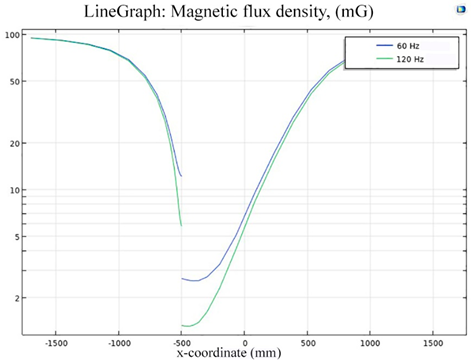
| Box without hole | 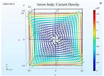 |  |
| Box with 20 cm hole | 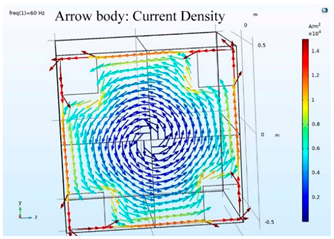 | 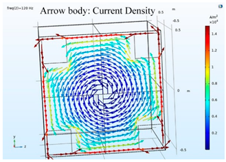 |
| Box with 30 cm hole |  | 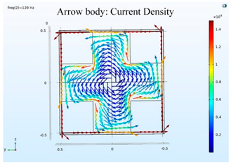 |
| 60 Hz | 120 Hz | |
|---|---|---|
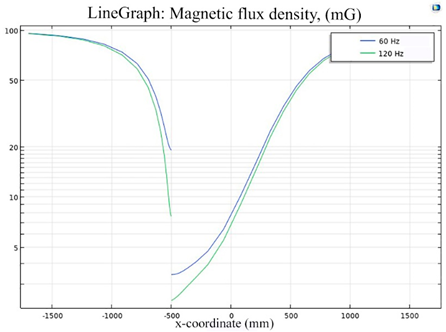
| Box without hole |  |  |
 | ||
| Box with 20 cm hole |  |  |
 | ||
| Box with 30 cm hole | 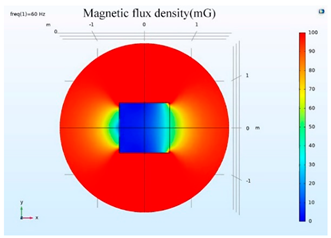 |  |
 | ||
| Box without hole | 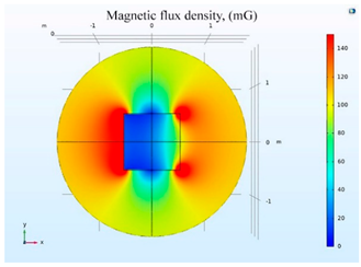 |  |
| Box with 20 cm hole |  |  |
| Box with 30 cm hole |  |  |
| Magnetic Field (mG) | Without Hole | With Hole Hole Size is 20 cm | With Hole Hole Size is 30 cm |
|---|---|---|---|
| 60 Hz | 6.74 | 7.04 | 7.82 |
| 120 Hz | 5.69 | 6.01 | 6.81 |
| DC | 26.16 | 32.105 | 33.48 |
| The Reducing Ratio | Without Hole | With Hole Size is 20 cm | With Hole Size is 30 cm |
|---|---|---|---|
| 60 Hz | 93.26% | 92.96% | 92.18% |
| 120 Hz | 94.31% | 93.99% | 93.19% |
| DC | 73.84% | 67.90% | 66.52% |
| SE (dB) | Without Hole | With Hole Size is 20 cm | With Hole Size is 30 cm |
|---|---|---|---|
| 60 Hz | 23.43 | 23.05 | 22.14 |
| 120 Hz | 24.90 | 24.42 | 23.34 |
| DC | 11.65 | 9.87 | 9.50 |
| With Hole Size is 20 cm | With Hole Size is 30 cm | |
|---|---|---|
| Cost Saving | 16% | 36% |
| Strength (mG)\Frequency | 40 Hz | 60 Hz | 120 Hz | 180 Hz | 240 Hz | 300 Hz |
|---|---|---|---|---|---|---|
| Without shield | 19.7 | 21.2 | 20.9 | 19.1 | 17.1 | 15.2 |
| Single Layer | 19.4 | 20.7 | 20.2 | 18 | 15.7 | 13.3 |
| 2 Layer | 10.7 | 11.3 | 10.8 | 9.5 | 8.1 | 6.7 |
| Improvement (%) single layer vs. 2 layer | 44.8 | 45.41 | 46.53 | 47.22 | 48.41 | 49.62 |
| Improvement (%) without shield vs. 2-layer shield | 45.6 | 46.6 | 50.7 | 50.2 | 52.6 | 55.9 |
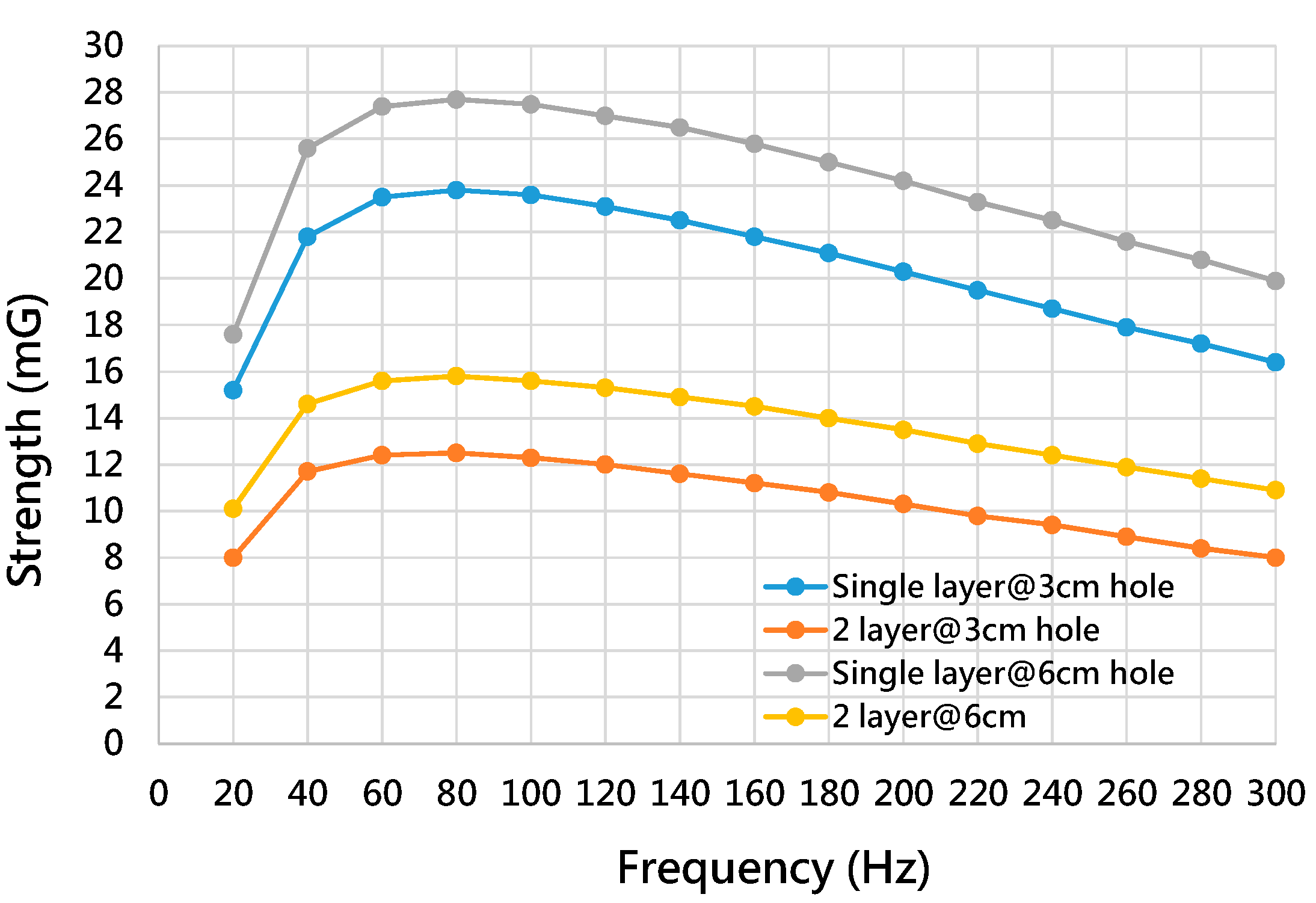
| Strength (mG)\Frequency | 40 Hz | 60 Hz | 120 Hz | 180 Hz | 240 Hz | 300 Hz |
|---|---|---|---|---|---|---|
| Single-layer @6 cm holes | 25.6 | 27.4 | 27 | 25 | 22.5 | 19.9 |
| 2-layer @6 cm holes | 14.6 | 15.6 | 15.3 | 14 | 12.4 | 10.9 |
| Single-layer @3 cm holes | 21.8 | 23.5 | 23.1 | 21.1 | 18.7 | 16.4 |
| 2-layer @3 cm holes | 11.7 | 12.4 | 12 | 10.8 | 9.4 | 8 |
| Improvement (%) for 2-layer @3 cm holes vs. 2-layer@6cm holes | 24.79 | 25.81 | 27.5 | 29.63 | 31.91 | 36.25 |
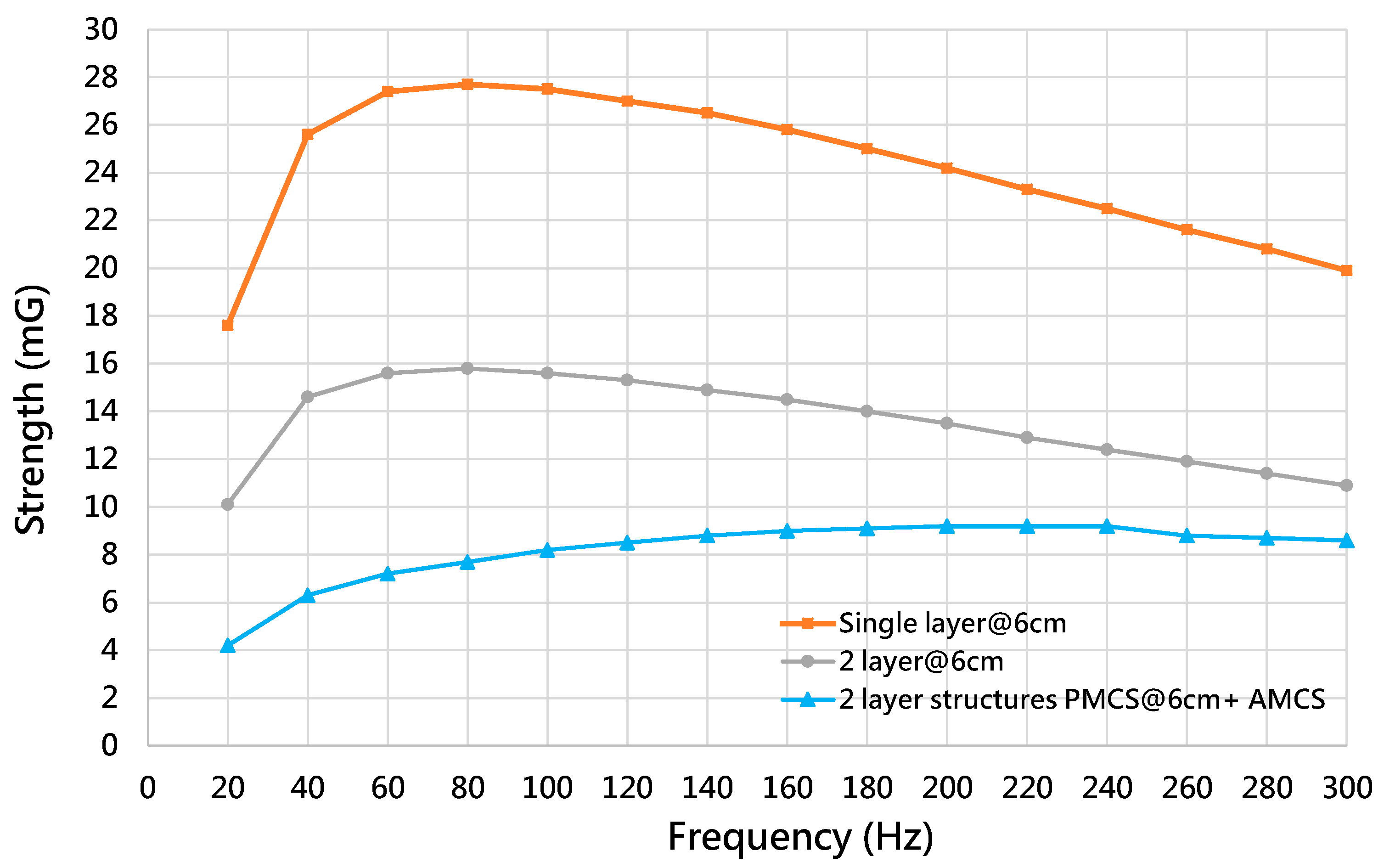
| Strength (mG)\Frequency | 40 Hz | 60 Hz | 120 Hz | 180 Hz | 240 Hz | 300 Hz |
|---|---|---|---|---|---|---|
| Single-layer @6 cm holes | 25.6 | 27.4 | 27 | 25 | 22.5 | 19.9 |
| 2-layer @6 cm holes | 14.6 | 15.6 | 15.3 | 14 | 12.4 | 10.9 |
| 2-layer @6 cm holes + AMCS | 6.3 | 7.2 | 8.5 | 9.1 | 9.2 | 8.6 |
| Improvement (%) 2-layer+AMCS vs. 2-layer | 59.09 | 56.1 | 46.88 | 36.81 | 27.56 | 20.37 |
Publisher’s Note: MDPI stays neutral with regard to jurisdictional claims in published maps and institutional affiliations. |
© 2022 by the authors. Licensee MDPI, Basel, Switzerland. This article is an open access article distributed under the terms and conditions of the Creative Commons Attribution (CC BY) license (https://creativecommons.org/licenses/by/4.0/).
Share and Cite
Song, Y.-L.; Lin, H.-Y.; Manikandan, S.; Chang, L.-M. A Magnetic Field Canceling System Design for Diminishing Electromagnetic Interference to Avoid Environmental Hazard. Int. J. Environ. Res. Public Health 2022, 19, 3664. https://doi.org/10.3390/ijerph19063664
Song Y-L, Lin H-Y, Manikandan S, Chang L-M. A Magnetic Field Canceling System Design for Diminishing Electromagnetic Interference to Avoid Environmental Hazard. International Journal of Environmental Research and Public Health. 2022; 19(6):3664. https://doi.org/10.3390/ijerph19063664
Chicago/Turabian StyleSong, Yu-Lin, Hung-Yi Lin, Saravanan Manikandan, and Luh-Maan Chang. 2022. "A Magnetic Field Canceling System Design for Diminishing Electromagnetic Interference to Avoid Environmental Hazard" International Journal of Environmental Research and Public Health 19, no. 6: 3664. https://doi.org/10.3390/ijerph19063664
APA StyleSong, Y.-L., Lin, H.-Y., Manikandan, S., & Chang, L.-M. (2022). A Magnetic Field Canceling System Design for Diminishing Electromagnetic Interference to Avoid Environmental Hazard. International Journal of Environmental Research and Public Health, 19(6), 3664. https://doi.org/10.3390/ijerph19063664