
Activated Porous Carbon Fiber: New Adsorbent for Sampling and Analysis by Thermal Desorption of Siloxanes in Biogas and Biomethane

 ,
,  ,
,  ,
,  , ,
, , 

Abstract
:1. Introduction
- C8Si3O2H24 + 16 O2 → 3 SiO2 + 8 CO2 + 12 H2O (linear VMS—L3)
- C10Si5O5H30 + 20 O2 → 5 SiO2 + 10 CO2 + 15 H2O (cyclic VMS—D5)
2. Materials and Methods
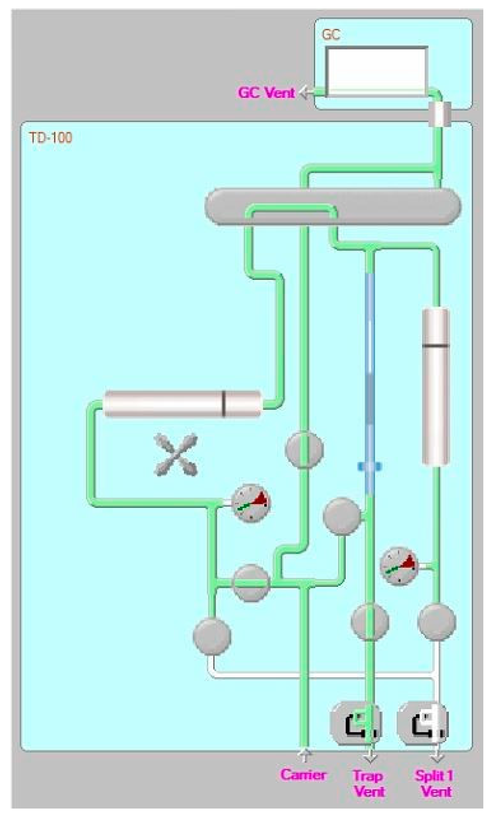
2.1. Instrumental Apparatus
2.2. Sampling Tubes and Focusing Trap: Assembling and Test
2.2.1. Adsorption Phase
2.2.2. Desorption Phase
2.3. Biogas Sampling
3. Results and Discussion
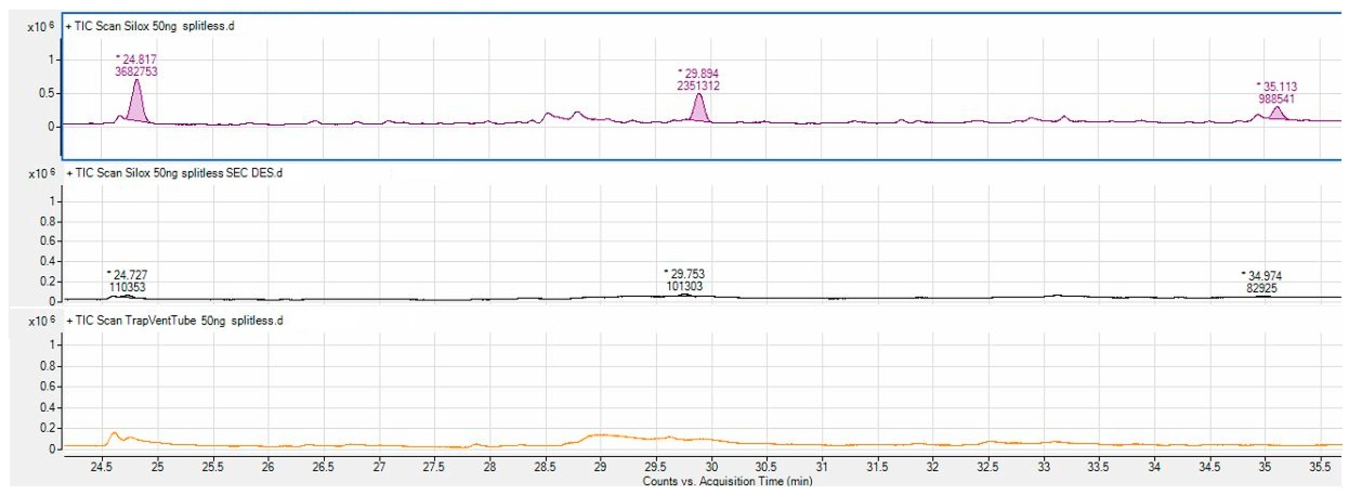
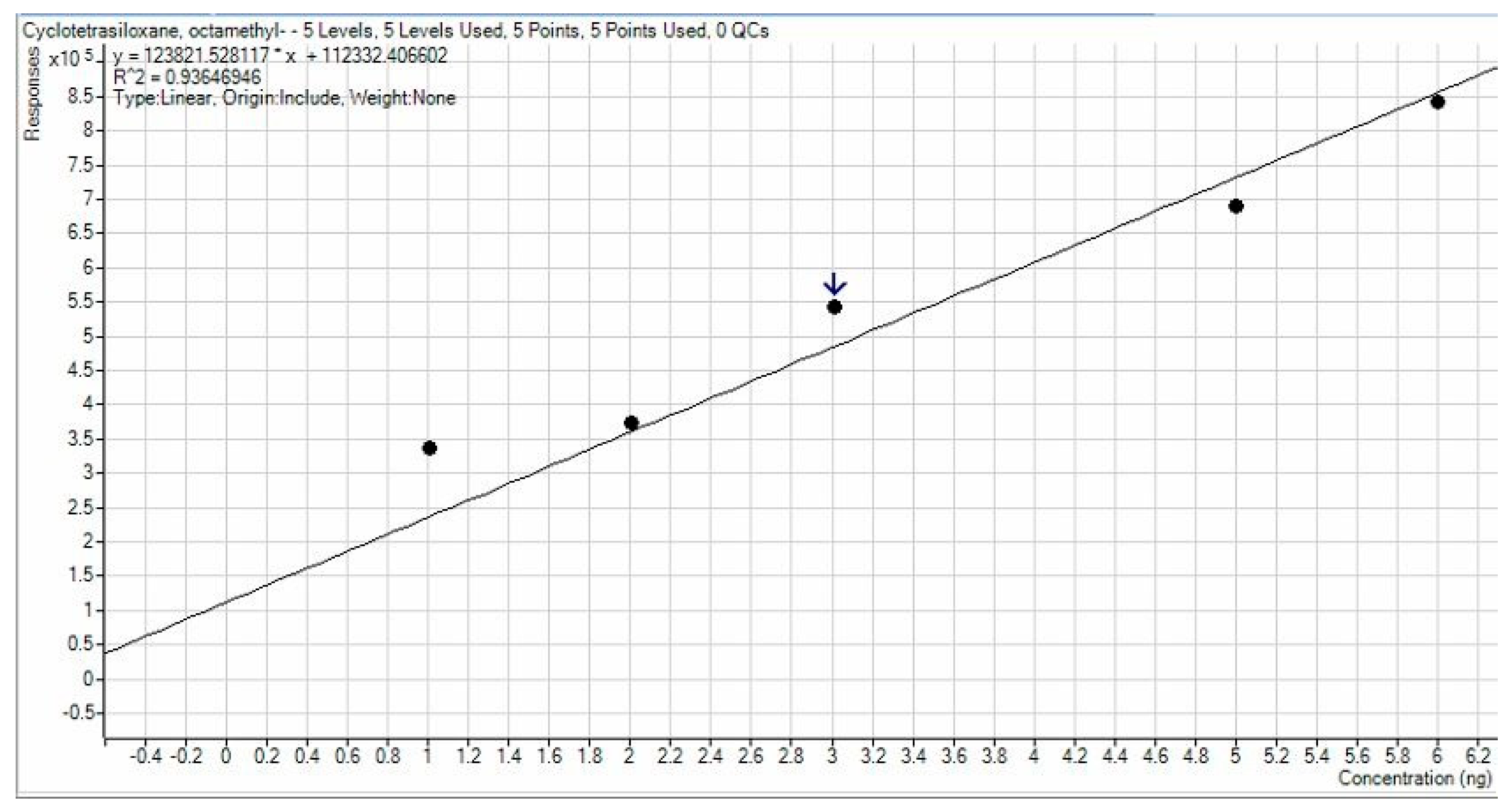
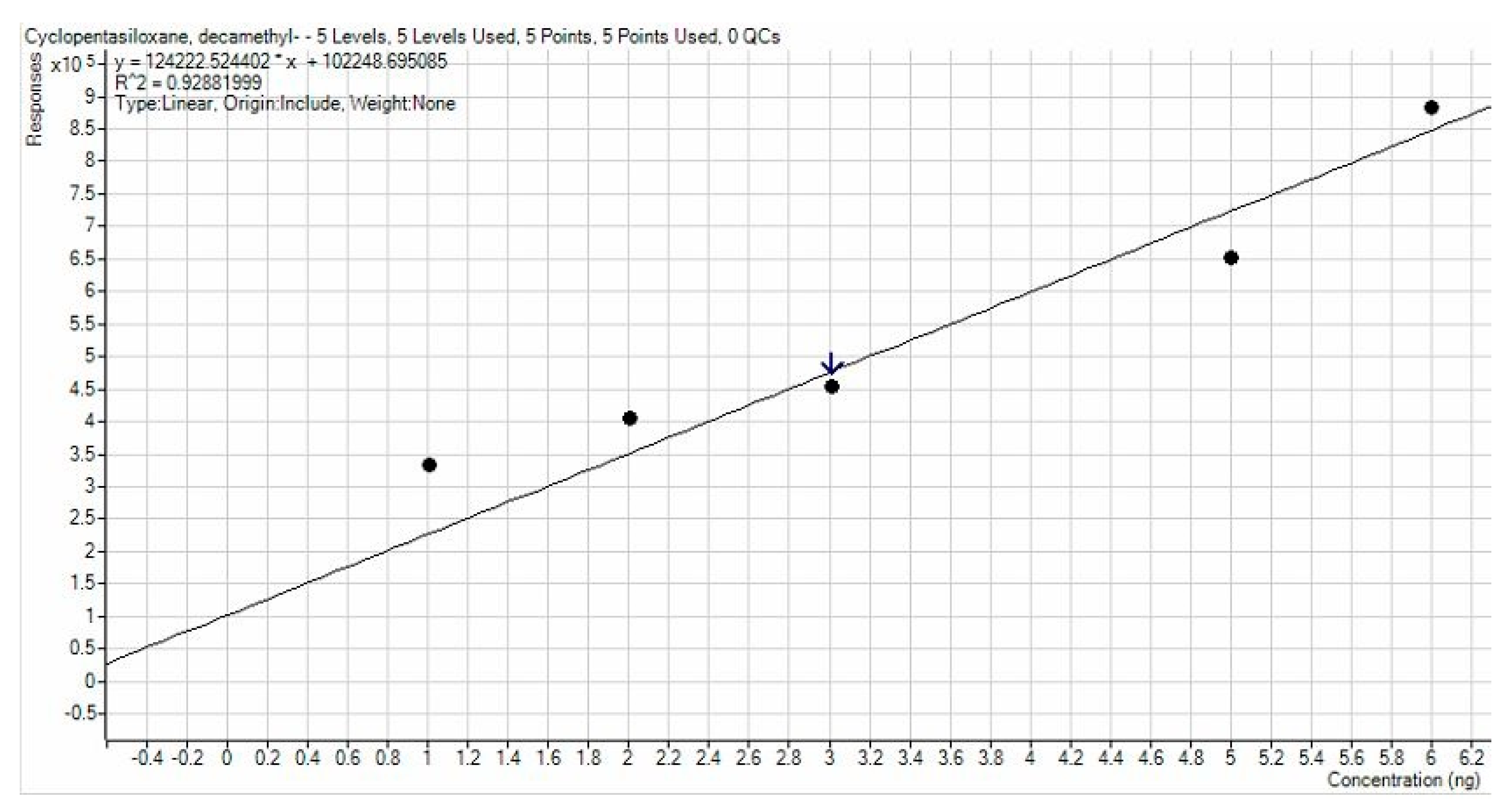
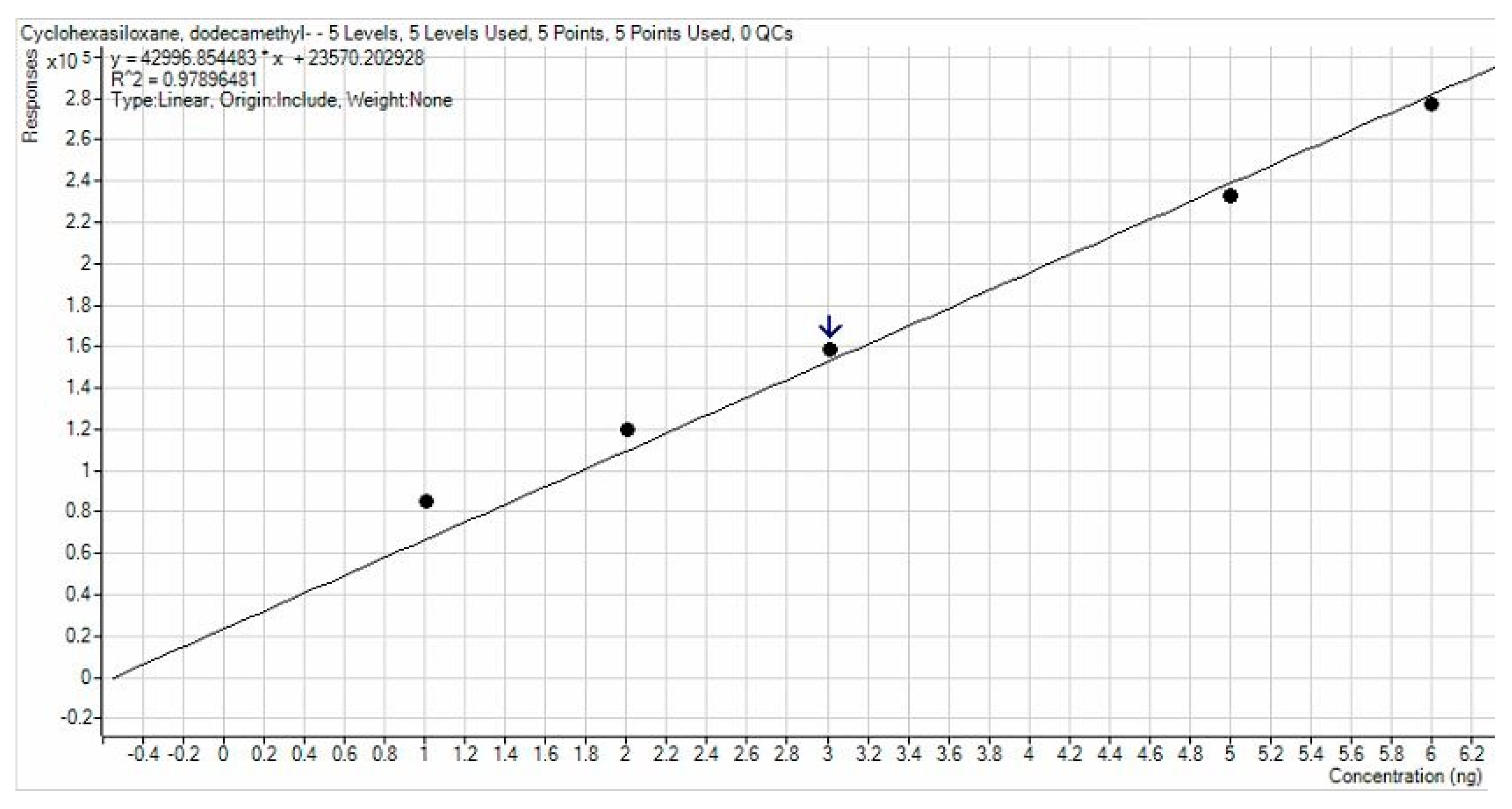
3.1. APCF Efficiency in Thermal Desorption
3.2. Biogas Sampling
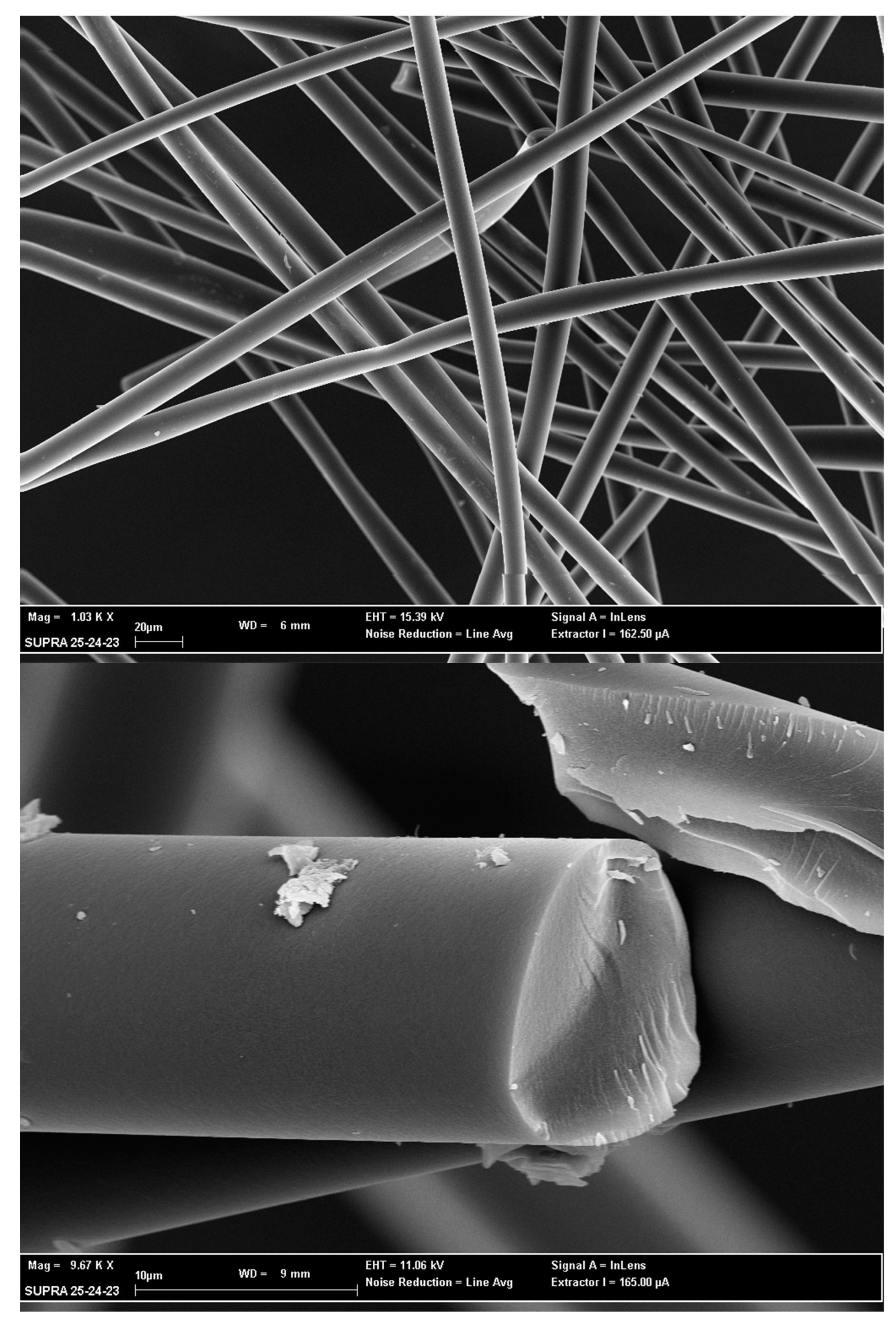
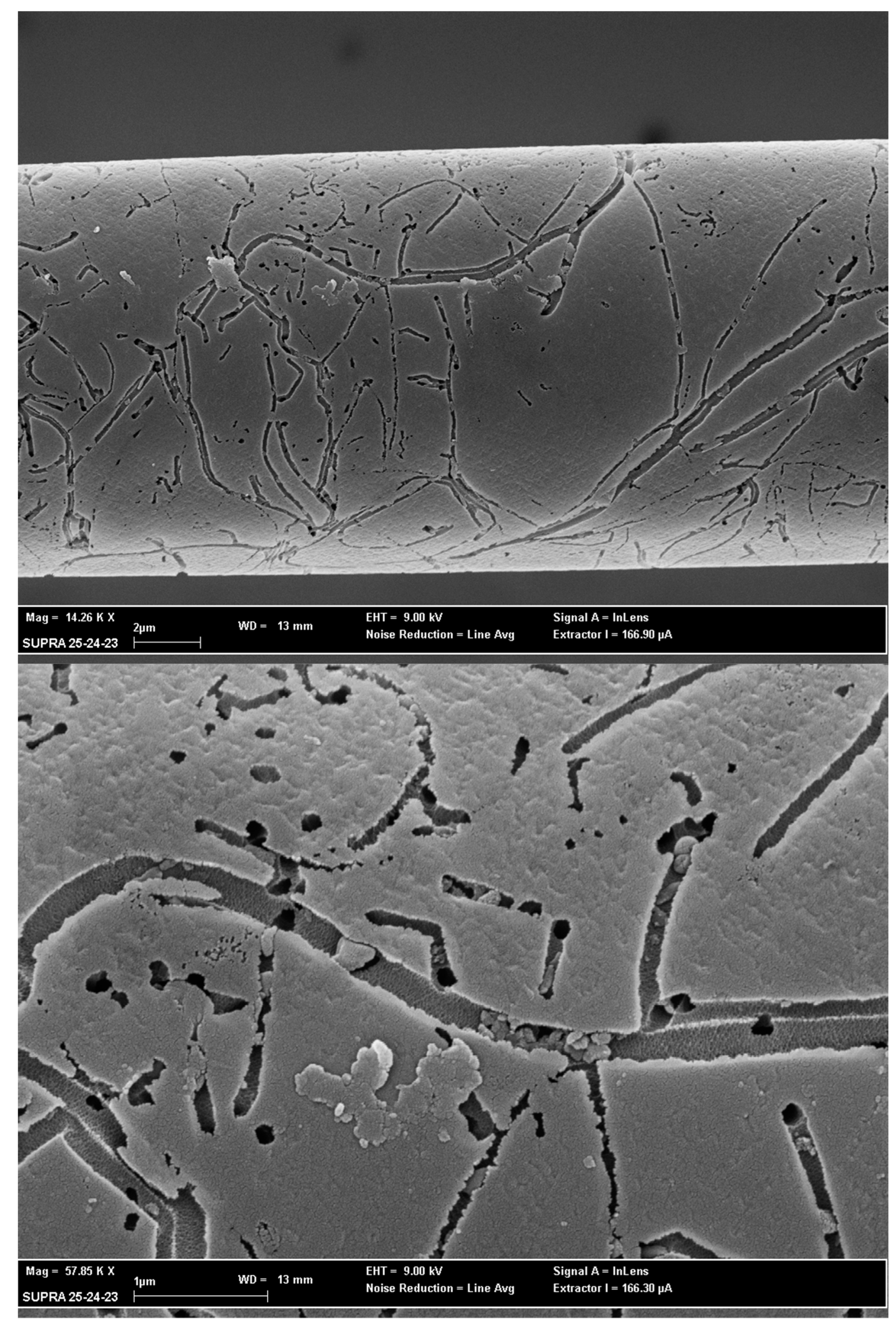
3.3. SEM Analysis
4. Conclusions
Specific and Practical Suggestions
Author Contributions
Funding
Institutional Review Board Statement
Informed Consent Statement
Data Availability Statement
Acknowledgments
Conflicts of Interest
References
- Nriagu, J. Encyclopedia of Environmental Health; Elsevier: Amsterdam, The Netherlands, 2019. [Google Scholar]
- Gaj, K.; Pakuluk, A. Volatile Methyl Siloxanes as Potential Hazardous Air Pollutants. Pol. J. Environ. Stud. 2015, 24, 937–943. [Google Scholar] [CrossRef]
- Piechota, G. Siloxanes in Biogas: Approaches of Sampling Procedure and GC-MS Method Determination. Molecules 2021, 26, 1953. [Google Scholar] [CrossRef] [PubMed]
- Paolini, V.; Petracchini, F.; Carnevale, M.; Gallucci, F.; Perilli, M.; Esposito, G.; Segreto, M.; Occulti, L.G.; Scaglione, D.; Ianniello, A.; et al. Characterisation and Cleaning of Biogas from Sewage Sludge for Biomethane Production. J. Environ. Manag. 2018, 217, 288–296. [Google Scholar] [CrossRef] [PubMed]
- Torre, M.; Borin, D.; Segreto, M.; Tomassetti, L.; Paolini, V.; Petracchini, F.; Paris, E.; Gallucci, F.; Scaglione, D. Siloxanes Concentration and Removal in Biomethane from Sewage Sludge. In Proceedings of the European Biomass Conference and Exhibition Proceedings, Bologna, Italy, 27 May 2019. [Google Scholar]
- Arnold, M. Reduction and Monitoring of Biogas Trace Compounds. VTT Tied. Res. Notes 2009, 2496, 27. [Google Scholar]
- Bragança, I.; Sánchez-Soberón, F.; Pantuzza, G.F.; Alves, A.; Ratola, N. Impurities in Biogas: Analytical Strategies, Occurrence, Effects and Removal Technologies. Biomass Bioenergy 2020, 143, 105878. [Google Scholar] [CrossRef]
- Bak, C.U.; Lim, C.J.; Lee, J.G.; Kim, Y.D.; Kim, W.S. Removal of Sulfur Compounds and Siloxanes by Physical and Chemical Sorption. Sep. Purif. Technol. 2019, 209, 542–549. [Google Scholar] [CrossRef]
- Latimer, H.K.; Kamens, R.M.; Chandra, G. The Atmospheric Partitioning of Decamethylcyclopentasiloxane (D5) and 1-Hydroxynonamethylcyclopentasiloxane (D4TOH) on Different Types of Atmospheric Particles. Chemosphere 1998, 36, 2401–2414. [Google Scholar] [CrossRef]
- Wheless, E.; Pierce, J. Siloxanes in Landfill and Digester Gas Update. SCS Engineers. Environmental Consultants and Contractors. 2004, p. 10. Available online: https://www.scsengineers.com/scs-white-papers/siloxanes-in-landfill-and-digester-gas-update/ (accessed on 28 August 2022).
- Monteith, H.; Yajima, K.; Andrews, D.; Steel, P. Assessing Feasibility of Direct Drive Technology for Energy Recovery from Digester Biogas. Proc. Water Environ. Fed. 2014, 2006, 3517–3540. [Google Scholar] [CrossRef]
- Huppmann, R.; Lohoff, H.W.; Schröder, H.F. Cyclic Siloxanes in the Biological Waste Water Treatment Process—Determination, Quantification and Possibilities of Elimination. Fresenius’ J. Anal. Chem. 1996, 354, 66–71. [Google Scholar] [CrossRef]
- Varaprath, S.; Frye, C.L.; Hamelink, J. Aqueous Solubility of Permethylsiloxanes (Silicones). Environ. Toxicol. Chem. 1996, 15, 1263–1265. [Google Scholar] [CrossRef]
- Kochetkov, A.; Smith, J.S.; Ravikrishna, R.; Valsaraj, K.T.; Thibodeaux, L.J. Air-Water Partition Constants for Volatile Methyl Siloxanes. Environ. Toxicol. Chem. 2001, 20, 2184–2188. [Google Scholar] [CrossRef] [PubMed]
- Dewil, R.; Appels, L.; Baeyens, J. Energy Use of Biogas Hampered by the Presence of Siloxanes. Energy Convers. Manag. 2006, 47, 1711–1722. [Google Scholar] [CrossRef]
- Appels, L.; Baeyens, J.; Degrève, J.; Dewil, R. Principles and Potential of the Anaerobic Digestion of Waste-Activated Sludge. Prog. Energy Combust. Sci. 2008, 34, 755–781. [Google Scholar] [CrossRef]
- Brooke, D.N.; Brooke, M.J.; Gray, D.; Robertson, S.; Crookes, M.; Gray, D.; Robertson, S. Environmental Risk Assessment Report: Octamethylcyclotetrasiloxane; Environmental Agency: Bristol, UK, 2009. [Google Scholar]
- Van Egmond, R.; Sparham, C.; Hastie, C.; Gore, D.; Chowdhury, N. Monitoring and Modelling of Siloxanes in a Sewage Treatment Plant in the UK. Chemosphere 2013, 93, 757–765. [Google Scholar] [CrossRef] [PubMed]
- Howard, P.H.; Muir, D.C.G. Identifying New Persistent and Bioaccumulative Organics among Chemicals in Commerce. Environ. Sci. Technol. 2010, 44, 2277–2285. [Google Scholar] [CrossRef] [PubMed]
- Kierkegaard, A.; McLachlan, M.S. Determination of Decamethylcyclopentasiloxane in Air Using Commercial Solid Phase Extraction Cartridges. J. Chromatogr. A 2010, 1217, 3557–3560. [Google Scholar] [CrossRef]
- Hagmann, M.; Heimbrand, E.; Hentschel, P. Determination of Siloxanes in Biogas from Landfills and Sewage Treatment Plants. SÖFW J. 2002, 128, 3–7. [Google Scholar]
- Schweigkofler, M.; Niessner, R. Determination of Siloxanes and VOC in Landfill Gas and Sewage Gas by Canister Sampling and GC-MS/AES Analysis. Environ. Sci. Technol. 1999, 33, 3680–3685. [Google Scholar] [CrossRef]
- Mulu, E.; M’Arimi, M.M.; Ramkat, R.C. A Review of Recent Developments in Application of Low Cost Natural Materials in Purification and Upgrade of Biogas. Renew. Sustain. Energy Rev. 2021, 145, 111081. [Google Scholar] [CrossRef]
- Soreanu, G.; Béland, M.; Falletta, P.; Edmonson, K.; Svoboda, L.; Al-Jamal, M.; Seto, P. Approaches Concerning Siloxane Removal from Biogas—A Review. Can. Biosyst. Eng. 2011, 53, 8.1–8.18. [Google Scholar]
- Arnold, M.; Kajolinna, T. Development of On-Line Measurement Techniques for Siloxanes and Other Trace Compounds in Biogas. Waste Manag. 2010, 30, 1011–1017. [Google Scholar] [CrossRef] [PubMed]
- Khan, M.U.; Lee, J.T.E.; Bashir, M.A.; Dissanayake, P.D.; Ok, Y.S.; Tong, Y.W.; Shariati, M.A.; Wu, S.; Ahring, B.K. Current Status of Biogas Upgrading for Direct Biomethane Use: A Review. Renew. Sustain. Energy Rev. 2021, 149, 111343. [Google Scholar] [CrossRef]
- Hagmann, M.; Hesse, E.; Hentschel, P.; Bauer, T. Purification of Biogas—Removal of Volatile Silicones. In Proceedings of the Sardinia 2001, Eighth International Waste Management and Landfill Symposium, Sardinia, Italy, 1–5 October 2001. [Google Scholar]
- Piechota, G. Biogas/Biomethane Quality and Requirements for Combined Heat and Power (CHP) Units/Gas Grids with a Special Focus on Siloxanes-a Short Review. Sustain. Chem. Eng. 2021, 3, 1–10. [Google Scholar] [CrossRef]
- Niemann, M. Characterization of Si Compounds in Landfill Gas. In Proceedings of the Solid Waste Association of North America’s 20th Annual Landfill Gas Symposium, Monterey, CA, USA, 25–27 March 1997. [Google Scholar]
- Saeed, S.; Kao, S.; Graening, G. Determination of Siloxanes in Air Using Methanol-Filled Impingers and Analyzed by Gas Chromatography/Mass Spectrometry (GC/MS). In Proceedings of the 1st Annual GTI Natural Gas Technologies Conference, Orlando, FL, USA, 10 September 2002. [Google Scholar]
- Brymer, D.A.; Ogle, L.D.; Jones, C.J.; Lewis, D.L. Viability of Using SUMMA Polished Canisters for the Collection and Storage of Parts per Billion by Volume Level Volatile Organics. Environ. Sci. Technol. 1996, 30, 188–195. [Google Scholar] [CrossRef]
- Lampe, S. Assessment of Fuel Gas Cleanup Systems for Waste Gas Fueled Power Generation; EPRI (Electric Power Research Institute): Palo Alto, CA, USA, 2006; Volume 3. [Google Scholar]
- Seo, D.-C.; Yun, S.; Kim, M.-J.; Oh, I.-K.; And, S.-S.S.; Chun, S.-K. Experimental Study on the Removal of Siloxane from Landfill Gas by Adsorption. Proc. Sard. Margherita Di Pula 2007, 1, 1–7. [Google Scholar]
- Rossol, D.; Schmelz, K.G. Siloxane Im Faulgas. GWF Wasser Abwasser 2005, 146, 55–61. [Google Scholar]
- Paris, E.; Carnevale, M.; Vincenti, B.; Palma, A.; Guerriero, E.; Borello, D.; Gallucci, F. Evaluation of VOCs Emitted from Biomass Combustion in a Small CHP Plant: Difference between Dry and Wet Poplar Woodchips. Molecules 2022, 27, 955. [Google Scholar] [CrossRef]
- Saha, D.; Grappe, H.A. Adsorption Properties of Activated Carbon Fibers. In Activated Carbon Fiber and Textiles; Woodhead Publishing: Sawston, UK, 2017. [Google Scholar]

| Abbreviation | D4 | D5 | D6 |
|---|---|---|---|
| Name | Octamethylcyclo-Tetrasiloxan | Decamethylcyclo-Pentasiloxane | Dodecamethylcyclo-Hexasiloxane |
| Structure | 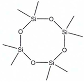 |  | 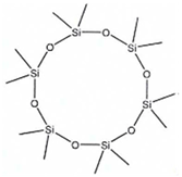 |
| Molecular Formula | C8H24O4Si4 | C10H30O5Si5 | C12H36O6Si6 |
| Physical Properties | Liquid, colorless, oily, odorless | Liquid, oily | Liquid, colorless, faint odor |
| Molecular weight (Da) | 296.61 | 370.80 | 444.93 |
| Boiling point (°C) | 175.5 | 210 | 245 |
| Melting point (°C) | 17.5 | 7.5 | −3 |
| Water solubility (mg/Lw 23 °C) | 0.056 | 0.017 | 0.005 |
| Molar Volume (g/cm3 at 20 °C) | 309.2 | 386.5 | 463.8 |
| Density (g/cm3) at 20 °C | 0.953 | 0.955 | 0.959 |
| Critical T (°C) | 313.35 | 346.05 | 382.25 |
| Critical P (atm) | 13.2 | 11.5 | 12.9 |
| Critical V (m3/kmol) | 979.0 | 1216.0 | 1493.1 |
| Operative Parameters | ||
|---|---|---|
| TD | Desorption time | 10 min |
| Desorption flow | 60 mL min–1 | |
| Desorption temperature | 365 °C | |
| Focusing trap temperature | −15 °C | |
| Focusing trap desorption temperature | 370 °C | |
| GC/MS | Carrier gas | He |
| Column | DB 502.2 | |
| Flow | 1.2 mL min–1 | |
| GC mode | constant flow | |
| Oven ramp | 35 °C (5 min) + 5 °C min–1 to 230 °C (5 min) | |
| Ion source | EI | |
| Inlet temperature | 200 °C | |
| MS source temperature | 230 °C | |
| Transfer line Temperature | 240 °C | |
| MS mode | Full Scan 35–450 m/z | |
| Carbon Fiber Continent (%) | Fiber Diameter (μm) | Specific Surface Area (m2 g–1) | Density (g cm–3) | |
|---|---|---|---|---|
| ACPF 1 | 100 | 10 | ≈2000 | 0.095 |
| I Desorption Test | II Desorption Test | Residue % | Backup Tube | |
|---|---|---|---|---|
| D4 | 3,682,753 | 110,353 | 3.0 | <LOD |
| D5 | 2,351,312 | 101,303 | 4.3 | <LOD |
| D6 | 988,541 | 82,925 | 8.4 | <LOD |
| APCF | D4 | D5 | D6 |
|---|---|---|---|
| Average | 0.182 | 0.488 | 0.101 |
| Standard Deviation | 0.030 | 0.083 | 0.009 |
| Multilayers Tube | D4 | D5 | D6 |
| Average | 0.076 | 0.035 | 0.120 |
| Standard Deviation | 0.010 | 0.034 | 0.112 |
Publisher’s Note: MDPI stays neutral with regard to jurisdictional claims in published maps and institutional affiliations. |
© 2022 by the authors. Licensee MDPI, Basel, Switzerland. This article is an open access article distributed under the terms and conditions of the Creative Commons Attribution (CC BY) license (https://creativecommons.org/licenses/by/4.0/).
Share and Cite
Paris, E.; Avino, P.; Guerriero, E.; Vincenti, B.; Palma, A.; Carnevale, M.; Benedetti, P.; Torre, M.; Gallucci, F. Activated Porous Carbon Fiber: New Adsorbent for Sampling and Analysis by Thermal Desorption of Siloxanes in Biogas and Biomethane. Int. J. Environ. Res. Public Health 2022, 19, 10890. https://doi.org/10.3390/ijerph191710890
Paris E, Avino P, Guerriero E, Vincenti B, Palma A, Carnevale M, Benedetti P, Torre M, Gallucci F. Activated Porous Carbon Fiber: New Adsorbent for Sampling and Analysis by Thermal Desorption of Siloxanes in Biogas and Biomethane. International Journal of Environmental Research and Public Health. 2022; 19(17):10890. https://doi.org/10.3390/ijerph191710890
Chicago/Turabian StyleParis, Enrico, Pasquale Avino, Ettore Guerriero, Beatrice Vincenti, Adriano Palma, Monica Carnevale, Paolo Benedetti, Marco Torre, and Francesco Gallucci. 2022. "Activated Porous Carbon Fiber: New Adsorbent for Sampling and Analysis by Thermal Desorption of Siloxanes in Biogas and Biomethane" International Journal of Environmental Research and Public Health 19, no. 17: 10890. https://doi.org/10.3390/ijerph191710890
APA StyleParis, E., Avino, P., Guerriero, E., Vincenti, B., Palma, A., Carnevale, M., Benedetti, P., Torre, M., & Gallucci, F. (2022). Activated Porous Carbon Fiber: New Adsorbent for Sampling and Analysis by Thermal Desorption of Siloxanes in Biogas and Biomethane. International Journal of Environmental Research and Public Health, 19(17), 10890. https://doi.org/10.3390/ijerph191710890