1. Introduction
Light microscopy based on magnification using an objective lens is widely used as one of the simplest and easiest methods for observing various tissues at the cellular level. Among the techniques for image acquisition, the use of a microscope is a direct method useful for observing and analyzing morphological changes with respect to various conditions. Although a light microscope can be used to most easily observe the changes in the tissue, it is limited in observing fine parts owing to the limitations of spatial resolution and noise amplification. Thus, it is essential to improve the qualities of light microscopic images for accurate analysis [
1]. The approach of development of hardware and software technologies is mainly used to improve the microscopic image quality. The development field of hardware technology for improving microscopic images is the most suitable method to achieve a desired level of image quality, but has a large disadvantage of high cost. Thus, methods using image processing technologies are actively studied [
2,
3,
4].
Generally, a light microscopy image can be mathematically modelled as a linear-translation-invariant system incorporating the background noise [
5]:
where
g is the image obtained by containing distortion components in the
x- and
y-coordinates,
f is a clean image,
psf is the point-spread function (PSF), which indicates the degree of blurring occurring owing to the finite imaging system (e.g., focal spot, pixel size), and
represents the two-dimensional (2D) convolution operator, which is used to obtain the
by predicting and measuring the
to perform the deconvolution.
N is the background signal dominated by Poisson and Gaussian noises. In light microscopy images, obtained by numerous photons, the Poisson noise can be assumed as an additive Gaussian noise [
6]. Therefore, it is very important to perform an accurate
psf prediction while effectively controlling the noise.
To overcome these difficulties, image deconvolution algorithms have been studied to obtain successfully restored images under the conditions of an unknown PSF containing the image degradation rate of the imaging system, including the Bayesian method, inverse Radon transform, iteration methods, and deep-learning approaches [
7,
8,
9,
10,
11,
12,
13]. These methods were used to obtain a considerably effective result for the ill-posed problem. However, one of the main difficulties of these methods is associated with the presence of noise in the microscopy image, because the noise component prompts an imperfect edge detection and often leads to an unstable or false solution owing to finding the inexact PSF. Moreover, the noise should be amplified by the deconvolution process as a side effect.
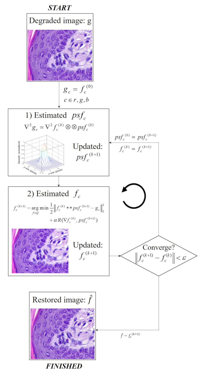
A typical approach to controlling the noise while implementing the deconvolution method is to solve the inverse problem using appropriate regularization terms,
where
is the regularization term used to compensate the noise component to calculate the error in the part of
. This approach enables effective PSF estimation and image restoration, even in images with noise.
is observed in several
lp-norm-based priors including the
lp-norm-based prior (
p decreases at regular intervals while iterating) [
14], normalized sparsity-based image prior [
15], approximate
l0-norm-based image prior [
16], and reweighted
l2-norm-based image prior [
17]. However, these approaches have limitations, including the staircase artifacts (cartooned artifacts) in
l2-norm-based minimization [
18] and noise amplification in sparse deconvolution by
l1-norm-based minimization [
19]. Shao et al. [
20] introduced the bi-
l0-
l2-norm regularization strategy with an effective performance decreasing the computational cost to restore the degraded images. Their strategy improves the accuracy of the kernel estimation owing to the strategy of evasion from the background noise.
The objective of this study was to apply the bi-
l0-
l2-norm regularization strategy in light microscopy. For that objective, quantitative evaluations, including visual assessment, intensity profile, root-mean-square error (RMSE) [
21], edge preservation index (EPI) [
22], structural similarity index measure (SSIM) [
23], and normalized noise power spectrum (NNPS) [
24] were used in both simulation and experiment images. We used the compressed sensing (CS) [
25,
26,
27,
28] and conjugate gradient (CG) [
29] methods to solve the optimization problem with a high accuracy.
Section 2 briefly describes the bi-
l0-
l2-norm regularization strategy in blind deconvolution and study conditions.
Section 3 presents the results and discussion, while
Section 4 summarizes the conclusions of this study.
3. Results and Discussion
In the simulation, we use a numerical star phantom (ISO 15775, Siemens star test chart, image size = 2000 × 2000 pixels) to measure the system resolution by the degree of distinction between line pairs. The phantom has a diameter of 400 µm with 36 pairs of spokes (bright and dark regions) with a pixel pitch of 1.7 µm.
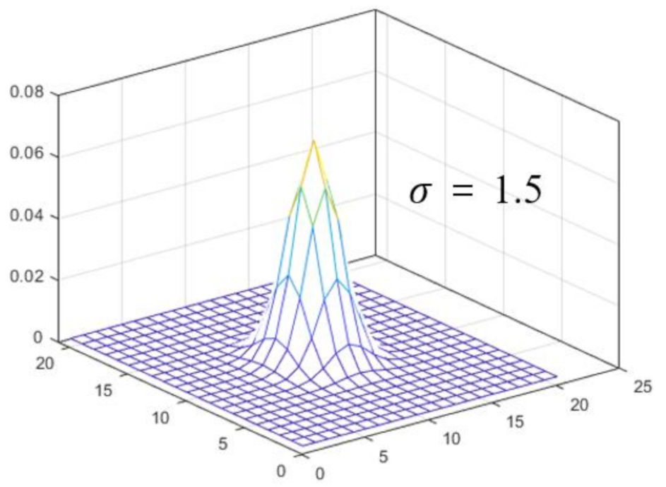
Figure 2 shows a 3D plot of the PSF used to convolve the clean image. The PSF is based on a Gaussian distribution (kernel size = 51 × 51 pixels, sigma = 1.5 pixels). We perform the convolution to obtain a blurred image using the clean image and PSF. In addition, white noise with a Gaussian distribution (mean = 0, variation = 0.01) is added to the blurred image to synthesize the degraded image.
Microscopic images of haematoxylin–eosin (H–E) staining in a mouse oral mucosa were acquired for this study. The H–E-stained tissue was produced according to the general histological sample preparation, including fixation in 4% paraformaldehyde, paraffin embedding, tissue sectioning (7 µm), and H–E staining. The microscope images were acquired using a Leica series imaging system (Leica Microsystem, Germany), which consisted of a Leica DM500 microscope (40×/0.65 NA/0.31 mm W.D., 100×/1.25 NA/0.10 mm W.D.), Leica ICC50 E camera (Aptina 1/2 inch CMOS sensor, pixel size = 3.2 µm × 3.2 µm, pixel resolution = 2048 × 1536), and Leica LAS EZ software.
The simulations and experiments were performed using MATLABTM (MathWorks, Natick, MA, USA, R2019a) (computer hardware: central processing unit: Intel, Santa Clara, CA, USA, Xeon Platinum 8168 @ 2.70 GHz; random-access memory: Samsung, South Korea, 8G×4 DDR4 21300; graphics processing unit (GPU): NVIDIA, Santa Clara, CA, USA, GTX 1080 11 GB). The proposed blind deconvolution method required less than 2 s with the GPU parallel processing, which confirms its utility for practical applications.
We measured the profile, RMSE, EPI, SSIM, and NNPS, to evaluate the image quality using the proposed blind deconvolution framework. Among these evaluation parameters, the NPS evaluation parameter was used to calculate the noise of the microscope image based on the distribution in the frequency domain. NPS describes the retention and noise amplitudes of imaging system, including microscopes, and is a parameter that can accurately represent uncertainty and inaccuracies from system signals. In this study, the NPS was measured by introducing the concept of non-uniform gain in a microscopic image shape model with fixed noise. Based on the measured NPS, we normalized to derive the final NNPS result. Regarding the NNPS, the noise characteristic of the image is measured to evaluate the spectrum.
where
is the detector pixel size, and
represents the Fourier transform operator. The NNPS measures the change in the noise amplitude as a function of the spatial frequency and bridges the noise and spatial resolution characteristics of an image.
Figure 3 shows the simulation results, including the reference image, degraded image (Equation (1)), and image restored using the proposed method. In order to visually analyze the acquired image more clearly, two parts were enlarged and shown below the representative image.
The enlarged images of boxes B and C indicate that the resolution of the restored image is closer to the resolution of the reference image than to that of the degraded image. By observing the pattern on the edge of the acquired simulation image, we confirmed that blurring occurred in the degraded image in the all areas, and in particular, the restored image showed a very similar pattern to the reference image. In addition, the degree of image degradation on the edge side of the degraded image was confirmed to be such that there was not much difficulty in visual observation. However, as a result of observing center area of the degraded image, it was confirmed that the noise amplification and the patterns were clearly blurred compared to the reference image. As a result of applying the proposed algorithm, the image in the center area was reliably improved, and we can solve the problem of image quality deterioration, which is the most important part when observing a microscopic image of a tissue.
Moreover,
Figure 4 shows enlarged patches of the three images in
Figure 3 for the background areas marked with box
A. We confirmed that the patch distribution was obtained differently in each of the three images. In particular, the proposed method was successfully used for blind deconvolution while minimizing the noise amplification.
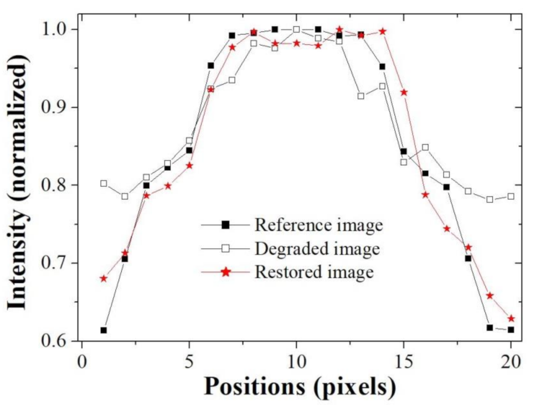
Figure 5 shows the resultant profile measured along the broken red line in
Figure 3 with box
C. It confirms that the blurring rate of the restored image profile is smaller than that of the degraded image and that the profile of the restored image is similar to that of the reference image. In the profile result graph, it was confirmed that the difference between the reference image and the degraded image was very large at both ends, and the difference tended to decrease as the direction of the pixel position in the middle was increased. Likewise, the profile result of the restored image showed a similar trend as above result, but the width of change was significantly reduced. Moreover, the same tendency is observed in the image evaluation through the quantitative measurement through image quality evaluation factors.
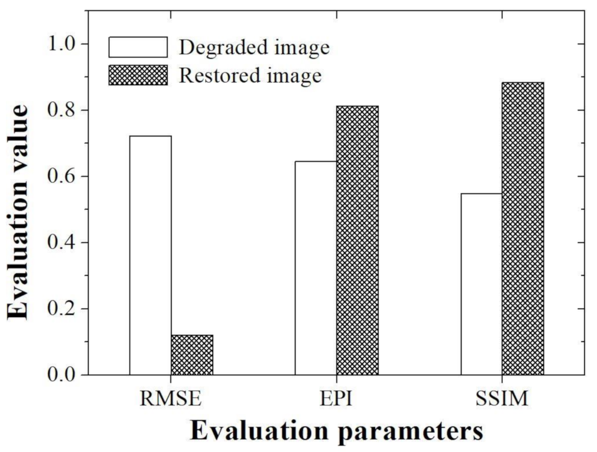
Figure 6 shows the evaluation values obtained using the RMSE, EPI, and SSIM with simulation images.
According to the recently published papers by Saha et al., it can be confirmed that RMSE parameter is used as a quantitative index for the analysis of the utility of deep learning techniques in 3D microscopy images [
31]. In addition, according to a study conducted at Linden et al., the RMSE evaluation parameter was used to confirm the difference between true and estimation data when analyzing the usefulness of the image super resolution algorithm for microscope images [
32]. In this study, RMSE evaluation parameter was also used to determine how much the proposed method was improved compared to the degraded image when compared with the reference image. The acquired RMSEs are about 0.72 and 0.12 for the degraded and restored images, respectively. In particular, we demonstrated that RMSE value of the image to which the proposed method was applied is approximately six times higher than the value measured in the degraded image.
In microscopic images, when information on an edge area of an acquired tissue image is lost, a situation in which it is difficult to distinguish it from an adjacent tissue often occurs. However, most of the evaluation of the edge information to demonstrate the usefulness of the image processing technology in the microscope image is performed visually or using a profile. Recently, methods for evaluating the sharpness index of an image based on no-reference including the blind/referenceless image spatial quality evaluator or image quality evaluator parameter have been developed and used [
33,
34,
35]. In researches by Kim et al., a no-reference-based method was used to evaluate the noise removal efficiency that is not revealed in the visual evaluation when the denoising algorithm is applied to the light microscopy image [
1]. However, since this index has the disadvantage that it cannot accurately measure edge information, it is rarely used as a general method for microscopic image evaluation. Thus, in this study, we tried to evaluate the edge preserving ability of the proposed algorithm using accurate EPI evaluation parameters, which are widely used in other imaging fields. The acquired EPIs are about 0.65 and 0.81 for the degraded and restored images, respectively. In particular, we demonstrated that EPI value of the image to which the proposed method was applied is approximately 1.3 times higher than the value measured in the degraded image. Based on our EPI results, the improvement of the edge information of the tissue light microscopic image is expected to contribute to the precise analysis of the shape of teeth as well as the ability to more clearly determine the boundary between the hard tissue and soft tissue, which are difficult to distinguish.
The SSIM is a method of measuring structural distortion under the assumption that the evaluation of the degree of loss of image quality is caused by the structural distortion of the signal itself rather than by a certain type of error. This method measures image quality through a top-down approach starting from the overall point of view, and can complement the limitations of the error sensitivity approach by observing luminance, contrast, and structure in complex parameters [
36]. SSIM can measure the subjectively perceived image quality of distorted images, so it can be widely used in tissue images using a light microscope. The acquired SSIMs are about 0.54 and 0.88 for the degraded and restored images, respectively. We demonstrated that SSIM value of the image to which the proposed method was applied is approximately 1.6 times higher than the value measured in the degraded image. In addition, it was confirmed that the high SSIM value when the proposed algorithm was used in the light microscopic image of the oral mucosa used in this study can achieve more accurate embryology and anatomical information in the local area.
These results indicate that the proposed algorithm well estimates the PSF using the single image while controlling the noise amplification.
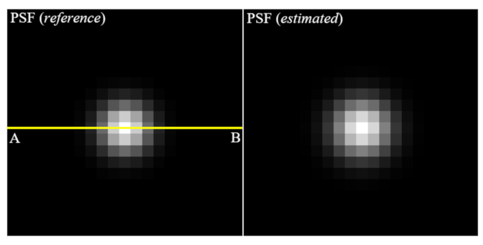
Figure 7 shows the images of PSF (reference) to make the blurred image and PSF (estimated) using the proposed algorithm. Note that it can be seen that these profiles are almost similar. For the quantitative evaluation,
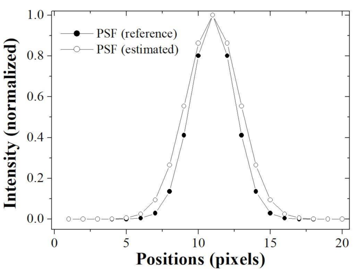
Figure 8 shows that the profiles of two PSF at line AB is almost close.
Here, the profile implemented the Gaussian fitting based on the extracted results. The sigma of PSF (reference) was measured as 1.5 pixels and the that of PSF (estimated) was measured as 1.84 pixels. Accurately estimation of PSF means that successful image restoration is possible and implies that a method of repeatedly updating the PSF and image (blind-deconvolution method) is successfully performed.
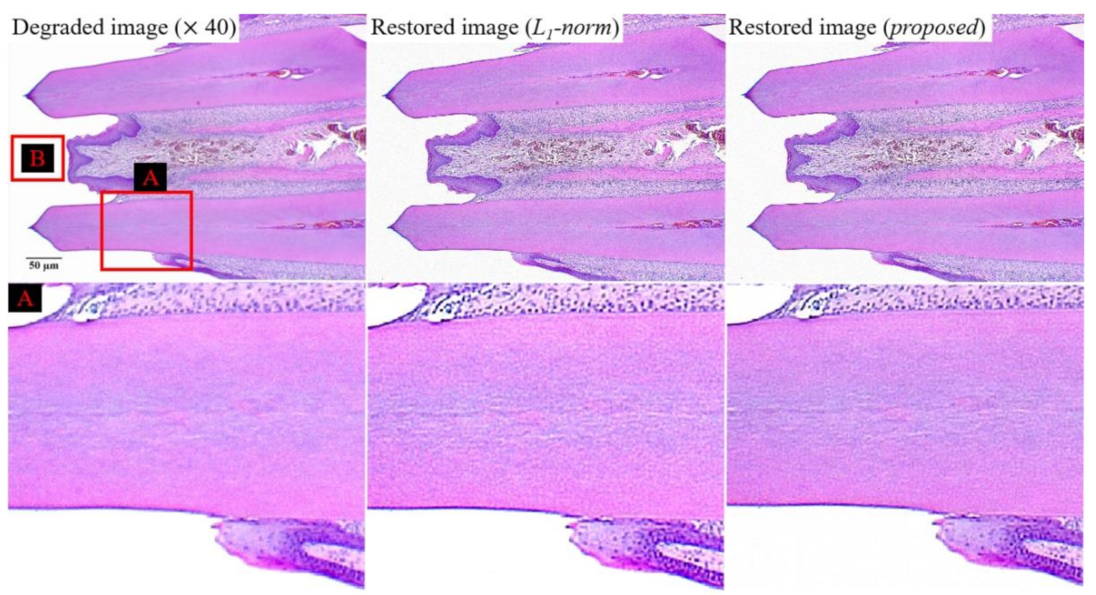
Figure 9 shows the experiment results for the degraded image at a magnification of 40, restored image (
l1-norm), and restored image (proposed). To compare the effectiveness of the bi-
l0-
l2-norm-based regularization, we used the
l1-norm-based regularization,
All parameters in Equation (6) are used identically to those in Equation (4). The enlarged image (box
A in
Figure 9) restored using the proposed method exhibits a similar sharpness improvement to that of the comparative image
(l1-norm-based restored image), at a smaller amplification of the noise. The tendency of these results can be confirmed by images with a higher magnification.
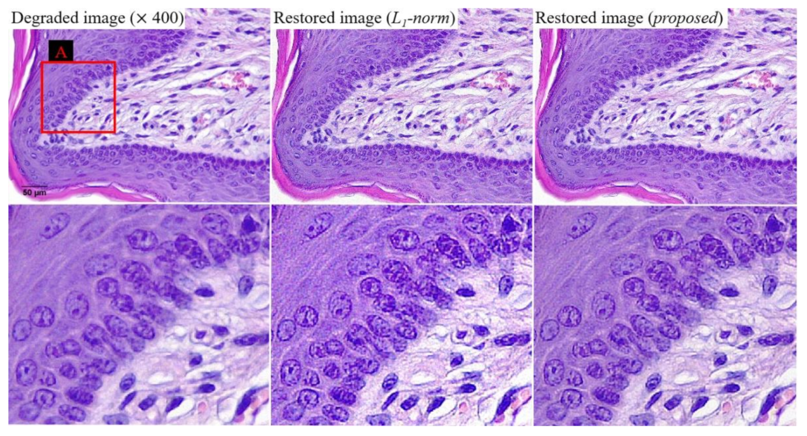
Figure 10 shows examples of the three images at a magnification of 400. We confirmed the improvement of sharpness while suppressing the noise amplification as a result of
Figure 9. This result indicates that the proposed algorithm can produce effective results, even in various magnification images. For the quantitative evaluation of noise characteristics,
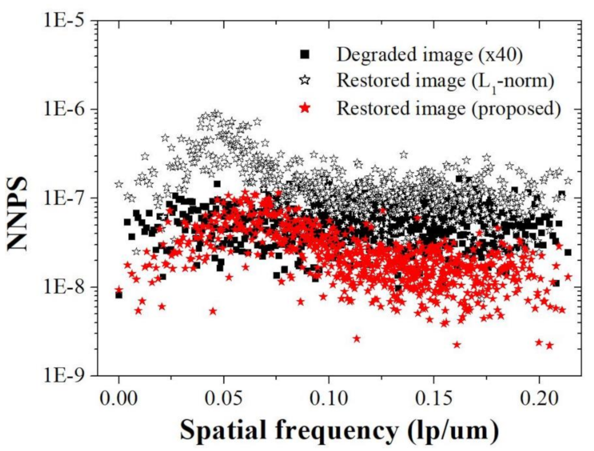
Figure 11 shows that the NNPS characteristics of the restored image (proposed) at spatial frequencies over about 0.10 lp/μm are improved compared to those of the degraded image (×40) and restored image (
l1-norm), owing to the bi-
l0-
l2-norm regularization penalty. These results demonstrate that the proposed method effectively improves the resolution when noise is present in the light microscope image.
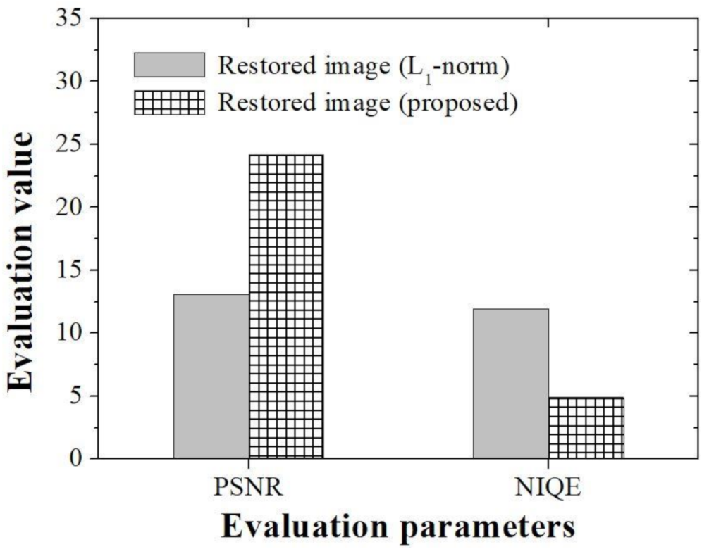
In order to compare and evaluate the degree of restoration according to the type of algorithm in the real experimental image, the peak signal to noise ratio (PSNR) and the natural image quality evaluator (NIQE) [
34], which is a representative no-reference-based evaluation parameter (
Figure 12), were used. Since there is no gold standard image in the real experimental image, a parameter that can compare the whole image was used. We derived PSNR results of 13.10 and 24.18, respectively, when using the conventional
l1-norm method and the proposed method. In addition, the NIQE evaluation results were 11.92 and 4.90, respectively, when the conventional
l1-norm method proposed method were used. In particular, the differences between PSNR and NIQE in the two methods were 1.84 and 2.44 times, respectively. The proposed method, which has small mean square error value that can analyze the restoration rate of an image and the variation between pixels, is expected to be able to better distinguish tissues in microscopic images. In particular, the improved NIQE results are expected to be of great help in applying a deep learning approach that required measuring the distance between features acquired form an image database in the future.
Light microscope is used mainly to generate magnified images of small objects. It has been used in biology because it can be easily operated. However, limitations exist in light microscopy, including the resolution and magnification. A light microscope with transmitted light at a very high magnification can distort the image of a point object [
37]. The resolution of the light microscope is a measure of the microscope’s ability to distinguish two adjacent structures. In particular, the size of diffraction and resolving power of a microscopic image are determined by the wavelength and number of apertures of the objective lens. According to these results, it is challenging to clearly distinguish adjacent areas in light microscopy images [
38]. One of the approaches to fully utilize the capabilities of the microscope is to obtain a sufficiently high magnification. However, the light microscope has a lower resolution than those of other systems because of the diffuse propagation of the refracted light waves from the lens, which leads to blurred images. Therefore, we applied the bi-
l0-
l2-norm regularization strategy as the image processing technology to improve the qualities of microscopic images. The proposed method will contribute to studies using microscopes as basic systems.
In addition, this study was limited to subjective and quantitative analysis of the applicability of the proposed algorithm in microscopic images. In the future, based on the results of this study, we will conduct a subjective evaluation for users such as imaging experts, doctors, and radiologists to further analyze usefulness.
