
Systematic Review of Clinical Applications of CAD/CAM Technology for Craniofacial Implants Placement and Manufacturing of Orbital Prostheses


Abstract
:1. Introduction
2. Experimental Section
2.1. Search Strategy
2.2. Eligibility Criteria
2.3. Source of Information
2.4. Study Selection
2.5. Data Extraction
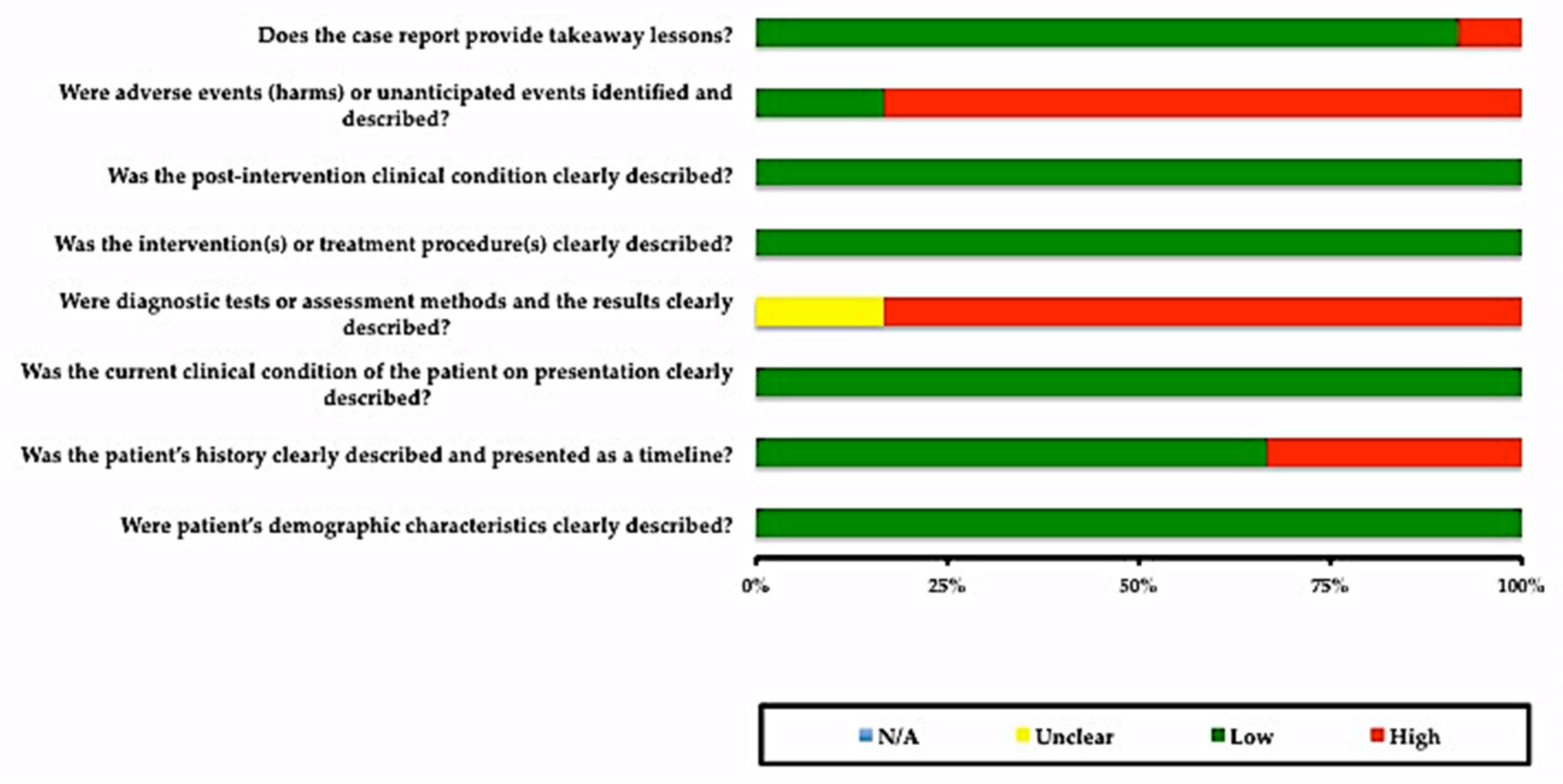
2.6. Risk of Bias in Individual Studies
3. Results
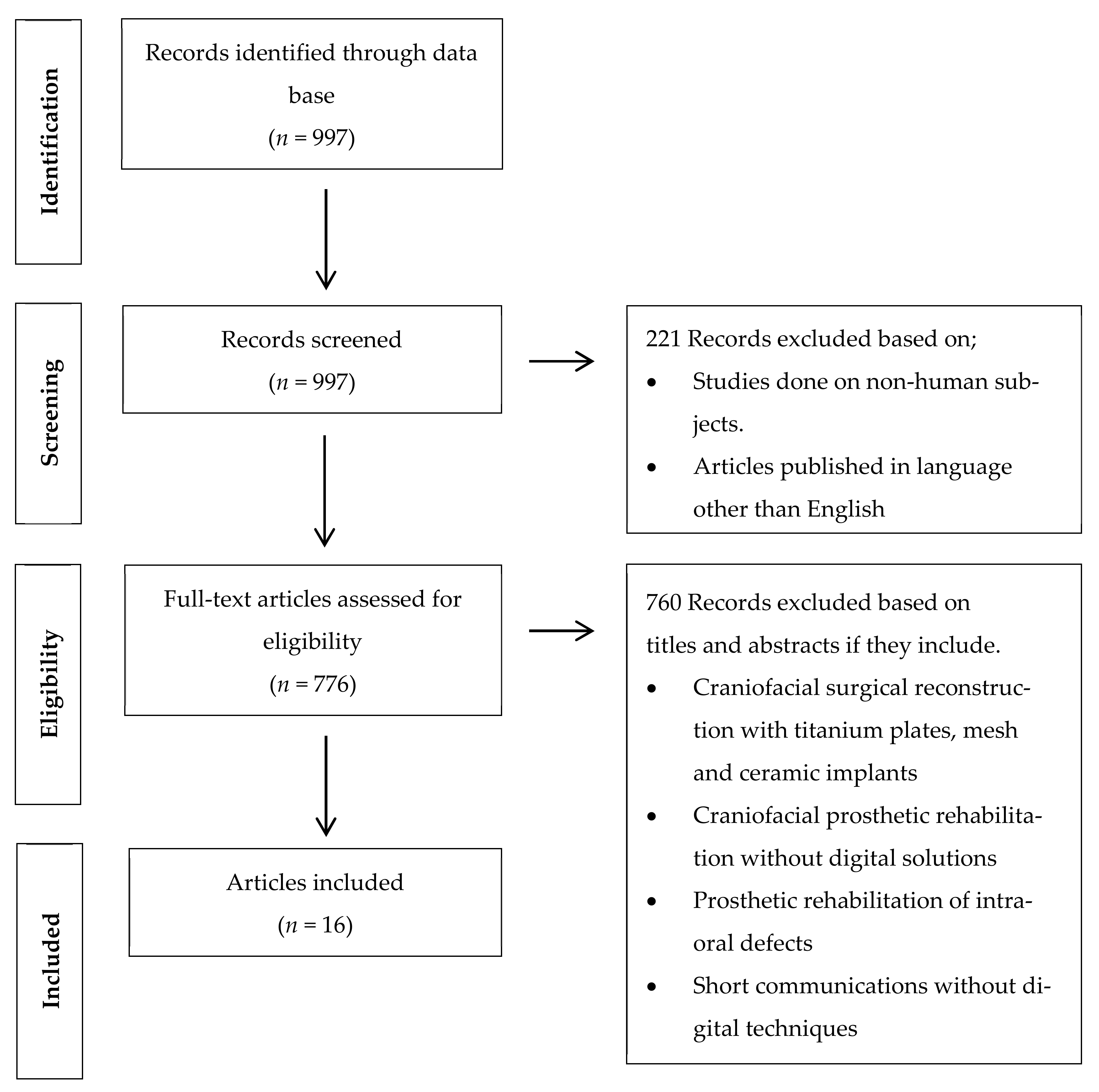
3.1. Study Selection
3.2. Study Characteritics
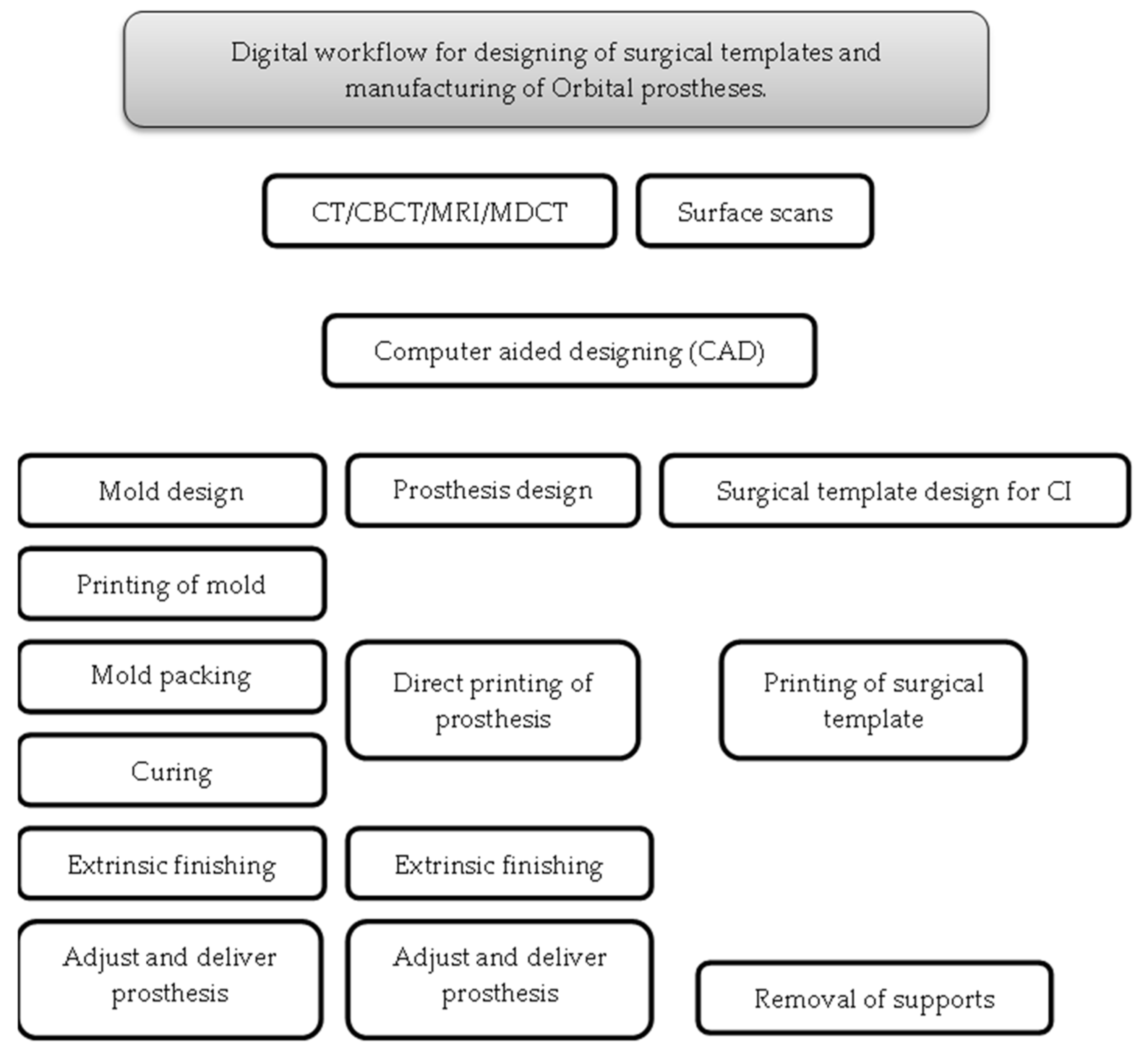
3.2.1. Applications of CAD/CAM Technology for Surgical and Prosthetic Purposes
3.2.2. Preoperative Record for Digital Planning
3.2.3. Preoperative Record for Digital Designing
3.2.4. Printing Systems Utilized for Surgical and Prosthetic Phases
3.2.5. Guided Implants Surgery
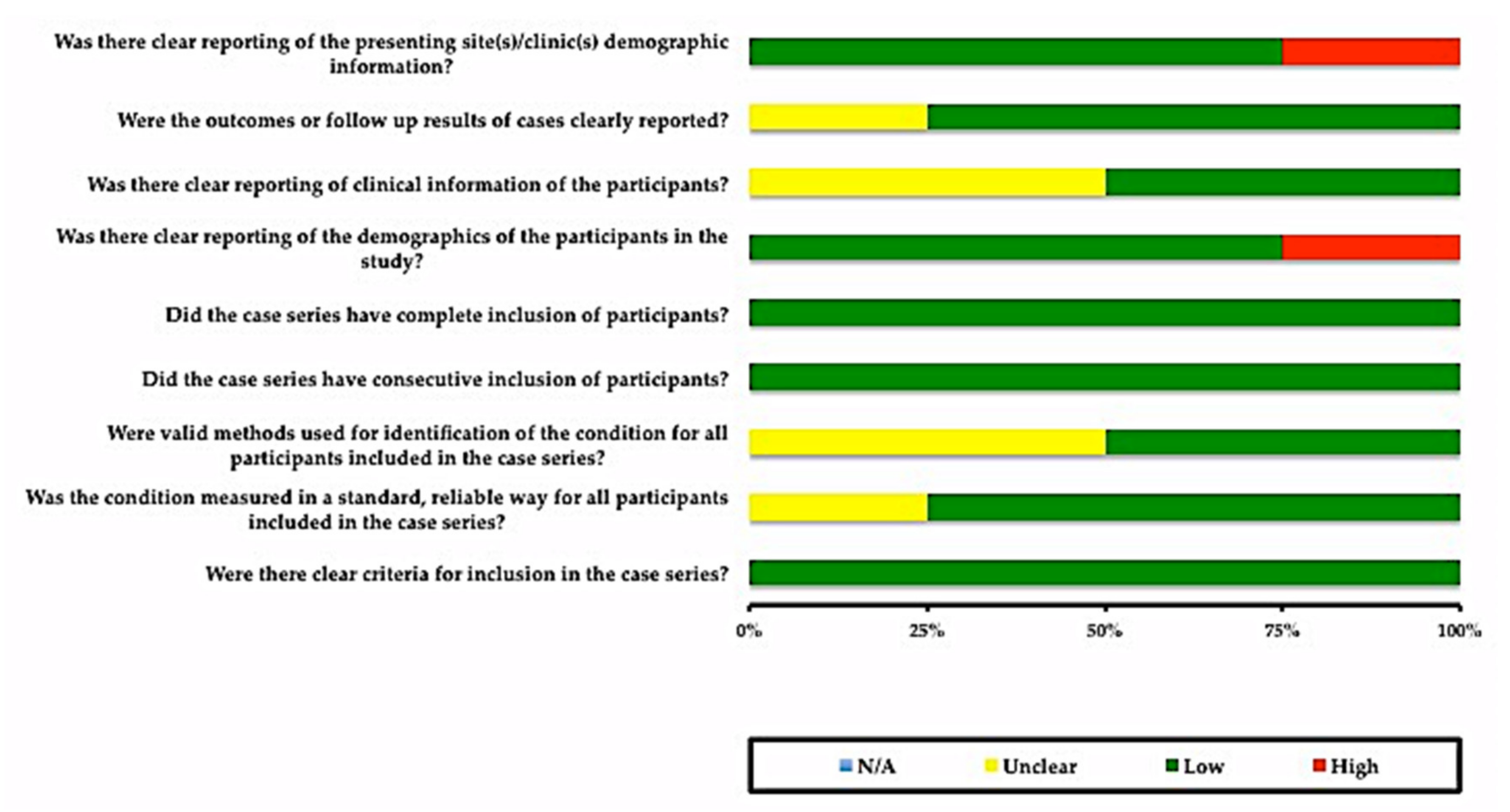
3.3. Risks of Bias in Individual Studies
4. Discussion
5. Conclusions
Author Contributions
Funding
Institutional Review Board Statement
Informed Consent Statement
Data Availability Statement
Conflicts of Interest
References
- Dings, J.P.J.; Merkx, M.A.W.; de Clonie Maclennan-Naphausen, M.T.P.; van de Pol, P.; Maal, T.J.J.; Meijer, G.J. Maxillofacial prosthetic rehabilitation: A survey on the quality of life. J. Prosthet. Dent. 2018, 120, 780–786. [Google Scholar] [CrossRef]
- Atay, A.; Peker, K.; Günay, Y.; Ebrinç, S.; Karayazgan, B.; Uysal, Ö. Assessment of health-related quality of life in Turkish patients with facial prostheses. Health Qual. Life Outcomes 2013, 11, 11. [Google Scholar] [CrossRef] [Green Version]
- De Oliveira, F.M.; Salazar-Gamarra, R.; Öhman, D.; Nannmark, U.; Pecorari, V.; Dib, L.L. Quality of life assessment of patients utilizing orbital implant-supported prostheses. Clin. Implant Dent. Relat. Res. 2018, 20, 438–443. [Google Scholar] [CrossRef]
- Nemli, S.K.; Aydin, C.; Yilmaz, H.; Bal, B.T.; Arici, Y.K. Quality of life of patients with implant-retained maxillofacial prostheses: A prospective and retrospective study. J. Prosthet. Dent. 2013, 109, 44–52. [Google Scholar] [CrossRef]
- Gastaldi, G.; Palumbo, L.; Moreschi, C.; Gherlone, E.F.; Capparé, P. Prosthetic management of patients with oro-maxillo-facial defects: A long-term follow-up retrospective study. J. Oral Implantol. 2017, 10, 276–282. [Google Scholar] [CrossRef]
- Smolarz-Wojnowska, A.; Raithel, F.; Gellrich, N.C.; Klein, C. Quality of implant anchored craniofacial and intraoral prostheses: Patient’s evaluation. J. Craniofac. Surg. 2014, 25, e202–e207. [Google Scholar] [CrossRef] [PubMed]
- Miles, B.A.; Sinn, D.P.; Gion, G.G. Experience with cranial implant-based prosthetic reconstruction. J. Craniofac. Surg. 2006, 17, 889–897. [Google Scholar] [CrossRef] [PubMed]
- Visser, A.; Raghoebar, G.M.; van Oort, R.P.; Vissink, A. Fate of implant-retained craniofacial prostheses: Life span and aftercare. Int. J. Oral Maxillofac. Implants 2008, 23, 89–98. [Google Scholar]
- Abu-Serriah, M.M.; McGowan, D.A.; Moos, K.F.; Bagg, J. Outcome of extra-oral craniofacial endosseous implants. Br. J. Oral Maxillofac. Surg. 2001, 39, 269–275. [Google Scholar] [CrossRef]
- Jacobsson, M.; Tjellstrom, A.; Fine, L.; Andersson, H. A retrospective study of osseointegrated skin-penetrating titanium fixtures used for retaining facial prostheses. Int. J. Oral Maxillofac. Implants 1992, 7, 523–528. [Google Scholar]
- Nishimura, R.D.; Roumanas, E.; Moy, P.K.; Sugai, T.; Freymiller, E.G. Osseointegrated implants and orbital defects: U.C.L.A. experience. J. Prosthet. Dent. 1998, 79, 304–309. [Google Scholar] [CrossRef]
- Toljanic, J.A.; Eckert, S.E.; Roumanas, E.; Beumer, J.; Huryn, J.M.; Zlotolow, I.M.; Reisberg, D.J.; Habakuk, S.W.; Wright, R.F.; Rubenstein, J.E.; et al. Osseointegrated craniofacial implants in the rehabilitation of orbital defects: An update of a retrospective experience in the United States. J. Prosthet. Dent. 2005, 94, 177–182. [Google Scholar] [CrossRef] [PubMed]
- Roumanas, E.D.; Freymiller, E.G.; Chang, T.L.; Aghaloo, T.; Beumer, J., 3rd. Implant-retained prostheses for facial defects: An up to 14-year follow-up report on the survival rates of implants at UCLA. Int. J. Prosthodont. 2002, 15, 325–332. [Google Scholar] [PubMed]
- Zhang, X.; Chen, S.L.; Zhang, J.M.; Chen, J.L. Fabrication of a surgical template for orbital implant placement: A case report. Int. J. Oral Maxillofac. Implants 2010, 25, 826–830. [Google Scholar]
- Buser, D.; Sennerby, L.; De Bruyn, H. Modern implant dentistry based on osseointegration: 50 years of progress, current trends and open questions. Periodontology 2000, 73, 7–21. [Google Scholar] [CrossRef]
- Tahmaseb, A.; Wismeijer, D.; Coucke, W.; Derksen, W. Computer technology applications in surgical implant dentistry: A systematic review. Int. J. Oral Maxillofac. Implants 2014, 29, 25–42. [Google Scholar] [CrossRef] [Green Version]
- Sarment, D.P.; Sukovic, P.; Clinthorne, N. Accuracy of implant placement with a stereolithographic surgical guide. Int. J. Oral Maxillofac. Implants 2003, 18, 571–577. [Google Scholar]
- Tanveer, W.; Ridwan-Pramana, A.; Molinero-Mourelle, P.; Koolstra, J.H.; Forouzanfar, T. Systematic Review of Clinical Applications of CAD/CAM Technology for Craniofacial Implants Placement and Manufacturing of Nasal Prostheses. Int. J. Environ. Res. Public Health 2021, 18, 3756. [Google Scholar] [CrossRef]
- Verma, S.N.; Schow, S.R.; Stone, B.H.; Triplett, R.G. Applications of surgical navigational systems for craniofacial bone-anchored implant placement. Int. J. Oral Maxillofac. Implants 2010, 25, 582–588. [Google Scholar] [PubMed]
- Block, M.S.; Emery, R.W.; Cullum, D.R.; Sheikh, A. Implant Placement Is More Accurate Using Dynamic Navigation. J. Oral Maxillofac. Surg. 2017, 75, 1377–1386. [Google Scholar] [CrossRef]
- D’Haese, J.; Ackhurst, J.; Wismeijer, D.; De Bruyn, H.; Tahmaseb, A. Current state of the art of computer-guided implant surgery. Periodontology 2000, 73, 121–133. [Google Scholar] [CrossRef] [PubMed]
- Moher, D.; Liberati, A.; Tetzlaff, J.; Altman, D.G. Preferred reporting items for systematic reviews and meta-analyses: The PRISMA statement. PLoS Med. 2009, 6, e1000097. [Google Scholar] [CrossRef] [PubMed] [Green Version]
- Moola, S.; Aromataris, E.; Sears, K.; Sfetcu, R.; Currie, M.; Lisy, K.; Qureshi, R.; Mattis, P.; Mu, P. Chapter 7: Systematic reviews of etiology and risk. In Joanna Briggs Institute Reviewer’s Manual; Aromataris, E., Munn, Z., Eds.; JBI: Adelaide, Australia, 2017. [Google Scholar] [CrossRef]
- Li, S.; Xiao, C.; Duan, L.; Fang, C.; Huang, Y.; Wang, L. CT image-based computer-aided system for orbital prosthesis rehabilitation. Med. Biol. Eng. Comput. 2015, 53, 943–950. [Google Scholar] [CrossRef] [PubMed]
- Ciocca, L.; Scotti, R. Oculo-facial rehabilitation after facial cancer removal: Updated CAD/CAM procedures: A pilot study. Prosthet. Orthot. Int. 2014, 38, 505–509. [Google Scholar] [CrossRef]
- Liu, H.; Bai, S.; Yu, X.; Zhao, Y. Combined use of a facial scanner and an intraoral scanner to acquire a digital scan for the fabrication of an orbital prosthesis. J. Prosthet. Dent. 2019, 121, 531–534. [Google Scholar] [CrossRef]
- Yoshioka, F.; Ozawa, S.; Okazaki, S.; Tanaka, Y. Fabrication of an orbital prosthesis using a noncontact three-dimensional digitizer and rapid-prototyping system. J. Prosthodont. 2010, 19, 598–600. [Google Scholar] [CrossRef]
- Sabol, J.V.; Grant, G.T.; Liacouras, P.; Rouse, S. Digital image capture and rapid prototyping of the maxillofacial defect. J. Prosthodont. 2011, 20, 310–314. [Google Scholar] [CrossRef] [PubMed]
- Eo, M.Y.; Cho, Y.J.; Nguyen, T.T.H.; Seo, M.H.; Kim, S.M. Implant-supported orbital prosthesis: A technical innovation of silicone fabrication. Int. J. Implant Dent. 2020, 6, 51. [Google Scholar] [CrossRef]
- Huang, Y.H.; Seelaus, R.; Zhao, L.; Patel, P.K.; Cohen, M. Virtual surgical planning and 3D printing in prosthetic orbital reconstruction with percutaneous implants: A technical case report. Int. Med. Case Rep. J. 2016, 9, 341–345. [Google Scholar] [CrossRef] [Green Version]
- Chiu, M.; Hong, S.C.; Wilson, G. Digital fabrication of orbital prosthesis mold using 3D photography and computer-aided design. Graefe’s Arch. Clin. Exp. Ophthalmol. 2017, 255, 425–426. [Google Scholar] [CrossRef]
- Choi, K.J.; Sajisevi, M.B.; McClennen, J.; Kaylie, D.M. Image-Guided Placement of Osseointegrated Implants for Challenging Auricular, Orbital, and Rhinectomy Defects. Ann. Otol. Rhinol. Laryngol. 2016, 125, 801–807. [Google Scholar] [CrossRef]
- Ciocca, L.; Fantini, M.; Marchetti, C.; Scotti, R.; Monaco, C. Immediate facial rehabilitation in cancer patients using CAD-CAM and rapid prototyping technology: A pilot study. Support Care Cancer 2010, 18, 723–728. [Google Scholar] [CrossRef] [PubMed]
- Verma, S.; Gonzalez, M.; Schow, S.R.; Triplett, R.G. Virtual Preoperative Planning and Intraoperative Navigation in Facial Prosthetic Reconstruction: A Technical Note. Int. J. Oral Maxillofac. Implants 2017, 32, e77–e81. [Google Scholar] [CrossRef] [Green Version]
- Bi, Y.; Wu, S.; Zhao, Y.; Bai, S. A new method for fabricating orbital prosthesis with a CAD/CAM negative mold. J. Prosthet. Dent. 2013, 110, 424–428. [Google Scholar] [CrossRef]
- Weisson, E.H.; Fittipaldi, M.; Concepcion, C.A.; Pelaez, D.; Grace, L.; Tse, D.T. Automated Noncontact Facial Topography Mapping, 3-Dimensional Printing, and Silicone Casting of Orbital Prosthesis. Am. J. Ophthalmol. 2020, 220, 27–36. [Google Scholar] [CrossRef] [PubMed]
- Zhang, X.; Chen, S.; Huang, Y.; Chang, S. Computer-assisted design of orbital implants. Int. J. Oral Maxillofac. Implants 2007, 22, 132–137. [Google Scholar]
- Goh, B.T.; Teoh, K.H. Orbital implant placement using a computer-aided design and manufacturing (CAD/CAM) stereolithographic surgical template protocol. Int. J. Oral Maxillofac. Surg. 2015, 44, 642–648. [Google Scholar] [CrossRef] [PubMed]
- Ewers, R.; Schicho, K.; Truppe, M.; Seemann, R.; Reichwein, A.; Figl, M.; Wagner, A. Computer-aided navigation in dental implantology: 7 years of clinical experience. J. Oral Maxillofac. Surg. 2004, 62, 329–334. [Google Scholar] [CrossRef] [PubMed]
- Mupparapu, M.; Singer, S.R. Implant imaging for the dentist. J. Can. Dent. Assoc. 2004, 70, 32. [Google Scholar] [PubMed]
- Jacobs, R.; Adriansens, A.; Verstreken, K.; Suetens, P.; van Steenberghe, D. Predictability of a three-dimensional planning system for oral implant surgery. Dento Maxillo Fac. Radiol. 1999, 28, 105–111. [Google Scholar] [CrossRef]
- Israelson, H.; Plemons, J.M.; Watkins, P.; Sory, C. Barium-coated surgical stents and computer-assisted tomography in the preoperative assessment of dental implant patients. Int. J. Periodont. Restor. Dent. 1992, 12, 52–61. [Google Scholar]
- Basten, C.H. The use of radiopaque templates for predictable implant placement. Quintessence Int. 1995, 26, 609–612. [Google Scholar]
- Mizrahi, B.; Thunthy, K.H.; Finger, I. Radiographic/surgical template incorporating metal telescopic tubes for accurate implant placement. Pract. Periodont. Aesthet. Dent. 1998, 10, 757–765. [Google Scholar]
- Verstreken, K.; Van Cleynenbreugel, J.; Martens, K.; Marchal, G.; van Steenberghe, D.; Suetens, P. An image-guided planning system for endosseous oral implants. IEEE Trans. Med. Imaging 1998, 17, 842–852. [Google Scholar] [CrossRef] [PubMed]
- Choi, J.-Y.; Choi, J.-H.; Kim, N.-K.; Kim, Y.; Lee, J.-K.; Kim, M.-K.; Lee, J.-H.; Kim, M.-J. Analysis of errors in medical rapid prototyping models. Int. J. Oral Maxillofac. Surg. 2002, 31, 23–32. [Google Scholar] [CrossRef] [PubMed]
- Whyms, B.J.; Vorperian, H.K.; Gentry, L.R.; Schimek, E.M.; Bersu, E.T.; Chung, M.K. The effect of computed tomographic scanner parameters and 3-dimensional volume rendering techniques on the accuracy of linear, angular, and volumetric measurements of the mandible. Oral Surg. Oral Med. Oral Pathol Oral Radiol. 2013, 115, 682–691. [Google Scholar] [CrossRef] [Green Version]
- Taft, R.M.; Kondor, S.; Grant, G.T. Accuracy of rapid prototype models for head and neck reconstruction. J. Prosthet. Dent. 2011, 106, 399–408. [Google Scholar] [CrossRef]
- D’Haese, J.; Van De Velde, T.; Komiyama, A.; Hultin, M.; De Bruyn, H. Accuracy and complications using computer-designed stereolithographic surgical guides for oral rehabilitation by means of dental implants: A review of the literature. Clin. Implant Dent. Relat. Res. 2012, 14, 321–335. [Google Scholar] [CrossRef]
- Alauddin, M.S.; Baharuddin, A.S.; Mohd Ghazali, M.I. The Modern and Digital Transformation of Oral Health Care: A Mini Review. Healthcare 2021, 9, 118. [Google Scholar] [CrossRef] [PubMed]
- Ishida, Y.; Miura, D.; Miyasaka, T.; Shinya, A. Dimensional Accuracy of Dental Casting Patterns Fabricated Using Consumer 3D Printers. Polymers 2020, 12, 2244. [Google Scholar] [CrossRef] [PubMed]
- Dawood, A.; Marti, B.; Sauret-Jackson, V.; Darwood, A. 3D printing in dentistry. Br. Dent. J. 2015, 219, 521–529. [Google Scholar] [CrossRef] [PubMed]
- Stansbury, J.W.; Idacavage, M.J. 3D printing with polymers: Challenges among expanding options and opportunities. Dental materials. Dent. Mater. 2016, 32, 54–64. [Google Scholar] [CrossRef] [PubMed]
- Nayar, S.; Bhuminathan, S.; Bhat, W.M. Rapid prototyping and stereolithography in dentistry. J. Pharm. Bioallied Sci. 2015, 7, 16–19. [Google Scholar] [CrossRef]
- Khorsandi, D.; Fahimipour, A.; Saber, S.S.; Ahmad, A.; De Stephanis, A.A. Fused Deposition Modeling and Stereolithography 3D Bioprinting in Dental Science. EC Dent. Sci. 2019, 18, 110–115. [Google Scholar] [CrossRef]
- Bockey, S.; Berssenbrügge, P.; Dirksen, D.; Wermker, K.; Klein, M.; Runte, C. Computer-aided design of facial prostheses by means of 3D-data acquisition and following symmetry analysis. J. Cranio-Maxillo-Fac. Surg. 2018, 46, 1320–1328. [Google Scholar] [CrossRef] [PubMed]
- Marafon, P.G.; Mattos, B.S.; Sabóia, A.C.; Noritomi, P.Y. Dimensional accuracy of computer-aided design/computer-assisted manufactured orbital prostheses. Int. J. Prosthodont. 2010, 23, 271–276. [Google Scholar] [PubMed]
- Dings, J.P.J.; Verhamme, L.; Maal, T.J.J.; Merkx, M.A.W.; Meijer, G.J. Reliability and accuracy of skin-supported surgical templates for computer-planned craniofacial implant placement, a comparison between surgical templates: With and without bony fixation. J. Cranio-Maxillo-Fac. Surg. 2019, 47, 977–983. [Google Scholar] [CrossRef]


| Publications | No. of Cases | Purpose of Software Planning | Pre-op Data for Digital Planning | Software | Printer/Miller | Printing Materials | Navigation System (Yes/No) | Location & No. of Implants | Implants System |
|---|---|---|---|---|---|---|---|---|---|
| Zhang, X. et al., 2010 [14] | 1 | Surgical template for implants placement | CT | Ease Orbital Implant Planning Software (EOIPlan) (Guangdong Provincial Hospital, First Affiliated Hospital, Sun Yat-sen University, Guangzhou, China) 1 | Rapid prototype; FDM 400mc, Stratasys (Stratasys, Eden Prairie, MN, USA) | NM | No | Orbital bone rim; 3 implants | Vistafix implant system (Entific Medical Systems) |
| Li, S. et al., 2015 [24] | 1 | Simulation for orbital prosthesis and planning for orbital implants | CT | Ease orbital implant planning software (EOIPlan) (Guangdong Provincial Hospital, First Affiliated Hospital, Sun Yat-sen University, Guangzhou, China) 1 | NM | NM | No | Virtual planning | Virtual planning |
| Ciocca, L. et al., 2014 [25] | 1 | Fabrication of Orbital prosthesis substructure and mold | MRI, Laser scan (Desktop NextEngine; NextEngine, Santa Monica, CA, USA) | Freeform Modeling Plus software (3D Systems Inc., Rock Hill, SC, USA) 10 | RP machine (Phantom Desktop Haptic device, ClayTools system; Sensable, Wilmington, MA, USA) | Polyamide resin | No | No implants | No implants |
| Liu, H. et al., 2019 [26] | 1 | Fabrication of mold for orbital prosthesis | 3dMDface System (3dMD LLC, Atlanta, Georgia, USA), 3 shape scanner (3 Shape scanner, Copenhagen, Denmark) | Geomagic studio 2014; (3D Systems Inc., Rock Hill, SC, USA) 2 | 3D printer EOS 500 (EOS, Krailling, Germany) | polyamide (PA2200; EOS) (EOS, Krailling, Germany) | No | No implants | No implants |
| Yoshioka, F. et al., 2010 [27] | 1 | Fabrication of mold | VIVID 910 3D noncontact digitizer (Konica Minolta, Osaka, Japan) | Softwares; Mimics (Mimics Innovation Suite, Materialise, Leuven, Belgium) 5 and Magics, 2 (3D Systems Inc., Rock Hill, SC, USA) | 3D thermojet printer (Z510, Z Corp, Cambridge, MA, USA) | Hybrid plaster: ZP 150, (Z510, Z Corp, Cambridge, MA, USA) | No | No implant | No implant |
| Sabol, J. et al., 2011 [28] | 1 | Fabrication of 3D model for orbital prosthesis | 3dMDface System (3dMD LLC, Atlanta, Georgia, USA) | Magics version 12.01 (3D Systems Inc., Rock Hill, SC, USA) 2 | Zprinter 450 (Z Corp, Cambridge, MA, USA), SLA 7000, a Stereolithography Apparatus (3D Systems, Rock Hill, SC, USA). | zp130 powder (3D Systems Inc., Rock Hill, SC, USA) | No | No implants | No implants |
| Eo, M.Y. et al., 2020 [29] | 1 | Fabrication of master cast | CT scan, Morpheus 3D Scanner® (Morpheus Co., Ltd., Seoul, Korea) | ZBrush® software (Pixologic Inc., Los Angeles, CA, USA) 6 | NM | NM | No | 3 implants in the lateral orbital rim of the zygoma | 4.0-mm-diameter and 7.0-mm-long Luna® implants (Shinhung Co., Seoul, Korea) |
| Huang, Y.H. et al., 2016 [30] | 1 | Surgical template for implants placement, model of patient’s skull | CBCT, Next Generation 17-19, Imaging Sciences International, Hat eld, PA, USA) | Mimics Materialise (Mimics Innovation Suite, Materialise, Leuven, Belgium) 5 | uPrint SE Plus 3D Printer (Stratasys, Eden Prairie, MN, USA), ZPrinter (ZPrinter 310 Plus (Z Corp, Cambridge, MA, USA)) | Acrylonitrile butadiene styrene plastic (ABS) | No | 5 implants (four 3 mm and one 4 mm) in the right orbital rim. (Lateral orbital rim location) | Craniofacial implants (Vista x® Prior Generation, CochlearTM, Sydney, NSW, Australia) |
| Chiu, M. et al., 2017 [31] | 1 | Fabrication of mold | Digital photographs of patient | Autodesk 123D (Autodesk, San Rafael, CA, USA) 9, Digital sculpting software (Z-Brush, Pixologic Inc., Los Angeles, CA, USA) 6 | NM | NM | No | No | No |
| Choi, K.J. et al., 2016 [32] | 1 | Image guided placement of implants by utilizing navigation probe | CT scan | Brainlab (Brainlab AG, Munich, Germany) 7 | No | No | Yes | 2 implants in right superior orbital rim. | Vistafix system (Entific Medical Systems, Goteborg, Sweden) |
| Ciocca, L. et al., 2010 [33] | 1 | Fabrication of mold and substructure | Laser scan; NextEngine Desktop 3D Scanner (NextEngine, Santa Monica, CA, USA) | NextEngine ScanStudio software (NextEngine, Santa Monica, CA, USA) 11, Rapidform XOS software (INUS Technology, Seoul, Korea) 8 | Stratasys 3D printer (Stratasys, Eden Prairie, MN, USA) | Acrylonitrile butadiene styrene plastic (ABS) | No | No | No |
| Verma, S.N. et al., 2017 [34] | 1 | Image guided surgical navigation for orbital implants placement | CT scan | Stryker, Intellect Cranial, (Stryker Navigation system, Kalamazoo, MI, USA) 12 | No | No | Yes | 3 implants in right superior orbital rim. | NM |
| Bi, Y. et al., 2013 [35] | 5 | Fabrication of mold for orbital prosthesis | 3D structured light scanning system (3DSS-STD-II; Digital Manu, Shanghai China) | Geomagic Studio 11.0 (3D Systems Inc., Rock Hill, SC, USA) 2 | Stereo Lithography (SLA) rapid prototyping machine (SPS350; Hengtong Inc, Buffalo, NY, USA) | Resin | No | No implants | No implants |
| Weisson, E.H. et al., 2020 [36] | 3 | Fabrication of mold | Artec Color 3D scanner (Artec 3D, Luxembourg city, Luxembourg), colorimeter (E-Skin by Spectro-Match Ltd., Bath, UK) | Artec Studio 12 Professional (Artec 3D, Luxembourg) 4, Geomagic Studio 12 (3D Systems Inc., Rock Hill, SC, USA) 2 | Ultimaker 3D printer (Ultimaker, Geldermalsen, The Netherlands) | Acrylonitrile butadiene styrene (ABS) | No | No | No |
| Zhang, X. et al., 2007 [37] | 6 | Surgical template for implants placement | CT scan, | Ease Orbital Implant Planning System (EOIPlan) (Guangdong Provincial Hospital, First Affiliated Hospital, Sun Yat-sen University, Guangzhou, China) 1 | Rapid prototype; FDM 400mc, Stratasys (Stratasys, Eden Prairie, MN, USA) | NM | No | 17 implants in total were placed in supraorbital and zygomatic regions | Craniofacial Vistafix implants system (Entific Medical Systems, Goteborg, Sweden) |
| Goh, B.T. 2015 [38] | 4 | Surgical templates for implants placement | CT scan | Simplant Pro CMF module (Dentsply Sirona, York, PA, USA) 3 | Stereolithographic printer (Materialise, Leuven, Belgium) | NM | No | Total of 11 implants were placed in orbital rims of 4 patients. | Vistafix implants (Entific Medical Systems) |
| Assessment | Author and Year | ||||||
|---|---|---|---|---|---|---|---|
| Zhang, X. et al., 2010 [14] | Li, S. et al., 2015 [24] | Ciocca, L. et al., 2014 [25] | Liu, H. et al., 2019 [26] | Yoshioka, F. et al., 2010 [27] | Sabol, J. et al., 2011 [28] | Eo, M.Y. et al., 2020 [29] | |
| Were patient’s demographic characteristics clearly described? | Yes | Yes | Yes | Yes | Yes | Yes | Yes |
| Was the patient’s history clearly described and presented as a timeline? | Yes | No | No | No | Yes | Yes | Yes |
| Was the current clinical condition of the patient on presentation clearly described? | Yes | Yes | Yes | Yes | Yes | Yes | Yes |
| Were diagnostic tests or assessment methods and the results clearly described? | No | No | No | No | No | No | Unclear |
| Was the intervention(s) or treatment procedure(s) clearly described? | Yes | Yes | Yes | Yes | Yes | Yes | Yes |
| Was the post-intervention clinical condition clearly described? | Yes | Yes | Yes | Yes | Yes | Yes | Yes |
| Were adverse events (harms) or unanticipated events identified and described? | No | No | No | No | No | Yes | No |
| Does the case report provide takeaway lessons? | Yes | Yes | Yes | Yes | Yes | Yes | Yes |
| Overall appraisal | Included | Included | Included | Included | Included | Included | Included |
| Huang, Y.H. et al., 2016 [30] | Chiu, M. et al., 2017 [31] | Choi, K.J. et al., 2016 [32] | Ciocca, L. et al., 2010 [33] | Verma, S. N. et al., 2017 [34] | |||
| Were patient’s demographic characteristics clearly described? | Yes | Yes | Yes | Yes | Yes | ||
| Was the patient’s history clearly described and presented as a timeline? | Yes | Yes | Yes | Yes | No | ||
| Was the current clinical condition of the patient on presentation clearly described? | Yes | Yes | Yes | Yes | Yes | ||
| Were diagnostic tests or assessment methods and the results clearly described? | No | No | No | Unclear | No | ||
| Was the intervention(s) or treatment procedure(s) clearly described? | Yes | Yes | Yes | Yes | Yes | ||
| Was the post-intervention clinical condition clearly described? | Yes | Yes | Yes | Yes | Yes | ||
| Were adverse events (harms) or unanticipated events identified and described? | No | No | Yes | No | No | ||
| Does the case report provide takeaway lessons? | Yes | Yes | Yes | No | Yes | ||
| Overall appraisal | Included | Included | Included | Included | Included | ||
| Assessment | Author and Year | |||
|---|---|---|---|---|
| Bi, Y. et al., 2013 [35] | Weisson, E.H. et al., 2020 [36] | Zhang, X. et al., 2007 [37] | Goh, B.T. 2015 [38] | |
| Were there clear criteria for inclusion in the case series? | Yes | Yes | Yes | Yes |
| Was the condition measured in a standard, reliable way for all participants included in the case series? | Yes | Unclear | Yes | Yes |
| Were valid methods used for identification of the condition for all participants included in the case series? | Unclear | Yes | Unclear | Yes |
| Did the case series have consecutive inclusion of participants? | Yes | Yes | Yes | Yes |
| Did the case series have complete inclusion of participants? | Yes | Yes | Yes | Yes |
| Was there clear reporting of the demographics of the participants in the study? | Yes | Yes | Yes | Yes |
| Was there clear reporting of clinical information of the participants? | Unclear | Yes | Unclear | Yes |
| Were the outcomes or follow up results of cases clearly reported? | Yes | Yes | Unclear | Yes |
| Was there clear reporting of the presenting site(s)/clinic(s) demographic information? | Yes | Yes | Yes | Yes |
| Overall appraisal | Included | Included | Included | Included |
| Stereolithography (SLA) | Fused Deposition Modeling (FDM) | |
|---|---|---|
| Materials for printing | Resins | Acrylonitrile Butyro Styrene (ABS) Calcium phosphate based material Polycarbonates Polyphenylsulfones Nylon |
| Advantages | Short working time High product resolution No deformation More efficient for complex models | Relatively cheaper Post-processing no chemicals |
| Disadvantages | Limited mechanical strength (mechanical strength depends on the viscosity of resin used) Irritant Relatively expensive | Long working time Low product resolution Limited shape complexity Gradual deformation |
| Thickness of layer | 0.05–0.015 mm | 0.5–0.127 mm |
| Possible applications for facial prosthesis fabrication | Surgical templates for computer guided surgeries Retentive substructures | Models after surface scans Molds Wax-ups Provisional prosthesis |
| Included Articles | Outcome | Recommendations | Limitations |
|---|---|---|---|
| Zhang, X. et al., 2010 [14] | According to the authors, the digital surgical template was precisely designed for specific surface topography or orbital bone, therefore the template was extremely stable and no external fixation was required. | Magnetic retention was recommended for orbital prosthesis due to the ease of placement and removal without compromising retention of prosthesis. | - |
| Li, S. et al., 2015 [24] | The biggest measurement error was less than 0.3 mm and the variance was less than 0.03. The system provided the simulated rehabilitation images, which were helpful in preoperative planning. | According to surgical team this error was claimed to be acceptable and satisfies the clinical requirements regarding orbital implants placement. | - |
| Ciocca, L. et al., 2014 [25] | Through this technique it was possible to reduce the thickness (≤1 mm) within 1.5 cm area along the margins with progressive increase in thickness in bulk area of silicone. Furthermore, this technique enabled the connection of eyeglasses and prosthesis with the help of digitally designed substructure, which enhanced the retention. | - | According to the authors, the availability of CAD skilled technician can be limited. Furthermore, Closure of oculo-facial defect by the help of myocutaneous flap could be a prosthetic limitation due to the degree of difficulty in adapting the thin margins of prosthesis to mobile surface of flap during the movement of cheek. |
| Liu, H. et al., 2019 [26] | This technique saved time and labor compared with conventional method. | The use of intraoral scanner can reproduce skin surface texture therefore authors claimed that additional manual sculpturing is not necessary. | The used technique is applicable to unilateral orbital defects. |
| Yoshioka, F. et al., 2010 [27] | The photo mapping function of mimics enabled confirmation of the external profile and position of pupil on designed model, which was not possible to locate accurately through CT scan or convectional impression as patient need to close the eyes. | This report presented non-contact laser scanning method, which was clammed to be safer than CT scan as the patient will not be exposed to unnecessary radiation dose | |
| Sabol, J. et al., 2011 [28] | 3D photography technique provided an STL model and 3D printed model for fabrication of orbital prosthesis. There were no ultimate differences in the fit of orbital prostheses fabricated on these models. | Authors recommended the fabrication of intraoral prosthesis before the orbital prosthesis, as the contours of skin should be stable before capturing the image. | The limitations stated were the high cost of CAD/CAM systems and inability to match the color with adjacent skin. |
| Eo, M.Y. et al., 2020 [29] | The combination of 3D scanning with digital planning and reconstruction resulted in accurate orbital prosthesis in short time. The patient had reported excellent satisfaction for esthetics and stability of orbital prosthesis. The ability to reproduce major mold resulted in accurate silicone morphology. | - | Authors highlighted the limitation of silicone bonding with metal components, using plastic clay resin. |
| Huang, Y.H. et al., 2016 [30] | The surgical guide obtained after digital planning was found to resist any movement upon seating, which indicated accurate fitting between the bone and surgical guide. Furthermore, surgical guide reduced the operating time. | - | According to the authors, time and cost spent for designing and production of surgical template was favorable but more detailed time and cost comparison will give better understanding of cost effectiveness of surgical templates. |
| Chiu, M. et al., 2017 [31] | The presented technique utilized digital camera instead of CT/MRI, which reduced the cost of data acquisition | 3D photography was recommended in place of CT scans as it reduced the unnecessary radiation dose exposure and gives color images which are important for maxillofacial prosthesis | The limitations expressed by authors were the need of specialized skills and the cost of digital printers, which might not be available in rural location. Furthermore, it was highlighted that 3D printing of medical grade silicone is not available |
| Choi, K.J. et al., 2016 [32] | Image guided system was used for 3 cases. In patients 1 and 2, implants were real time guided even after extensive soft tissue debridement. For patient 3, alternative implant site with adequate amount of bone was successfully identified and implant was guided in place through image-guided system. | Authors suggested indications of image guided implants placement in head and neck cancer patients, which present altered anatomy, inadequate amount of bone and prior free flap reconstruction. | - |
| Ciocca, L. et al., 2010 [33] | The CAD/CAM technique along with “Ear & Nose Library” dictated the fabrication of provisional orbital prosthesis, which helped in immediate recovery following ablative cancer surgery and improved the quality of life of patient. | Immediate recovery from this provisional prosthesis is useful after ablative surgery. Titanium framework was recommended to support the facial prosthesis instead of ABS framework to reduce the bulk and improve the rigidity of attachment. | - |
| Verma, S.N. et al., 2017 [34] | This technique saved approximately 12 h of laboratory time, which is normally spent on designing surgical template. Eliminated two clinical preoperative visits of patient. The virtual planning allowed the surgeon to plan the incision and implant emergence site according to prosthetic boundaries. | While treating the unilateral defect, the implants location and prosthetic design are decided on the basis of mirrored image data from non-affected side. Therefore with all virtual planning, preoperative impression is not required. | Limitation of this specific technique was the inability to estimate the trajectory of registered drill in contra-angle hand-piece during implants osteotomy when utilizing this navigation platform. As the contra-angle hand-piece might be needed in anatomical location with limited space such as while orbital implants placement. |
| Bi, Y. et al., 2013 [35] | The ocular defect was accurately restored. The structure of eyelid and the wrinkles were clear. The size, marginal adaptation and contour were acceptable. The digital planning and designing saved the time and reduced the visits of patients. | Following silicone vulcanization, the lower pieces of mold should be separated first, and ocular resin models should be carefully removed from prosthesis after they separate from upper pieces of mold. This sequence will prevent damage to silicone prosthesis. | - |
| Weisson, E.H. et al., 2020 [36] | The data set allowed fast and accurate sculpturing to refine the prosthesis edge-skin interface without the need of patient physically present. | This technique reduces the cost and fabrication time of prosthesis in the case, if it is damaged or lost. | The 3D printer utilized in this study took 20 h to print the mold, which according to authors, can be reduced by industrial type 3D printers. |
| Zhang, X. et al., 2007 [37] | The implants were successfully and precisely placed according to digital planning. No complications were encountered. Surgical time had reduced as compared to conventional methods. Orbital prosthesis had fit over the implants and patients were satisfied from final outcome. | Improvement in software is needed, to enable mirroring of healthy eye on the defect side, which is important for orientation during planning. | The number of cases was too small for statistical analysis to check the accuracy of this system. |
| Goh, B.T. 2015 [38] | The stereolithographic surgical template served to transfer individualized plan to operating room for orbital implants placement. During surgery, templates fitted well on orbital rim. There was no need to shift the implant position from originally planned position. Surgery was more predictable and less dependent on surgical skills. | Magnetic retention was recommended as it offers adequate retention, ease of orbital prosthesis placement and better access for hygiene maintenance. | According to authors, long-term survival of implants in orbital defect area was unpredictable due to poor bone quality and radiation dose. |
| Weisson, E.H. et al., 2020 [36] | Bi, Y. et al., 2013 [35] | ||
|---|---|---|---|
| Procedures | Estimated Time (hour) | Procedures | Estimated Time (hour) |
| Facial topography mapping | 1 h | Data acquisition | 5 h |
| Digital design and printing of mold | 26 h | Fabrication of prosthesis | |
| Manufacturing of prosthesis | 17 h | Finishing and delivery | |
| Finishing and delivery | 2 h | Digital design and fabrication | 13.5 h |
| Total time | 46 h | Total time | 18.5 h |
| Publications | Purpose of Software Planning | Pre-Op Data for Digital Planning | Software | Printer/Miller | Printing Materials | Outcome | Limitations |
|---|---|---|---|---|---|---|---|
| Bockey, S. et al., 2018 [56] | To Assess, if the method of digital designing of orbital models for orbital prostheses is suitable for patients? Comparison was made among 4 groups; mirror eye, CAD prosthesis, cut out defect area and manually designed prosthesis | 3D surface scans of 32 patients were captured through fringe projection method. Measuring accuracy of high resolution is 0.3 mm | 3D software; pVision3D, Rhinoceros (Robert McNeel & Associates, version 4.0) | 3D printer (OBJET EDEN 260V, Stratasys Ltd., Eden Prairie, USA). With accuracy of 600 dpi lateral and 1600 dpi axial. | VeroDent MED-670 and VeroDent Plus MED-690. | Mirrored eye had the lowest asymmetry index (AI) while the manually designed orbital prosthesis had highest asymmetry index. The deviation of mean values between these groups was 0.33. The results indicated that the use of this technique can help to increase the facial symmetry of prosthesis and can further assist Anaplastologists in technical procedures, as the mirrored eye is the direct template of prosthesis, which could be adjusted manually. | In this study, the question of appropriate implant location and subsequent reconstruction heights were not included. It was not possible to record the position of abutments due to undercuts. Furthermore, this method of reconstruction is only suitable for paired structures, such as eyes, ears. |
| Marafon, P.G. et al., 2010 [57] | To determine the dimensional accuracy of orbital prostheses manufactured through CAD/CAM system by utilizing CT scan. | CT scan | InVesalius Software (CTI-Information Technology Center), Magics Software (Magics X SP2 v.1.1.17, Materialise), Rhinoceros Software v. 4.0 (Robert McNeel & Associates), SolidWorks Software v. 2008 (Dassault Systèmes) | Selective laser sintering (SLA) (Sinterstation 2000, 3D Systems) | Polyamide (Robotec) | There was no significant difference between the position of landmarks on the prosthesis and the landmarks on the face, indicating no significant displacement of orbital prosthesis in transverse or oblique directions. Furthermore no significant difference between the measurements of the cast and on the orbital prosthesis, thus indicating that the dimensions of orbital prosthesis were stable in transverse, oblique and vertical directions. The dimensional accuracy of orbital prosthesis suggested that CAD/CAM system maybe suitable for clinical use. | - |
| Dings, J.P.J. et al., 2019 [58] | To determine the accuracy of guided implants placement by using CAD/CAM system to design skin supported digital surgical template | CBCT | Maxilim software (Medicim NV, Mechelen, Belgium), Procera System (NobelGuide; Nobel Biocare, Goteborg, Sweden) | NM | Biocompatible resin | One hundred and thirty-six craniofacial Branemark MK III implants were placed in 10 cadaver heads. Out of total 136 implants, 57 implants were placed in orbital region. The use of fixation pins showed higher mean deviation at implants shoulder, angle and depth when compared to non-fixated surgical templates. Surgical templates without fixation pins showed non-significant difference in angular deviation. | All cadaver heads were edentulous therefore there were no ideal fixed reference points to design the hard tissue supported surgical templates. |
Publisher’s Note: MDPI stays neutral with regard to jurisdictional claims in published maps and institutional affiliations. |
© 2021 by the authors. Licensee MDPI, Basel, Switzerland. This article is an open access article distributed under the terms and conditions of the Creative Commons Attribution (CC BY) license (https://creativecommons.org/licenses/by/4.0/).
Share and Cite
Tanveer, W.; Ridwan-Pramana, A.; Molinero-Mourelle, P.; Forouzanfar, T. Systematic Review of Clinical Applications of CAD/CAM Technology for Craniofacial Implants Placement and Manufacturing of Orbital Prostheses. Int. J. Environ. Res. Public Health 2021, 18, 11349. https://doi.org/10.3390/ijerph182111349
Tanveer W, Ridwan-Pramana A, Molinero-Mourelle P, Forouzanfar T. Systematic Review of Clinical Applications of CAD/CAM Technology for Craniofacial Implants Placement and Manufacturing of Orbital Prostheses. International Journal of Environmental Research and Public Health. 2021; 18(21):11349. https://doi.org/10.3390/ijerph182111349
Chicago/Turabian StyleTanveer, Waqas, Angela Ridwan-Pramana, Pedro Molinero-Mourelle, and Tymour Forouzanfar. 2021. "Systematic Review of Clinical Applications of CAD/CAM Technology for Craniofacial Implants Placement and Manufacturing of Orbital Prostheses" International Journal of Environmental Research and Public Health 18, no. 21: 11349. https://doi.org/10.3390/ijerph182111349
APA StyleTanveer, W., Ridwan-Pramana, A., Molinero-Mourelle, P., & Forouzanfar, T. (2021). Systematic Review of Clinical Applications of CAD/CAM Technology for Craniofacial Implants Placement and Manufacturing of Orbital Prostheses. International Journal of Environmental Research and Public Health, 18(21), 11349. https://doi.org/10.3390/ijerph182111349