
Design of a Rotary Transformer for Installations on Large Shafts
by
 , , , and
Nicola Toscani
1,* ,
,
Massimo Brunetti
2,
Maria Stefania Carmeli
1,
Francesco Castelli Dezza
1 and
Marco Mauri
1 1
Politecnico di Milano, via La Masa 1, 20156 Milano, Italy
2
Leonardo Helicopters, via Giovanni Agusta 520, 21017 Cascina Costa, Italy
*
Author to whom correspondence should be addressed.
Appl. Sci. 2022, 12(6), 2932; https://doi.org/10.3390/app12062932
Submission received: 31 December 2021
/
Revised: 18 February 2022
/
Accepted: 10 March 2022
/
Published: 13 March 2022
(This article belongs to the Special Issue Designs, Analysis and Control for Electrical Machines)
Abstract
:Rotary transformers are adopted to transfer energy from primary to secondary in situations in which the two sides are in relative rotation. These devices are cylindrical transformers with two cores and the corresponding winding separated by an air gap. Their employment became quite convenient with the availability of power electronics, allowing the operation of electrical systems at relatively high frequencies. In particular, this paper proposes the design of a light and efficient transformer which can be used in applications involving large shafts. Moreover, a sliced arrangement for the magnetic core is proposed together with the experimental validation of this solution on a reduced-size prototype.
1. Introduction
Transformers are electrical machines that allow us to transfer power between two different parts of a circuit. Their more common application is in the field of power systems and electrical transmission and distribution, since they can ensure galvanic insulation between the windings and they allow us to change voltage and current levels between the two sides of the circuit. In the last decades, new applications arose due to the spread of power electronics. In particular, the possibility to push the operational frequency up to hundreds or thousands Hz allowed the exploitation of magnetic cores which are far smaller than the corresponding counterparts working at 50 or 60 (see [1]) as well as enable their exploitation on electronics systems and printed circuit boards. Among these new applications, rotary transformers [2,3], allow power flow between parts of the systems which are in relative rotation. Since this energy transfer is obtained by splitting the core in two by inserting an air gap, no brushes or sliprings are required. Therefore, such systems allow the so-called wireless power transfer, which can be achieved also using a capacitive coupling as shown in [4]. There are some examples of application of wireless power transfer based on inductive coupling in rotating electrical machines. Indeed, sliprings can be substituted by rotary transformers in wound rotor induction machines (see [5,6,7]) as well as in synchronous ones (see [8]). In particular, this paper focuses on the design of a rotary transformer suited for installations on large shafts, which are typical of automotive [9], railway [10], naval, aerospace [11,12], or some industrial applications. The goal of this work is to provide some guidelines for the design of efficient rotary transformers working in such environments. Therefore, the main focus of the steps proposed here in the following is to reduce the weight of the device and to keep its radial size (with respect to shaft diameter) as small as possible. Indeed, an excess of inertia may jeopardize the performance of the system in which the transformer operates (e.g., an electrical machine, a train, an aircraft, etc.). To this aim, two multi-objective optimizations (similar to [13]) were performed. The first is based on a brute-force grid search algorithm, which is needed to start approaching the optimal result by exploring the available solutions. Then, this search was refined using a genetic optimization [14], which is a generalization of the single-objective procedure proposed in [5]. The goal is to obtain a compact, efficient and light device that allows a power transfer of about 4 from primary to secondary according to the application presented in [11,12]. After that, a further weight reduction was obtained by slicing the magnetic core, similar to what is reported in [15]. This operation is a consequence of the higher fragility of bulk cores with respect to split cores, in particular if ferrite or sintered materials are adopted. Since this procedure may seem quite odd and, apparently, might compromise the coupling between the primary and secondary, an experimental validation performed on a reduced-scale prototype is presented. This small-size device was realized following the same steps reported in this paper, allowing us to keep the realization costs limited. However, these tests were aimed at verifying that both the design approach and the developed models allow us to predict the resulting performances of the device in an accurate way. These two points are of paramount importance in view of tailoring this proposed design to a specific application. Therefore, the paper is organized as follows: Starting from a general overview of the device and its equivalent circuits, the study goes on with an analytical investigation of the input impedance of the rotary transformer, which is of paramount importance if some reactive power compensation strategies should be included in the system to improve both the active power transfer and system efficiency (see Section 2). Then, Section 3 briefly presents the electromagnetic finite-elements simulation environments that were adopted for studying and optimizing the device. The design and the performed optimizations are described in detail in Section 4. Then, the experimental validation of this design approach based on a reduced-scale prototype is proposed in Section 5. Finally, conclusions are reported in Section 6.
2. Rotary Transformer: Model and Parameters
Different from power transformers installed in power plants or stations [16,17], primary and secondary windings in rotary transformers do not share the same magnetic core. Indeed, two cores are required to allow relative movement between the two parts of the system. As a consequence, each winding is wound around the corresponding core. Due to the particular structure of this device, the flux should cross the air gap at least twice to close the magnetic path. The presence of any air gap is not foreseen in transformers installed in power plants (which do not allow any relative movement between primary and secondary due to their static application [18]) and it strongly impacts on the magnetic characteristics of the device. On one hand, this contributes to linearizing the behaviour of the core, but, on the other hand, the magnetic coupling drops dramatically with respect to transformers with a bulk core. As a matter of fact, the magnetic flux leakage is much higher than static, single-core solutions. Among the possible topologies which are available in the literature for rotary transformers [13,19], the co-axial topology was selected (see Figure 1) because it allows for an easy installation and it ensures robustness from a magnetic coupling point of view. Indeed, the power transfer proves to be less sensible to misalignment and eccentricity than other arrangements. It can be noted that the literature typically reports primary on the outermost part of the structure and secondary on the innermost part. Actually, this choice depends only on the particular configuration of the considered system, and nothing prevents the system from adopting the arrangement proposed in Figure 1.
2.1. Equivalent Circuits
In view of the analysis with electromagnetic finite elements (FEM) software, an equivalent circuit based on a mutual inductor was considered (see Figure 2). This explains why the extraction of the parameters of the equivalent circuit, , and M, is simpler in an FEM environment. and are the self-inductances of the two windings, whereas M stands for the mutual parameters between them.
It can be noted that , and M allow for the evaluation of the magnetic coupling coefficient between the two windings as well as the leakage and magnetizing inductances (referring to an approximate -equivalent circuit for power transformers, see [16,20]) as follows:
Based on the equivalent circuit reported in Figure 2, the resistances and model the resistance of the copper for both windings. Therefore, the equations that model this two-port system are the following:
This mathematical representation of the system allows us to determine some useful analytical expressions. In particular, it can be assumed that the secondary is connected to a load resistance (such as in de-icing applications, see [11,12]) and the input impedance seen from the primary terminals can be determined. To this aim, it is useful to consider the phasor domain (see Figure 3) to provide an expression of , which is frequency-dependent, as well.
The solution of this circuit allows us to state that:
where is the pulsation corresponding to the considered harmonic at frequency f. By splitting the real and the imaginary parts of this impedance, it is possible to identify and , which are both frequency-dependent:
2.2. Compensation Strategy
It can be stated that the source sees an impedance which is, in general, complex, from Equations (6) and (7). Therefore, a significant amount of the input power is related to the nonzero imaginary part of . This reactive nature of the impedance does not cause any increase in the active power transfer, but it raises the absolute value of the absorbed current and therefore the ohmic losses (), leading to a drop in the efficiency of the system . To eliminate and to increase , it is possible to design the transformer as:
which is not so simple to obtain in practice, since this equation is frequency-dependent and it has three degrees of freedom (, and M). Moreover, this equation may lead to mathematical solutions that correspond to unfeasible conditions (i.e., values of , and M may be such that ) and they must be discarded. Alternatively, it can be thought to insert some capacitors which can resonate with the coils to provide a compensation of for a specified frequency f. In the literature, many solutions are available involving two capacitors connected in series and/or in parallel with respect to each winding, as can be seen in [21,22,23,24,25]. In this work, two solutions involving one or two series capacitors [26] were selected. They are represented in Figure 4a,b. These capacitors were tuned in such a way to cancel out the imaginary part of the corresponding input impedance. To this aim, the new expressions of are considered here:
where and stand for the input impedance for the single- and double-capacitor configurations, respectively. Therefore, for the single-capacitor case, the strategy is to tune so that the whole imaginary part simplifies:
and the input impedance of this configuration becomes purely real and equal to (6). Notably, the capacitor does not affect the real part of the input impedance (only the imaginary), so the active input power associated with the fundamental frequency is increased:
The single-capacitor configuration is thus beneficial both to the system efficiency and effectiveness. On the other hand, the tuning procedure for the double-capacitor configuration has, in principle, an infinite number of solutions, being one equation with two unknowns. As a matter of fact, the imaginary part to be zeroed can be expressed as follows:
A smart way to solve this critical point is to focus back on Equation (10); it can be seen that and can be tuned according to and , respectively, that is:
allowing us to obtain a purely real input impedance equal to:
This choice allows for an easy tuning of the capacitors, which are less subjected to variations of transformer parameters due to aging, temperature drifts and peculiar working conditions with respect to the other single- or double-capacitor options. Moreover, each capacitor is bouncing energy with the winding on the same side only. Otherwise, the compensation strategy foresees the flow of some energy between and or between and . On the other hand, it must be observed that compensation with two capacitors does not necessarily imply that the active power increases with respect to the other cases with no capacitor or one capacitor only. It is recommended to study the input impedance in an accurate way before choosing any compensation strategy.
2.3. Power Electronics
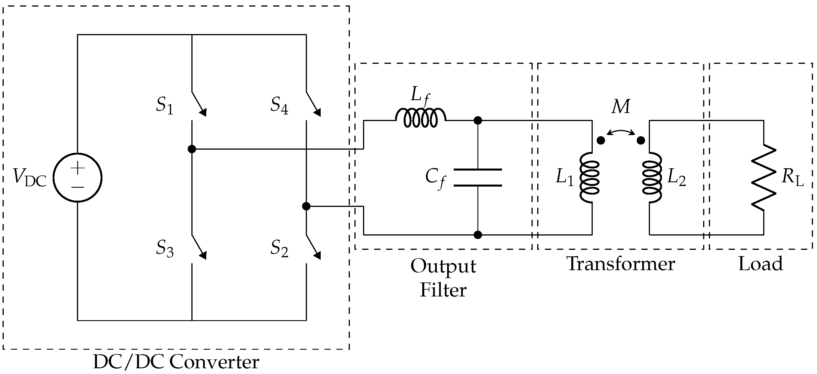
Finally, another equivalent circuit including the converter topology that should be adopted for supplying the rotary transformer is considered in the following. Referring to Figure 5, it can be noted that the reported topology of the converter is full-bridge, but the technology of the single switch (, , and ) is not specified. Indeed, they can be IGBTs or MOSFETs, depending on the voltages and currents required for the applications as well as the chosen switching frequency . A simple ideal DC source is connected in input to the converter, whereas an output filter is interposed between the power electronics and the transformer. It can be noted that and are required only in case a particular harmonic content needs to be achieved on the output.
Assuming connection the power electronics to a DC line, the converter should be able to supply the transformer with a pulsed-width-modulated waveform or a square wave with period . The value of should be chosen carefully to avoid any interference with other equipment installed onboard.
3. Finite-Elements Analysis
Electromagnetic analyses with finite-elements software were set in view of the optimization of the transformer design. Both 2D and 3D runs were needed. In particular, 2D analyses were performed with the free FEMM software and they allowed preliminary investigations on the device for checking its performance as well as the sizing of its magnetic core. Furthermore, 3D analyses were carried out in ANSYS Maxwell to verify the results of the preliminary analyses and to investigate possible solutions aimed at weight reduction. In both cases, the core was supposed to be made of ferrite with relative permeability and a density of . Moreover, it was observed that commercial ferrites with similar characteristics saturate for magnetic flux density equal to . Furthermore, the coils were realized in copper with a pessimistic filling factor .
3.1. Two-Dimensional Analyses
The preliminary planar finite-element analyses were intended to check the capability of the structure based on realistic geometrical dimensions and on the adopted materials. The goal was to obtain a device able to transmit a power in the order of 4 from primary to secondary; this solution can be used to feed electric or electronic equipment for both signal or power applications. For example, a rotary transformer such as this can be used for de-icing purposes on tail-rotors on helicopters, as shown in [11,12], or to supply rotors in medium-size wound induction motors as well as synchronous machines (see [5,6,7,8]). The switching frequency at which the transformer should operate was set in the order of 10– to allow the use of industrial components and to avoid radiated emissions. Moreover, the converter was assumed to work in square-wave modulation, allowing us to obtain a first harmonic with peak value (Figure 5). As a consequence, ferrite was chosen as the material for the core to limit eddy-current and hysteresis losses as much as possible. Then, its geometrical dimensions were roughly estimated based on the available space. For example, the inner radius of the core should be around 90 , whereas its height can range between 20 and 30 . To this aim, FEMM was exploited in view of the optimization of the core, since its files can be called, generated, edited and executed from MATLAB®. Due to the coupling of the two aforementioned softwares, it was possible to estimate the parameters , and M of the rotary transformer, computing the flux linkage in FEMM for the two windings while supplying them one at a time. Then, the values of the parameter were used in MATLAB® to solve the equivalent circuit reported in Figure 3 (a supply voltage of was assumed, which could be obtained using a rectifier on a monophase system) and inject the computed currents and back into each corresponding wire in FEMM in a new simulation to check the saturation of the magnetic core. An example of the output of one of these analyses is reported in Figure 6. The problem was set to be axisymmetric, i.e., the drawn section was considered to be perfectly symmetrical over a rotation of 360° with respect to the shaft.
These preliminary investigations were all static, that is, without simulating the spin of the transformer. However, they prove that a structure with an air gap of 1 is capable of transferring power in the range 1– 6 (depending on the cross section of the magnetic circuit and on the number of turns of the coils) from primary to secondary without saturating the magnetic core.
3.2. Three-Dimensional Analyses
Electromagnetic 3D simulations were carried out in ANSYS Maxwell, as well, to check the results obtained with 2D analysis. Since the structure was highly symmetrical, it was possible to cut the 3D model of the rotary transformer into a small slice to obtain simpler and faster simulations. Indeed, it was possible to define symmetry planes to mirror the structure of the device on the plane normal to the axis of rotation. In addition, master and slave planes were used to repeat the considered slice periodically around the rotational axis. An example on the exploitation of symmetry planes is reported in Figure 7.
This strategy worked only to the limit of a section of a plane (2D) repeated over all 360°, likewise an axisymmetric FEMM analysis. In light of this consideration, the 3D simulations may appear completely useless for this kind of device, since they may be seen as a re-run of a simpler simulation which is already available. However, 3D simulations allow us to perform virtual tests with rotating parts as well as to include fringing effects in an accurate way, which effects play a key role during the optimization of the magnetic core aimed at weight reduction.
4. Design of the Transformer
After the preliminary numerical finite-element investigations, the optimization of the size of the core was performed. The goal was to obtain the required power transfer from the primary to secondary, trying to exploit the magnetic core as much as possible, within the magnetic/thermal limits of the considered materials and minimizing the weight of the device’s active parts. To simplify the procedure, the optimization was split into three different steps: First, a brute-force grid-search optimization was performed to investigate many different geometrical configurations of the core and to identify the most promising. Then, a genetic algorithm was performed, starting from the latter, to refine the winding arrangement. Finally, a further weight reduction was achieved by removing some parts of the magnetic core and investigating their impact on the power transfer by 3D simulation. In all these runs, a conservative limit of was set for the magnetic flux density inside the core, which is well below the saturation limit of the ferrite, so as to avoid the risk of transformer overrating. Actually, a cautious threshold was required, since the analyses in FEMM were performed at the fundamental frequency only. For similar reasons, a maximum current density of was considered, in conjunction with a load resistance of 20 . For a fixed slot area, Joule losses are proportional to the square of the current density:
Therefore, the combination of a relatively low current density along with favourable air conditions (such as those of a typical helicopter de-icing application [11,12]) should avoid the risk of transformer overheating. The device was supplied with a sinusoidal voltage that had a peak value of and . Namely, the first harmonic of a square wave with amplitude 270 (which is equal to the DC bus voltage, as well) was considered. In principle, thermal analyses should be carried out, as well, during the design of the transformer (as reported in [27]); however, since no peculiar application was considered, the current density constraint should limit the Joule losses and therefore prevent overheating. It should be underlined that compensation through resonant capacitors was not considered during this early design stage.
4.1. Grid-Search Optimization
This first process aimed to study the behaviour for a large number of feasible geometrical configurations and to get as close as possible to the optimal result. Indeed, many combinations of the variables reported in Figure 8 should be analysed.
To keep the execution time of the algorithm reasonably low, some constraints were introduced as follows:
- the air gap between the two cores was set to ;
- the radius of the shaft was set to ;
- the height of the core was set to .
Moreover, the two winding slots were considered identical, i.e., . Regarding the electrical part of the system, the numbers of turns of the coils and were set to be equal, , as well, whereas the transferred power on the secondary side of the transformer was constrained to be at least 2 . In light of these indications, the degrees of freedom of this study were the number of turns N, the width of the winding slot and the thicknesses of the core in different points of the structure , and . In addition, Litz wires were considered in the very first stages of the design of the rotary transformer, assuming a cross section of for each conductor and a pessimistic filling factor equal to 0.4; thus, this optimization included the same variable for both windings. It can be noted that these widths can be constrained based on the geometrical structure of the device and the number of conductors in each slot so that only variations in , N and are considered. Therefore, the following ranges of variation were exploited for this first optimization:
- , step between consecutive samples equal to ;
- , step between consecutive samples equal to 5;
- , step between consecutive samples equal to 1.
In detail, the grid-search foresaw the variation of the geometrical parameters in the aforementioned pre-determined samples at the beginning of each optimization step. Then, a first analysis in FEMM allowed us to evaluate the inductance matrix of each configuration. Based on these data, the equivalent circuit reported in Figure 3 was exploited to compute the current that should flow in each winding and the power transfer, as well (allowing us to check the corresponding limits on j and , as well). Finally, a new analysis in FEMM was run to obtain the information regarding the possible saturation of the ferrite core. Hence, the best candidate showed the parameters reported in Table 1. The optimization procedure ran in about 9287 on a desktop PC with Intel® Core™ i7-8700 processor at 3.20 GHz and with 16 GB RAM.
4.2. Genetic Optimization
Starting from the result obtained from the grid search algorithm, a multi-objective genetic optimization was set to improve the performance of the best candidate. The genetic optimization was performed in order to converge faster than the brute-force approach to a solution for the transformer considering the large number of constraints that are imposed on this design. The goal was to obtain the best turn ratio, not too far from one, as well as to refine the geometrical dimensions of the core in order to transfer on the secondary while minimizing the weight of the rotary transformer. Regarding the number of turns, and were now relatively free to vary since the selected load did not have strict voltage limits, different than in [28,29], in which the transformation ratio was imposed. A 30% maximum variation of the turn ratio was considered. Litz wires were no longer considered in this investigation, since the operational frequency was not too high and therefore costs could be reduced. As a matter of fact, investigations between these two optimizations highlight that skin effect should not be an issue if the wires are wisely sized. Indeed, conductors can be connected in parallel inside each slot (namely, a sort of Litz wire with a low number of strands having greater cross sections) to improve the filling factor and limit the resistance of the associated winding. Moreover, the same limit on the current density foreseen for the grid-search optimization was set. All these goals were achieved in MATLAB®, finding the Pareto front of three fitness functions using the genetic algorithm. These three functions to be minimized were the overall weight of the device, and . It is important to note that was chosen because the primary current is always higher than the secondary. Moreover, in view of a practical realization of a prototype of the device, the two cores were constrained to be equal to simplify their manufacturing process. The size of the flux path in the whole cross section was set constant (as suggested in [2]), that is, , and the width of the winding slots was considered a variable, as well. Therefore, the following ranges of variations were considered:
- ;
Furthermore, height of the cores, air gap width and shaft radius were set constant, as shown in the previous subsection. The outcome of this procedure was a transformer with the characteristics reported in Table 1. The genetic optimization ran in about 31,705 s on a desktop PC with Intel® Core™ i7-8700 processor at 3.20 GHz and with 16 GB RAM.
4.3. Realization of the Core and Further Weight Reduction
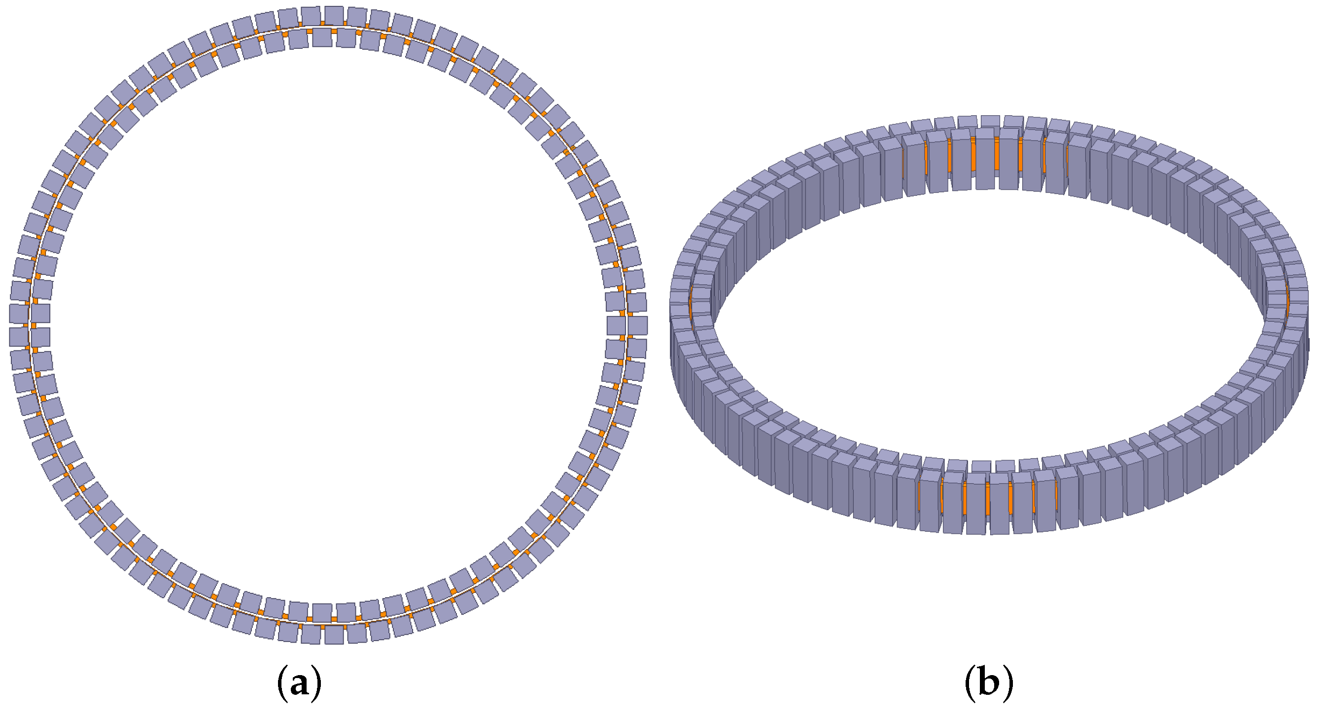
The attention was moved to more practical aspects related to the realization of the ferrite core after the two optimization procedures. Indeed, due to the high fragility of the ferrite, it is not simple to shape the core as desired. The winding slot should be dug on a toroid with a high risk of cracking the material. In addition, vibrations during operation may damage the bulk ferrite cores. Therefore, the possibility to realize them by placing small pieces of ferrites was investigated, as proposed in [15]. In particular, C-shaped ferrites were identified as the most interesting products available on the market. In this way, a further weight reduction was achieved due to the lack of material between adjacent ferrites. It must be noted that this operation is a trade off between the decrease in the coupling between primary and secondary (and therefore a drop in the transferred power) and weight reduction. Therefore, a filling factor around 80% was identified for both the volumes of the cores as the most suitable arrangement. Considering the outcome of the genetic algorithm reported previously as the reference design, this solution led to the placement of 75 ferrites on the innermost core and 85 on the outermost. Each piece of core had a width of 6 and showed the same cross section that can be obtained with the data reported in Table 1. The geometry of the winding was not affected by this operation. Figure 9 shows top and perspective views of the new cores. Despite the removal of ferromagnetic material, the coupling between the two sides of the transformer was still high, and this arrangement allowed us to transfer even more power on the secondary than in the solid core solution, with a weight reduction of 17.6%. The explanation of this result is that the power transfer strongly depends on the particular arrangement of the values , and M, keeping the resistive parameters constant. Indeed:
where due to the ohmic losses on and only. In this operation, the power transfer was not brought to its global maximum point, but it was ensured that the goal of about was still satisfied. The main data that refer to this new configuration are reported in Table 1. It can be noted that, this time, the inductance parameters were intended as average values. Indeed, they depended on the particular alignment between primary and secondary ferrite cores.
5. Validation over a Reduced-Scale Prototype
Finally, the design procedure of rotary transformers proposed in this paper was validated using a small-size prototype due to the cost of realization of a full-scale prototype and the availability of materials. In particular, this test aimed to verify and investigate the possibility of transferring power contactless from primary to secondary with split C-ferrites forming the two cores. The prototype had inner and outer diameters equal to and , respectively, with a 1 air gap between the cores on the two sides. Therefore, forty-six manganese–zinc (MnZn by TDK, model B67350) C-ferrites were used: twenty of them were arranged to form the inner core, whereas the outer core was made with the remaining twenty-six. The size of each C-ferrite is reported in Figure 10.
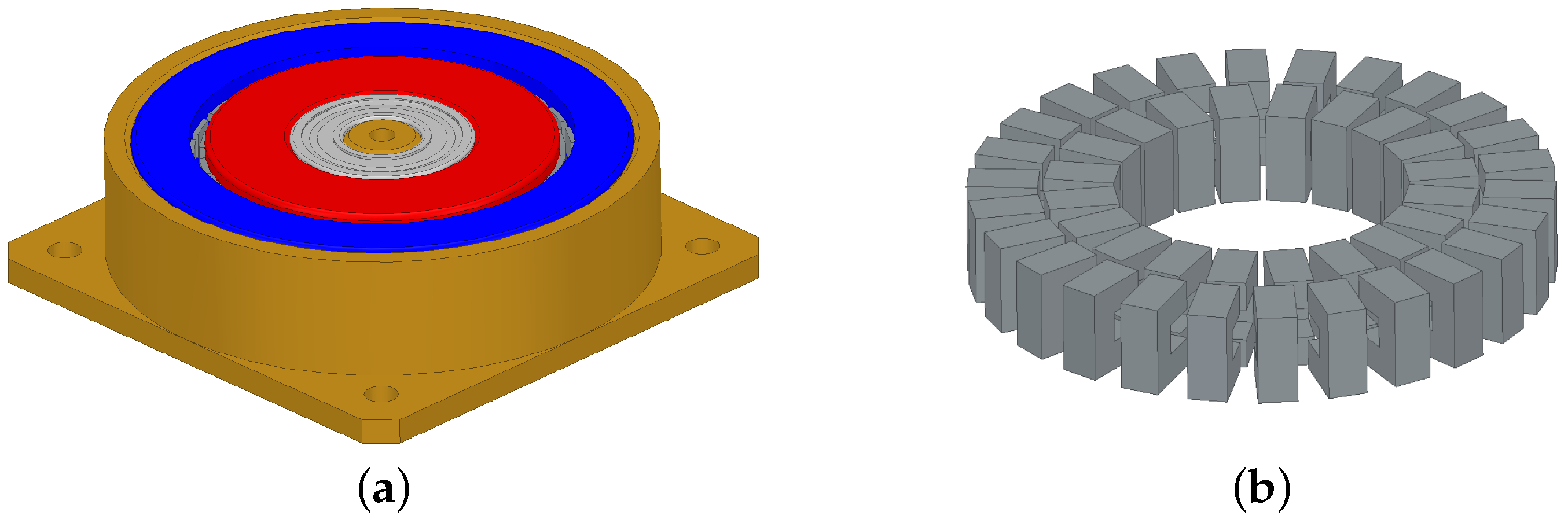
The windings had the same number of turns as the full-scale device, i.e., and , and they were realized with a enamelled copper wire. Three parallel wires were exploited in each coil to limit the values of and . It is important to underline that a support both for keeping the ferrites and the wires in the correct position was needed. Thus, a small structure was created using nylon-fiber with a 3D printer. Figure 11a,b show some details regarding the realization of the cores and the geometry of the supports, as well. In addition to the practical realization of the prototype, a 3D model was created in ANSYS Maxwell (see Figure 12). This model was adopted to perform some predictions on the values of the inductances , and M, in addition to the transferred power , as reported in Table 2. Furthermore, the electrical parameters were identified using the LCR meter LCR-819 by GW-Instek.
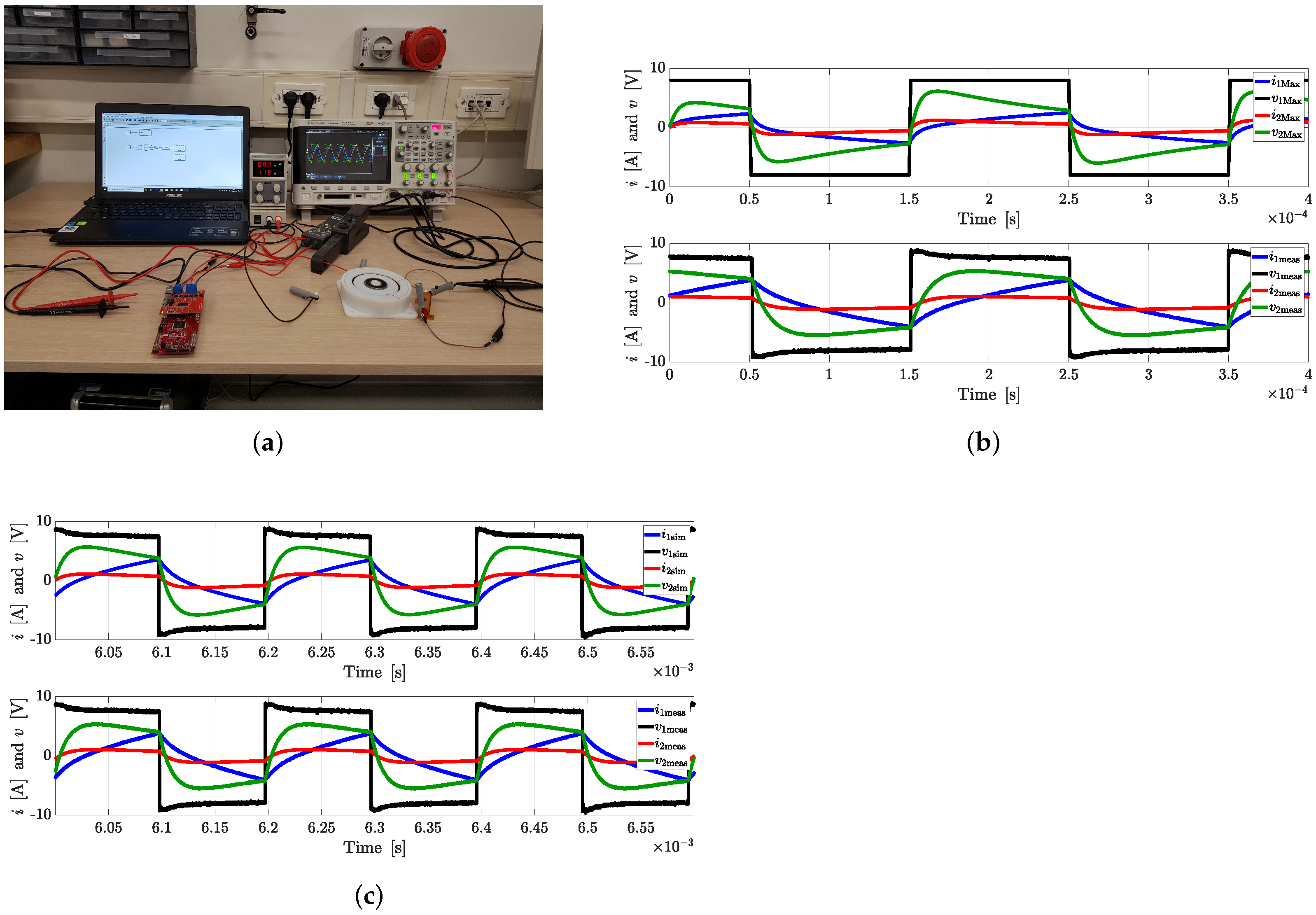
It must be underlined that this device was designed to work with reduced supply voltage and switching frequency as well as load resistance with respect to the full-scale transformer. A first set of tests was performed in these conditions. A square-wave generator was used in ANSYS Maxwell to emulate the behaviour of the H-bridge driven in square-wave modulation adopted in practice to test the power transfer of this device. On the other hand, the evaluation board TI C2000™ LaunchPad™ Piccolo F28069M, together with the converter board TI BOOSTXL-DRV8301 BoosterPack, was adopted in practice for running the power transfer test. Figure 13a shows the adopted setup. Results of both simulation and measurement show that both the inductance and power values were close, despite the fact that the materials could not be exactly characterized in the FEM software, the volume of the coils did not match the actual and the real supply voltage was far from being an ideal square wave. This mismatch in the harmonic content of the input voltages explains and partly justifies the big difference between the resulting shape of the voltage and current waveforms. Figure 13a,b show the real test setup adopted for running these tests and a comparison between the measured waveforms, , , and , and the simulated waveforms.
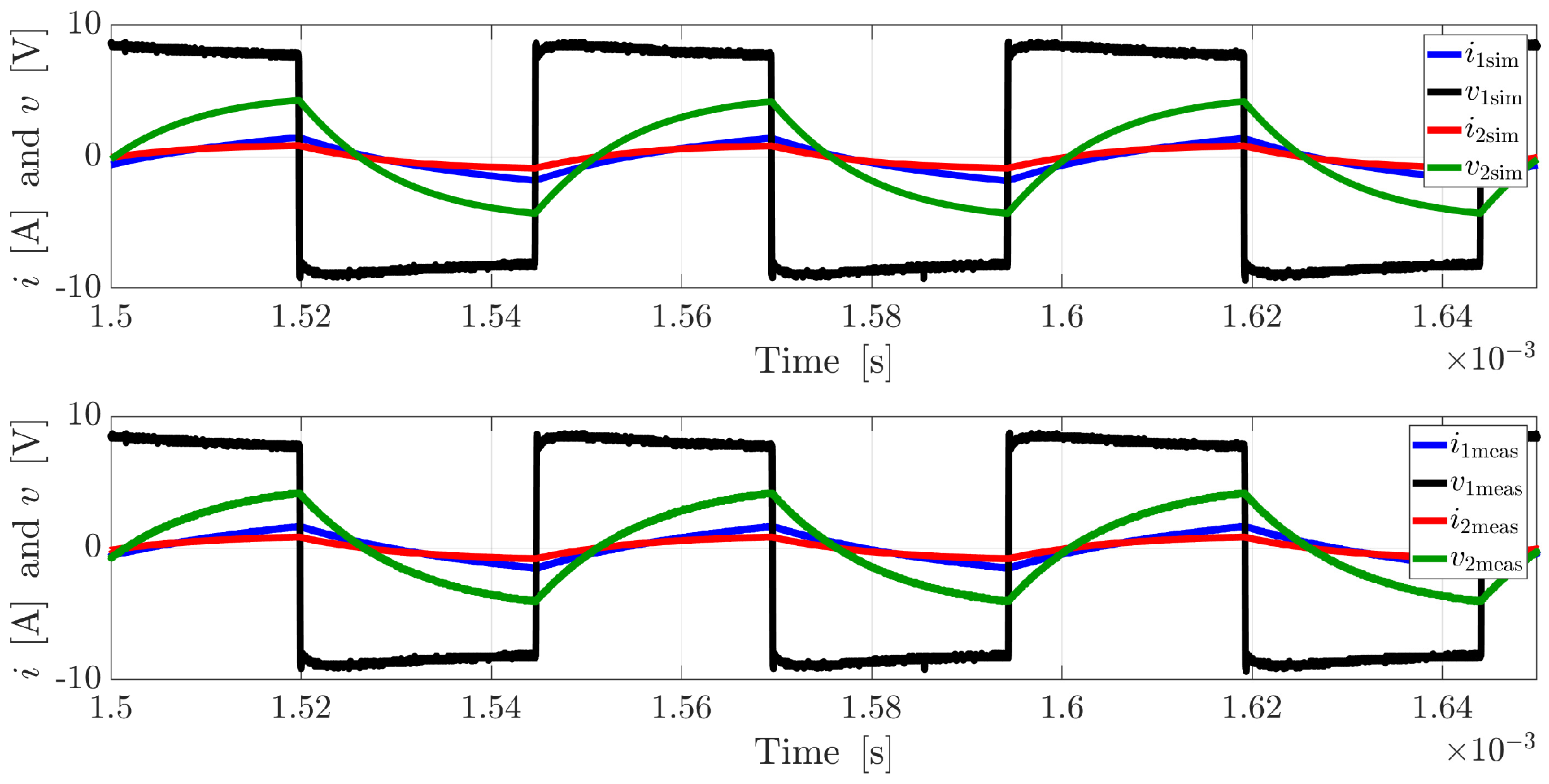
In particular, this picture shows the mismatch in the harmonic content due to the different adopted voltage generators. Hence, to provide a better comparison between the virtual test and the measurements, the parameters identified in ANSYS Maxwell were used to run a simulation in Simulink®. Namely, , and M were inserted in a mutual inductor model and the equivalent circuit reported in Figure 3 was built. In this case, the waveform adopted in the real test was acquired and used to supply the Simulink® scheme through a controlled voltage generator. The results of this virtual test and their comparison with the measurements are reported in Figure 13c, which shows a much better agreement between simulation and test results than before in terms of harmonic content. As a matter of fact, the simulation in Simulink® allowed us to predict a power transfer equal to , which means a difference with respect to the measured value equal to 1.67%. Finally, the Simulink® model could be used to study different working points of the device. As an example, an additional test was carried out at 20 (keeping and ) and compared with simulation, as shown in Figure 14. In order to provide a quantitative mismatch between measured and simulated quantities, Table 3 reports the comparison between the RMS values of , and . The input voltage is not reported there because it is imposed to be the same waveform both in real and simulated tests.
6. Conclusions
Among all the possible applications of rotary transformers, their installations on relatively large shafts are of great interest, since they allow us to use those devices in aerospace applications, such as helicopters, trains, cars and ships, as well as in many industry applications. This paper proposes an example of a preliminary design for a transformer that should transfer around 4 from primary to secondary, considering a resistive load of 20 . To this aim, three cascaded optimization procedures were carried out. The grid-search and the genetic optimizations were aimed at finding the best geometrical and electrical arrangements for the rotary transformer by applying some constraints on its size. Because of its installation on shafts, one goal of these procedures was the minimization of the weight of the device, which translates to a minimization of the additional inertia applied on the rotating part of the system. In these optimizations, special attention was also paid on setting sufficiently conservative limits on the current density on the coils and saturation of the two magnetic cores. The third step was meant to reduce the weight of the magnetic core, in addition to limiting the risk of cracking the bulk ferrite. These two goals were achieved by slicing the cores. This design choice of splitting the main structure using small C-ferrite cores was validated using a reduced-scale prototype. Moreover, this new design was realized following the same procedure reported in this paper. Therefore, this validation is intended both to check the actual possibility to transfer power from primary to secondary using sliced cores and to prove that the developed design steps provide the desired results. Additionally, the verification highlights that the models developed during this study provide accurate predictions despite all the uncertainties encountered in the modelling phase. This can be realized comparing simulation and measurement results. ANSYS Maxwell was used mainly to estimate the inductance matrix of the device; however, it had a great mismatch in the prediction of the harmonic content of each waveform. This deviation was mainly due to the impossibility of imposing the same input voltage adopted in the real system. Conversely, this constraint can be set in Simulink®; in this framework, the identified inductance matrix can be combined with working conditions which can deviate from the nominal conditions, allowing us to predict voltages, currents and transferred power for a wide set of working points, reducing the simulation time (compared to 3D FEM co-simulation runs). Future work can focus on the realization of a prototype able to transfer 3– from primary to secondary tailored for a specific application and on the validation of the prediction on the full-size device.
Author Contributions
Conceptualization, M.B., F.C.D. and M.M.; Formal analysis, N.T. and M.M.; Funding acquisition, M.B., F.C.D. and M.M.; Investigation, N.T.; Methodology, M.S.C.; Project administration, M.B.; Supervision, M.B., M.S.C., F.C.D. and M.M.; Validation, N.T.; Writing—original draft, N.T.; Writing—review and editing, M.B., M.S.C., F.C.D. and M.M. All authors have read and agreed to the published version of the manuscript.
Funding
This research received no external funding.
Institutional Review Board Statement
Not applicable.
Informed Consent Statement
Not applicable.
Conflicts of Interest
The authors declare no conflict of interest.
References
- She, X.; Huang, A.Q.; Burgos, R. Review of Solid State Transformer Technologies and Their Application in Power Distribution. IEEE J. Emerg. Sel. Top. Power Electron. 2013, 1, 186–198. [Google Scholar] [CrossRef]
- Landsman, E.E. Rotary transformer design. In Proceedings of the IEEE Power Electronics Specialists Conference, Greenbelt, MD, USA, 20–21 April 1970. [Google Scholar]
- Papastergiou, K.D.; Macpherson, D.E. Contact-less transfer of energy by means of a rotating transformer. In Proceedings of the 2005 IEEE International Symposium on Industrial Electronics IV, Dubrovnik, Croatia, 20–23 June 2005; pp. 1735–1740. [Google Scholar]
- Roberts, G.; Owens, A.R.; Lane, P.M.; Humphries, M.E.; Child, R.K.; Bauder, F.; Izquierdo, J.M.G. A contactless transfer device for power and data. In Proceedings of the IEEE Aerospace Applications Conference, Aspen, CO, USA, 10 February 1996. [Google Scholar]
- Zhong, H.; Wu, C.; Wang, Y. Design and analysis of rotary transformer for brushless doubly fed induction generators. In Proceedings of the 13th IEEE Conference on Industrial Electronics and Applications (ICIEA), Wuhan, China, 31 May–2 June 2018; pp. 1416–1419. [Google Scholar]
- Zietsman, N.L.; Gule, N. Design and evaluation of a 1.2 kVA single phase rotary transformer. In Proceedings of the 22nd International Conference on Electrical Machines (ICEM), Lausanne, Switzerland, 4–7 September 2016; pp. 1466–1472. [Google Scholar]
- Ruviaro, M.; Rüncos, F.; Sadowski, N. Wound rotor doubly fed induction machine with radial rotary transformer. J. Microwaves Optoelectron. Electromagn. Appl. 2013, 12, 411–426. [Google Scholar] [CrossRef]
- Krupp, H.; Mertens, A. Rotary transformer design for brushless electrically excited synchronous machines. In Proceedings of the 2015 IEEE Vehicle Power and Propulsion Conference (VPPC 2015), Montreal, QC, Canada, 19–22 October 2015. [Google Scholar]
- Dolara, A.; Leva, S.; Longo, M.; Mauri, M.; Castelli-Dezza, F. Coil design and magnetic shielding of a resonant wireless power transfer system for electric vehicle battery charging. In Proceedings of the 2017 6th International Conference on Renewable Energy Research and Applications, ICRERA 2017, San Diego, CA, USA, 5–8 November 2017; pp. 200–205. [Google Scholar]
- Maglio, M.M.; Carmeli, M.S.; Mauri, M.; Castelli-Dezza, F. Design and analysis of a high frequency wireless power feeding system for train axle telemetry. In Proceedings of the 2014 International Symposium on Power Electronics, Electrical Drives, Automation and Motion, SPEEDAM 2014, Ischia, Italy, 18–20 June 2014; pp. 527–532. [Google Scholar]
- Brunetti, M.; Chatterton, S.; Carmeli, M.S.; Mauri, M.; Castelli-Dezza, F. Wireless power transfer with temperature monitoring interface for helicopter rotor blade ice protection. In Proceedings of the AIAA Propulsion and Energy 2020 Forum, Virtual Event, 24–28 August 2020; pp. 1–11. [Google Scholar]
- Bellussi, E.; Brunetti, M.; Dezza, F.C.; Chatterton, S.; Facchini, G.; Mauri, M.; Ostuni, N.; Toscani, N. Rotor for a Hover-Capable Aircraft. European Patent Application EP3845458A1, 7 July 2021. [Google Scholar]
- Smeets, J.P.C.; Encica, L.; Lomonova, E.A. Comparison of Winding Topologies in a Pot Core Rotating Transformer. In Proceedings of the 12th International Conference on Optimization of Electrical and Electronic Equipment, Basov, Romania, 20–22 May 2010; pp. 103–110. [Google Scholar]
- Kalyanmoy, D. Multi-Objective Optimization Using Evolutionary Algorithms; John Wiley & Sons: Hoboken, NJ, USA, 2001. [Google Scholar]
- Abdolkhani, A.; Hu, A.; Nair, N. Modelling and Parameters Identification of Through-Hole Type Wind Turbine Contactless Sliprings. Engineering 2012, 4, 272–283. [Google Scholar] [CrossRef] [Green Version]
- Umans, S.D. Fitzgerald & Kingsley’s Electric Machinery, 7th ed.; McGraw-Hill International Edition: New York, NY, USA, 2014. [Google Scholar]
- Hurley, W.G.; Wölfle, W.H.; Breslin, J.G. Optimized transformer design: Inclusive of high-frequency effects. IEEE Trans. Power Electron. 1998, 13, 651–659. [Google Scholar] [CrossRef]
- Orosz, T. Evolution and Modern Approaches of the Power Transformer Cost Optimization Methods. Period. Polytech. Electr. Eng. Comput. Sci. 2019, 63, 37–50. [Google Scholar] [CrossRef] [Green Version]
- Legranger, J.; Friedrich, G.; Vivier, S.; Mipo, J.C. Comparison of Two Optimal Rotary Transformer Designs for Highly Constrained Applications. In Proceedings of the IEEE International Electric Machines & Drives Conference, Antalya, Turkey, 9–12 May 2007. [Google Scholar]
- William, T.; McLyman, C. Transformer and Inductor Design Handbook, 4th ed.; CRC Press: Boca Raton, FL, USA, 2011. [Google Scholar]
- Aditya, K.; Williamson, S.S. Comparative study of Series-Series and Series-Parallel compensation topologies for electric vehicle charging. In Proceedings of the 2014 IEEE International Symposium on Industrial Electronics, Istanbul, Turkey, 1–4 June 2014; pp. 426–430. [Google Scholar]
- Dolara, A.; Leva, S.; Longo, M.; Castelli-Dezza, F.; Mauri, M. Analysis of control strategies for compensated inductive power transfer system for electric vehicles charging. In Proceedings of the 2017 17th IEEE International Conference on Environment and Electrical Engineering and 2017 1st IEEE Industrial and Commercial Power Systems Europe (EEEIC), Milan, Italy, 6–9 June 2017; pp. 1–6. [Google Scholar]
- Truong, B.D.; Roundy, C.; Andersen, E.; Roundy, S. Analysis of resonance and anti-resonance frequencies in a Wireless Power Transfer System: Analytical model and experiments. IEEE Trans. Circuits Syst. II Express Briefs 2019, 66, 1222–1226. [Google Scholar] [CrossRef]
- Sohn, Y.H.; Choi, B.H.; Lee, E.S.; Lim, G.C.; Cho, G.; Rim, C.T. General Unified Analyses of Two-Capacitor Inductive Power Transfer Systems: Equivalence of Current-Source SS and SP Compensations. IEEE Trans. Power Electron. 2015, 30, 6030–6045. [Google Scholar] [CrossRef]
- Imaoka, J.; Nam, M.; Shoyama, M.; Fujita, H. Design of Series-Parallel combined resonant circuit with rotary transformer used for ultrasonic spindle drive. In Proceedings of the IEEE 3rd International Future Energy Electronics Conference and ECCE Asia (IFEEC—ECCE Asia), Kaohsiung, Taiwan, 3–7 June 2017; pp. 2244–2249. [Google Scholar]
- Cho, S.Y.; Lee, I.O.; Moon, S.C.; Moon, G.W.; Kim, B.C.; Kim, K.Y. Series-Series compensated wireless power transfer at two different resonant frequencies. In Proceedings of the 2013 IEEE ECCE Asia Downunder—5th IEEE Annual International Energy Conversion Congress and Exhibition, Melbourne, VIC, Australia, 3–6 June 2013; pp. 1052–1058. [Google Scholar]
- Godbehere, J.; Hopkins, A.; Yuan, X. Design and Thermal Analysis of a Rotating Transformer. In Proceedings of the IEEE International Electric Machines & Drives Conference (IEMDC), San Diego, CA, USA, 12–15 May 2019. [Google Scholar]
- Amoiralis, E.I.; Tsili, M.A.; Kladas, A.G. Transformer Design and Optimization: A Literature Survey. IEEE Trans. Power Deliv. 2019, 24, 1999–2024. [Google Scholar] [CrossRef]
- Orosz, T.; Pánek, D.; Karban, P. FEM Based Preliminary Design Optimization in Case of Large Power Transformers. Appl. Sci. 2020, 10, 1361. [Google Scholar] [CrossRef] [Green Version]
Figure 1.
Coaxial topology for rotary transformers.

Figure 2.
Equivalent circuit of the rotary transformer with mutual inductor.
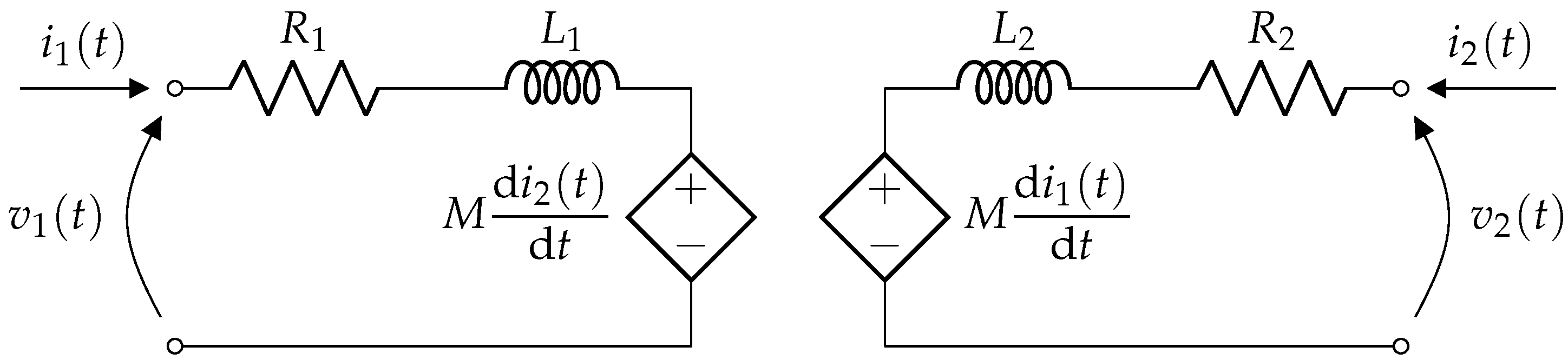
Figure 3.
Equivalent circuit of the rotary transformer with mutual inductor: phasor domain.

Figure 4.
Rotary transformer with series compensation of : (a) single-capacitor compensation and (b) dual-capacitor compensation.
Figure 4.
Rotary transformer with series compensation of : (a) single-capacitor compensation and (b) dual-capacitor compensation.
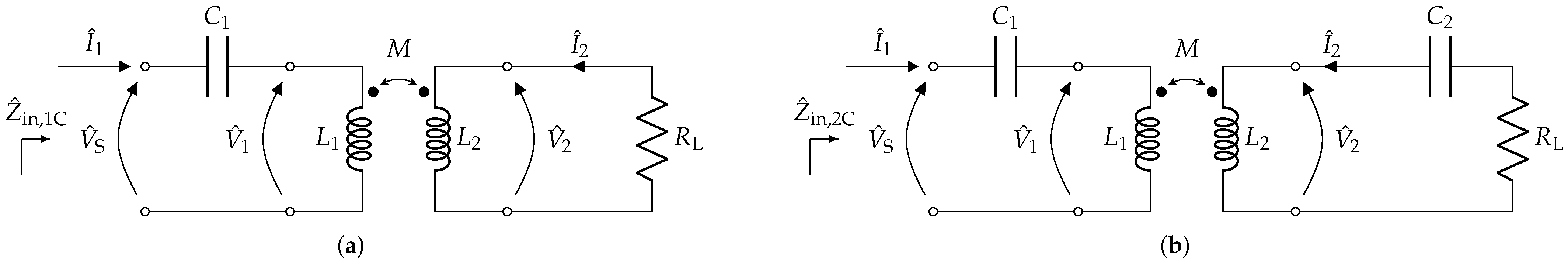
Figure 5.
Equivalent circuit of the rotary transformer supplied by a full-bridge converter. For the sake of simplicity, no compensation is reported in this picture.
Figure 5.
Equivalent circuit of the rotary transformer supplied by a full-bridge converter. For the sake of simplicity, no compensation is reported in this picture.

Figure 6.
Density plot of the absolute value of the induction field superimposed to the field lines of the real part of the magnetic vector potential for a realistic geometrical configuration of the rotary transformer.
Figure 6.
Density plot of the absolute value of the induction field superimposed to the field lines of the real part of the magnetic vector potential for a realistic geometrical configuration of the rotary transformer.
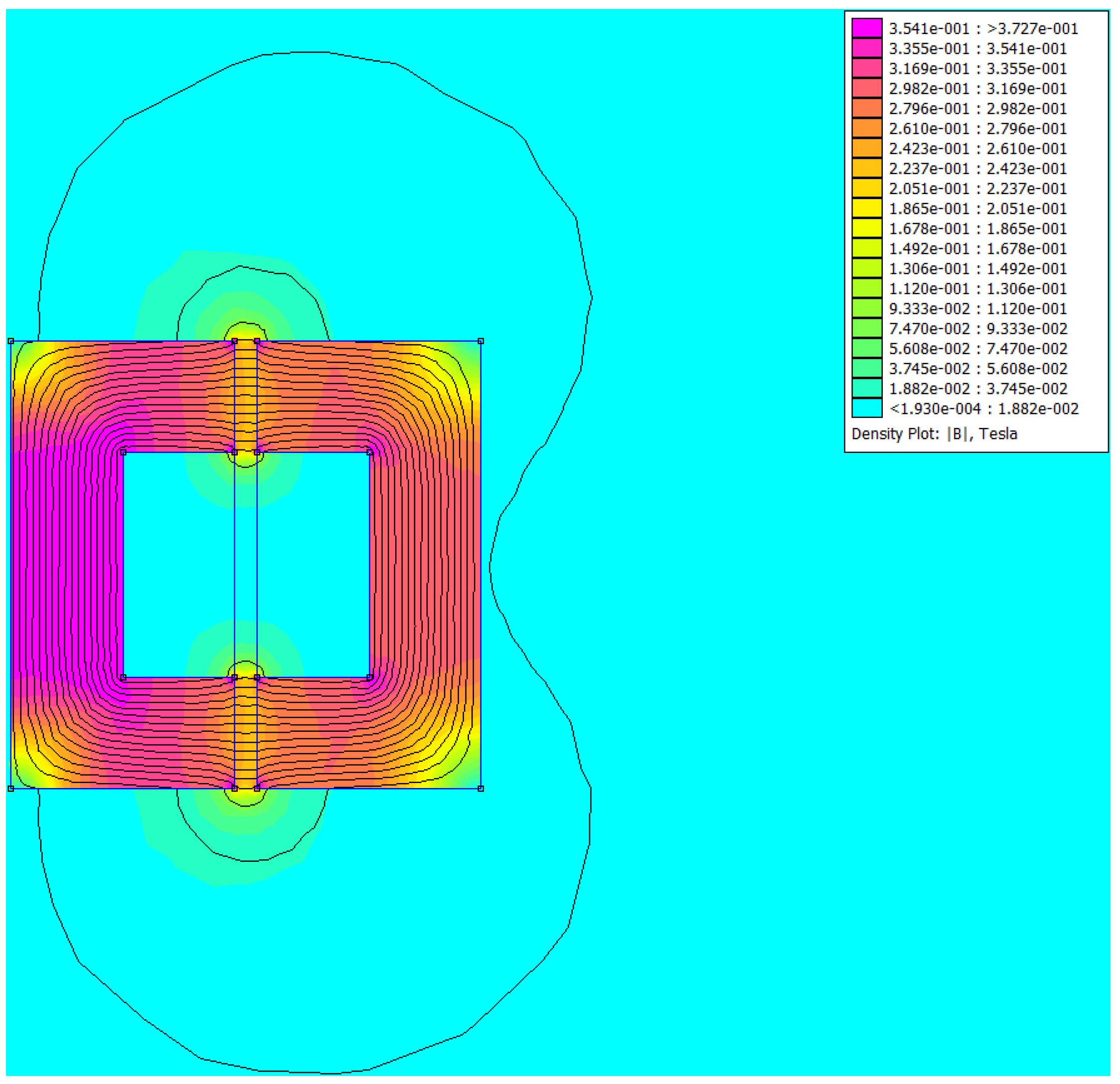
Figure 7.
Electromagnetic model of the rotary transformer in ANSYS Maxwell: (a) shows top view and (b) shows front view of a generic slice of the transformer, whereas (c) shows the complete 3D model.
Figure 7.
Electromagnetic model of the rotary transformer in ANSYS Maxwell: (a) shows top view and (b) shows front view of a generic slice of the transformer, whereas (c) shows the complete 3D model.
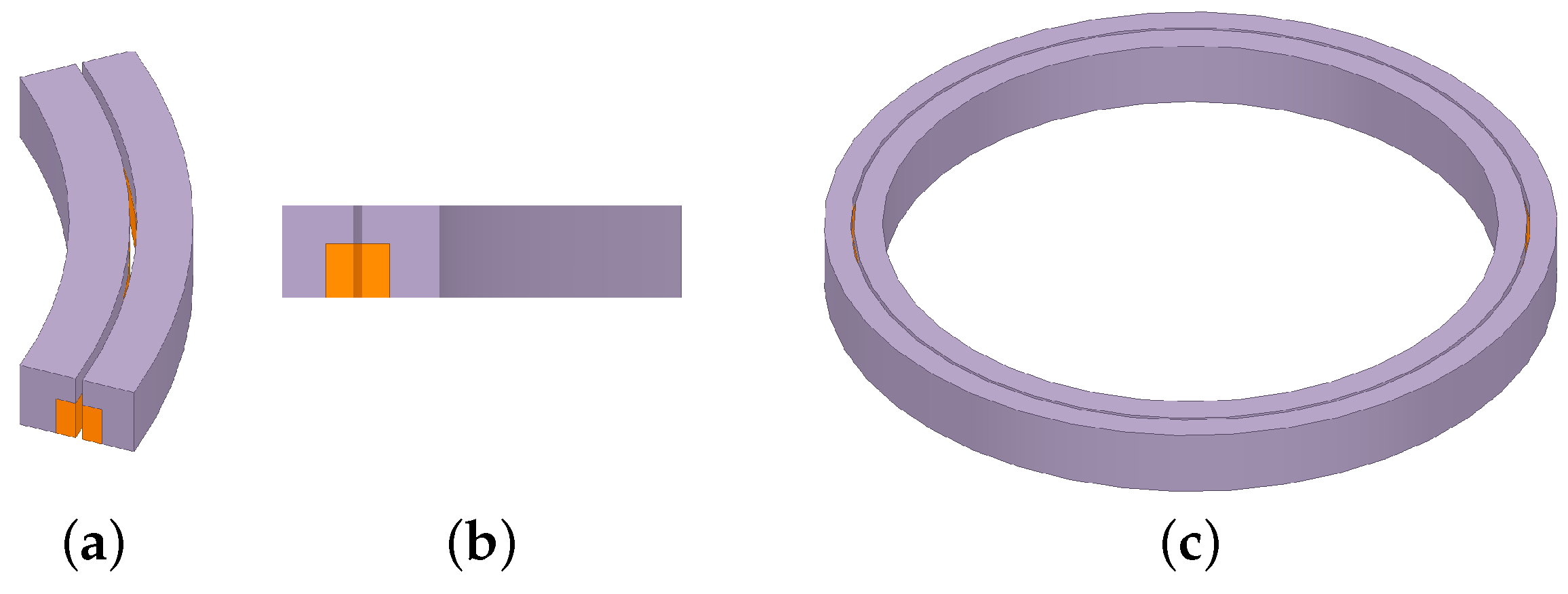
Figure 8.
Geometrical parameters of the magnetic core.
Figure 9.
Electromagnetic model of the rotary transformer with C-shaped ferrites forming the cores: (a) top and (b) perspective views of the complete 3D model.
Figure 9.
Electromagnetic model of the rotary transformer with C-shaped ferrites forming the cores: (a) top and (b) perspective views of the complete 3D model.

Figure 10.
Geometrical dimensions of each C-ferrite adopted in the reduced-size prototype. Quotes are reported in .
Figure 10.
Geometrical dimensions of each C-ferrite adopted in the reduced-size prototype. Quotes are reported in .

Figure 11.
Reduced-size prototype. Both (a,b) allow us to appreciate some details in the realization of the core and the windings.
Figure 11.
Reduced-size prototype. Both (a,b) allow us to appreciate some details in the realization of the core and the windings.
Figure 12.
FEMM model of the small-size prototype realized in ANSYS Maxwell: rotary transformer with supports (a) and cores realized with C-shaped ferrites (b).
Figure 12.
FEMM model of the small-size prototype realized in ANSYS Maxwell: rotary transformer with supports (a) and cores realized with C-shaped ferrites (b).

Figure 13.
Experimental setup (a), comparison between the measured and simulated voltages and currents in ANSYS Maxwell (b) and comparison between measured and simulated voltages and currents in Simulink® (c). In (b,c) the system is working at 5 . RMS values for , and are reported in Table 3.
Figure 13.
Experimental setup (a), comparison between the measured and simulated voltages and currents in ANSYS Maxwell (b) and comparison between measured and simulated voltages and currents in Simulink® (c). In (b,c) the system is working at 5 . RMS values for , and are reported in Table 3.

Figure 14.
Comparison between the measured and simulated voltages and currents in Simulink®. In this picture, the device is supplied with a 20 waveform. RMS values for , and are reported in Table 3.
Figure 14.
Comparison between the measured and simulated voltages and currents in Simulink®. In this picture, the device is supplied with a 20 waveform. RMS values for , and are reported in Table 3.


Table 1.
Comparison between the results obtained in the three optimization procedures.
| Parameter | Grid-Search | Genetic Algorithm | C-Ferrites |
|---|---|---|---|
| 7 | 11 | 11 | |
| 7 | 13 | 13 | |
| Weight |
Table 2.
Measured vs. estimated transformer parameters. Supply frequency .
| Parameter | Measured | ANSYS Maxwell® | |
|---|---|---|---|
| 114 | 104 | 8.47% | |
| 165 | 142 | 13.9% | |
| M | 100 | 105 | 4.96% |
| 1.72% |
Publisher’s Note: MDPI stays neutral with regard to jurisdictional claims in published maps and institutional affiliations. |
© 2022 by the authors. Licensee MDPI, Basel, Switzerland. This article is an open access article distributed under the terms and conditions of the Creative Commons Attribution (CC BY) license (https://creativecommons.org/licenses/by/4.0/).
Share and Cite
MDPI and ACS Style
Toscani, N.; Brunetti, M.; Carmeli, M.S.; Castelli Dezza, F.; Mauri, M. Design of a Rotary Transformer for Installations on Large Shafts. Appl. Sci. 2022, 12, 2932. https://doi.org/10.3390/app12062932
AMA Style
Toscani N, Brunetti M, Carmeli MS, Castelli Dezza F, Mauri M. Design of a Rotary Transformer for Installations on Large Shafts. Applied Sciences. 2022; 12(6):2932. https://doi.org/10.3390/app12062932
Chicago/Turabian StyleToscani, Nicola, Massimo Brunetti, Maria Stefania Carmeli, Francesco Castelli Dezza, and Marco Mauri. 2022. "Design of a Rotary Transformer for Installations on Large Shafts" Applied Sciences 12, no. 6: 2932. https://doi.org/10.3390/app12062932
Note that from the first issue of 2016, this journal uses article numbers instead of page numbers. See further details here.