Article

Modeling and Analysis of a High-Speed Adjustable Grasping Robot Controlled by a Pneumatic Actuator

1
Faculty of Science and Technology, Meijo University, Nagoya 468-8502, Japan
2
Department of Mechatronics Engineering, Graduate School of Science and Technology, Meijo University, Nagoya 468-8502, Japan
*
Author to whom correspondence should be addressed.
Robotics 2022, 11(1), 27; https://doi.org/10.3390/robotics11010027
Submission received: 25 December 2021 / Revised: 24 January 2022 / Accepted: 2 February 2022 / Published: 12 February 2022
(This article belongs to the Section Sensors and Control in Robotics)

Abstract

:
This paper discusses the modeling and analysis of a high-speed adjustable grasping robot controlled by a pneumatic actuator. The robot is composed of two grippers, two wires for connecting a pneumatic cylinder and an arm with gripper joints with a spring as well as two stoppers for controlling the gripper stopping point with a brake. By supplying pressurized air into the pneumatic cylinder, the two grippers move forward together with the arm and capture the object by adjusting the air pressure in the cylinder. After capturing the target object, the system can release the object by changing the pressure air in the air cylinder using another port. By considering the state equation of the air, we obtain a dynamic model of the robot, including the actuator. Through numerical simulation, we show that the simulation results can explain the experimental results from the developed robot system. Through our experiments, we confirm that the developed high-speed grasping robot can grasp continuously moving objects with a gap of ±15 mm at 300 mm/s.

1. Introduction

In order to grasp high-speed moving objects in a production line, a grasping system, which includes sensing, actuation and control software, should have a high response. From the viewpoint of actuation, high-speed robotic systems have been proposed and developed thus far [1,2,3,4,5,6,7,8,9,10,11,12,13,14,15,16,17,18,19,20]. For example, Namiki et al. developed a lightweight and high-speed multi-fingered robot gripper that can open and close with 180° in 0.1 s [1]. The high-speed robot arm developed by Namiki et al. has a low deceleration ratio of 1:50 for each axis in order to maximize the instantaneous torque rather than the sustained holding force.
This makes it possible to move the robot arm several times faster than conventional robot arms. Using the aforementioned high-speed arm and multi-fingered robot hand, catching [2], juggling [3], Kendama [4] and dynamic tying [5] have been proposed. In addition, combined robot hand systems with both high-speed and large grasping forces have been also proposed. At first, the gearless motor is used until the gripper touches to the target object. After that, a geared motor with large torque is used for the grasping phase [6,7].
Research has been conducted to combine high-speed grippers with sensors and force-regulation mechanisms to grasp fragile objects at high-speed [8,9]. In the field of soft robotics, several grippers have been developed that focus on high-speed grasping [10,11]. These soft grippers show good characteristics, including being light weight and having low energy consumption and high-speed grasping. Toward achieving high-speed abilities, Kaneko et al. proposed a 100 gravity acceleration capturing robot [12] that can grasp a free-falling object. The robot uses a compression spring as its energy source in order to achieve the high acceleration of 100 gravity acceleration.
By releasing the spring energy, the robot moves in a linear motion at high speeds, and the kinetic energy generated by the linear motion is used for the rotational motion to close the gripper. However, the robot was not designed to release the grasped object appropriately, because the robot was optimized to realize high-speed grasping motion.
There have been many other works discussing high-speed robotic hand motion and high-speed grasping systems [13,14,15,16,17,18,19].
In this study, we developed a high-speed grasping robot with grasping and releasing motions by considering a novel mechanism. In our previous paper [20], we confirmed that the developed high-speed grasping robot could grasp an object in about 0.04 s and release an object in about 0.11 s. In the experiment of grasping a moving object, the distance of the arm movement was fixed at 35 mm, and the object was moved with the speeds from 50 mm/s to 300 mm/s. Within these speeds, an object was captured with a success rate of 30 / 30 trials.
However, the previous model was only a preliminary system. Thus, the detailed mechanism modeling and its evaluation were not considered. In this paper, we describe the model for the design of a high-speed grasping robot and evaluate this model through simulations and experiments. Additionally, we encountered issues (as shown in Figure 1) when grasping a moving object.
As shown in Figure 1a, if the distance between the robot and target objects is adjusted as pre-defined in advance, the robot can grasp the object successfully. However, if the relationship between the robot and the object is different from the pre-defined setup, the robot may result in failing to grasp the object as shown in Figure 1b,c.
The horizontal arrows in Figure 1 show the arm motion produced by the pneumatic actuator, and the details of the actuation mechanism are given in Figure 2. To cope with these issues, we include a braking mechanism, which makes it possible to quickly adjust the grasping position according to the position of the object with sensor feedback control.
The goals of this paper are (1) to show the mechanical configuration of the newly developed high-speed grasping robot, (2) to construct a dynamic simulation model for the newly developed high-speed grasping robot and to compare between the results obtained by simulation and those obtained by experiments and (3) to show capturing demonstrations of the object moving on the conveyor.
The remainder of this paper is organized as follows: Section 2 describes the design of the proposed high-speed grasping robot, Section 3 describes mechanical model of the high-speed grasping robot, and Section 4 describes the details of the experimental setup as well as the comparison between the simulation and experiment precisely, together with the demonstration of capturing objects on the conveyor. Experimental results for various properties of the objects are also shown so that we can see how the success rate changes depending upon the properties of the objects.
Section 5 concludes and discusses future work.

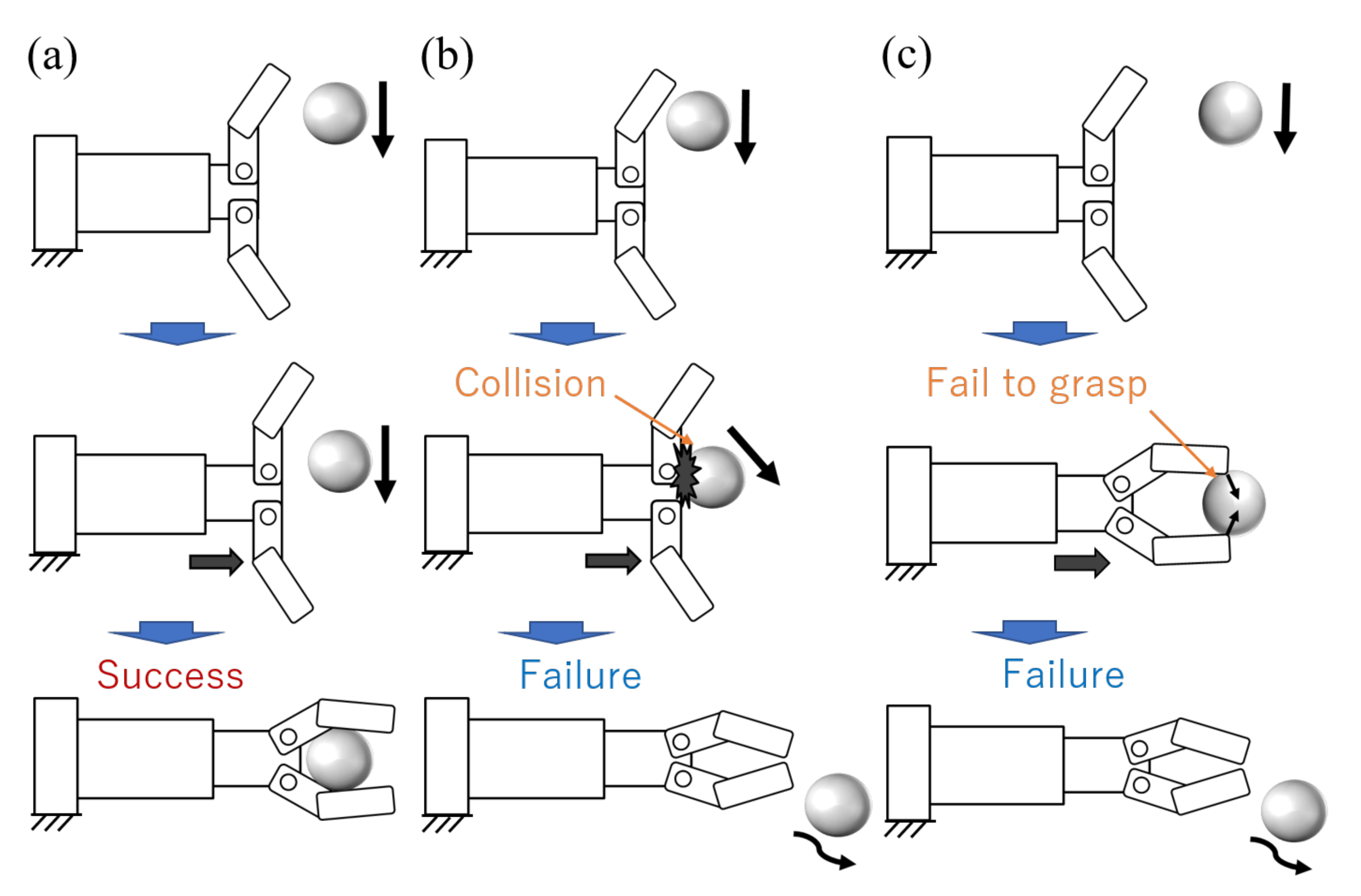
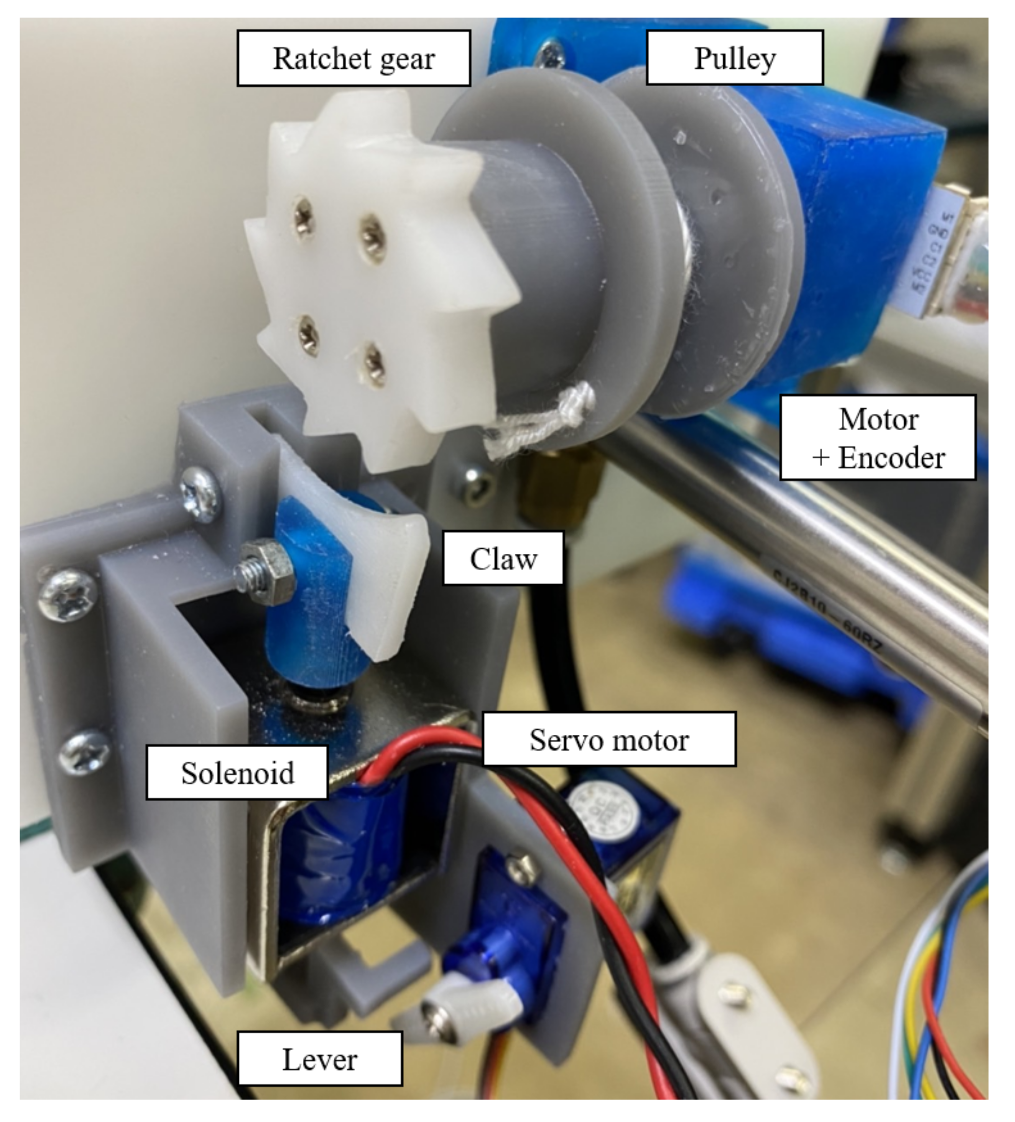
2. Design of the Proposed Robot

Figure 2 explains the basic working principles of the robot with the capability to adjust the grasping position. The robot is composed of a pneumatic actuator, two grippers, a red wire connecting the red stopper and the gripper joints with a spring, as well as a blue wire connecting the blue stopper and a pulley that is connected to a motor with an encoder and a brake for locking the end of the blue wire.
The red stopper includes a hole at the center so that the blue wire may freely move through the red stopper. In the same way, the blue stopper includes a hole at the center so that the red wire may freely move through the blue stopper. This simple mechanism contributes to transferring the arm-translational energy produced by the pneumatic actuator into the gripper rotational energy without a loss of energy [12]. The role of the brake is to fix the length of the blue stopper so that the target object may be captured appropriately.
Suppose that the object position is always the same on the belt conveyor. In this case, we can keep the length of the blue wire constant after adjusting the length manually. On the other hand, when the object position changes according to objects, the length of the blue wire has to be changed so that the object may be captured appropriately. To do this action, both a distance sensor and a brake are necessary. The object releasing action can be achieved by simply reversing the piston movement.
Precise robot motions are described in the following. A pneumatic cylinder is used to drive the arm, where the compressed air pushes the pneumatic cylinder rod to drive the arm. When the arm is pushed out, the red stopper is attached to the blue stopper, and eventually the blue wire makes the pulley rotate. The amount of rotation of the pulley is measured by the encoder attached to the shaft of the pulley. The amount of rotation of the pulley corresponds to the movement of the arm.
When the arm reaches the target position, the rotation of the pulley is braked and the blue stopper stops. This action eventually makes the tension of the red wire increase. This tension increase causes the robot to start the grasping motion. The above operation realizes the sensor feedback control for adjustment of the grasping position. To return the robot to the initial position, the solenoid valve switches the compressed air supply port and makes the pneumatic cylinder rod reset.
This causes the arm to retract, loosening the red wire on the gripper side and opening the spring attached to the base of the gripper. The motor rewinds the blue wire and returns the origination of the pulley.

3. Modeling of Mechanism

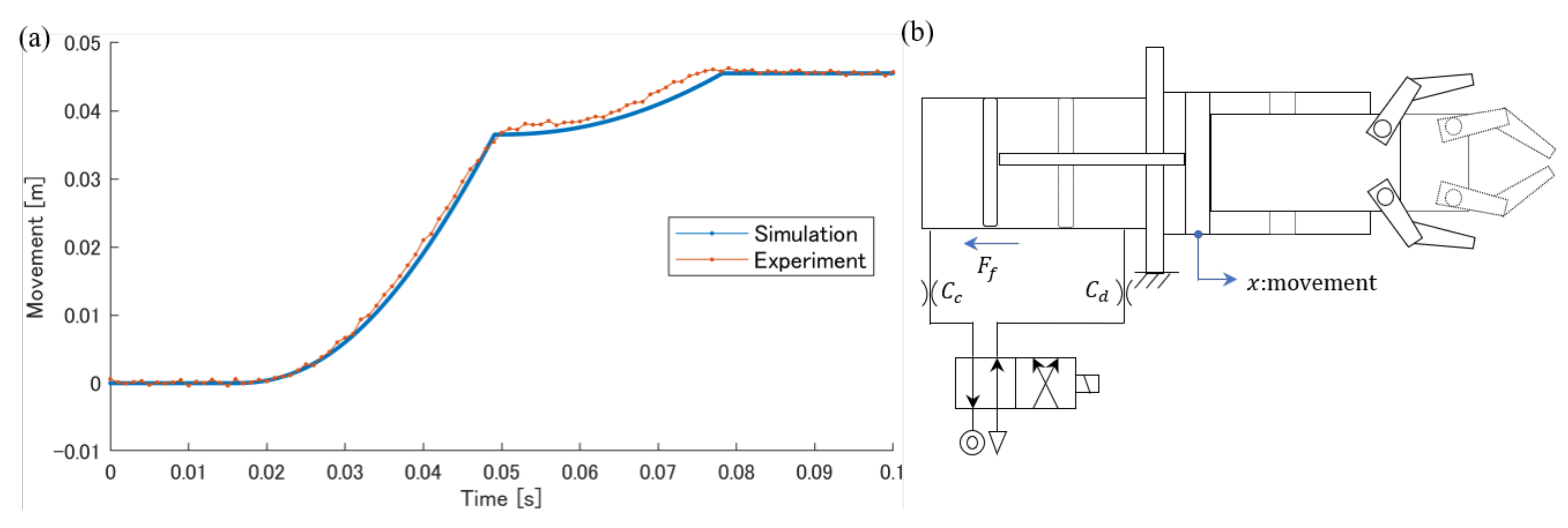
3.1. Modeling of the Driving Part

The modeling of the driving part is shown in Figure 3. The driving part consists of a pneumatic cylinder with the arm mass of m. The response of the robot can be linked with the response of the pneumatic cylinder. From the state equations of air, we obtain the following Equations (1) and (2) [21]:
V c d P c d t = S c P c v + R θ c G c + P c V c θ c d θ c d t
V d d P d d t = S d P d v + R θ d G d + P d V d θ d d θ d d t
where P is the pressure, v is the velocity, S is the area of pressure, θ is the temperature, V is the volume, R is the gas constant of air and G is the mass flow rate. The subscripts c and d refer to the charge side and the discharge side, respectively.
From the conservation of energy and the state equations of air, we obtain the following Equations (3) and (4):
c v P c V c R θ c d θ c d t = c v G c ( θ a θ c ) + R θ a G c S c P c v + h c S h c ( θ a θ c )
c v P d V d R θ d d θ d d t = R θ d G d + S d P d v + h d S h d ( θ a θ d )
where c v is the specific heat at constant volume, h is the heat transfer coefficient, S h is the area of heat transfer and the subscript a denotes the atmosphere.
The mechanical friction is given by Equation (5):
F f = F s v = 0 F c + c l v v 0
where F s is the static friction force, F c is the Coulomb friction force and c l is the linear viscous friction coefficient.
From the equations, we obtain Equation (6):
m d v d t = S c P c S d P d P a ( S c S d ) F f
From the flow equation, we obtain the following Equations (7)–(9):
G c = C c P s ρ 0 θ 0 θ a ϕ ( P s , P c )
G d = C d P d ρ 0 θ 0 θ d ϕ ( P d , P a )
where the function ϕ is defined as
ϕ = 1 P 2 / P 1 b 1 ( P 2 / P 1 b 1 b ) 2 P 2 / P 1 > b
where C is the sonic conductance and b is the critical pressure ratio. ρ 0 refers to the air density.
Using the equations above, we can obtain the dynamic response of the robot (position, velocity and acceleration).

3.2. Modeling of Gripper Part

Figure 4 shows the modeling of the gripper part. The relation between the tension T and finger moment M is given as Equation (10):
M = ( T 2 sin α F k sin β ) L
where F k is the spring reaction force, L is the length between A and B, α is the angle between C A and A B and β is the angle between B A and A D .
The equations of motion for rotational motion are
J δ ¨ + c r δ ˙ = M
where J is the moment of inertia of the gripper, c r is the rotational coefficient associated with the rotational movement of the gripper and δ is the opening and closing angle of the gripper.
The movement speed of the arm v and the rotation speed of the gripper δ ˙ have the following relationship.
v = r δ ˙
where r is the radius of the pulley attached to the base of the gripper. By adding Equations (11) and (12) to Equations (1)–(9), the response of the robot after colliding with the stopper can be expressed.
Finally, the specifications of the gripper parameters are shown in Table 1. In this paper, F k was obtained from a preliminary experiment.

4. Evaluation Experiments

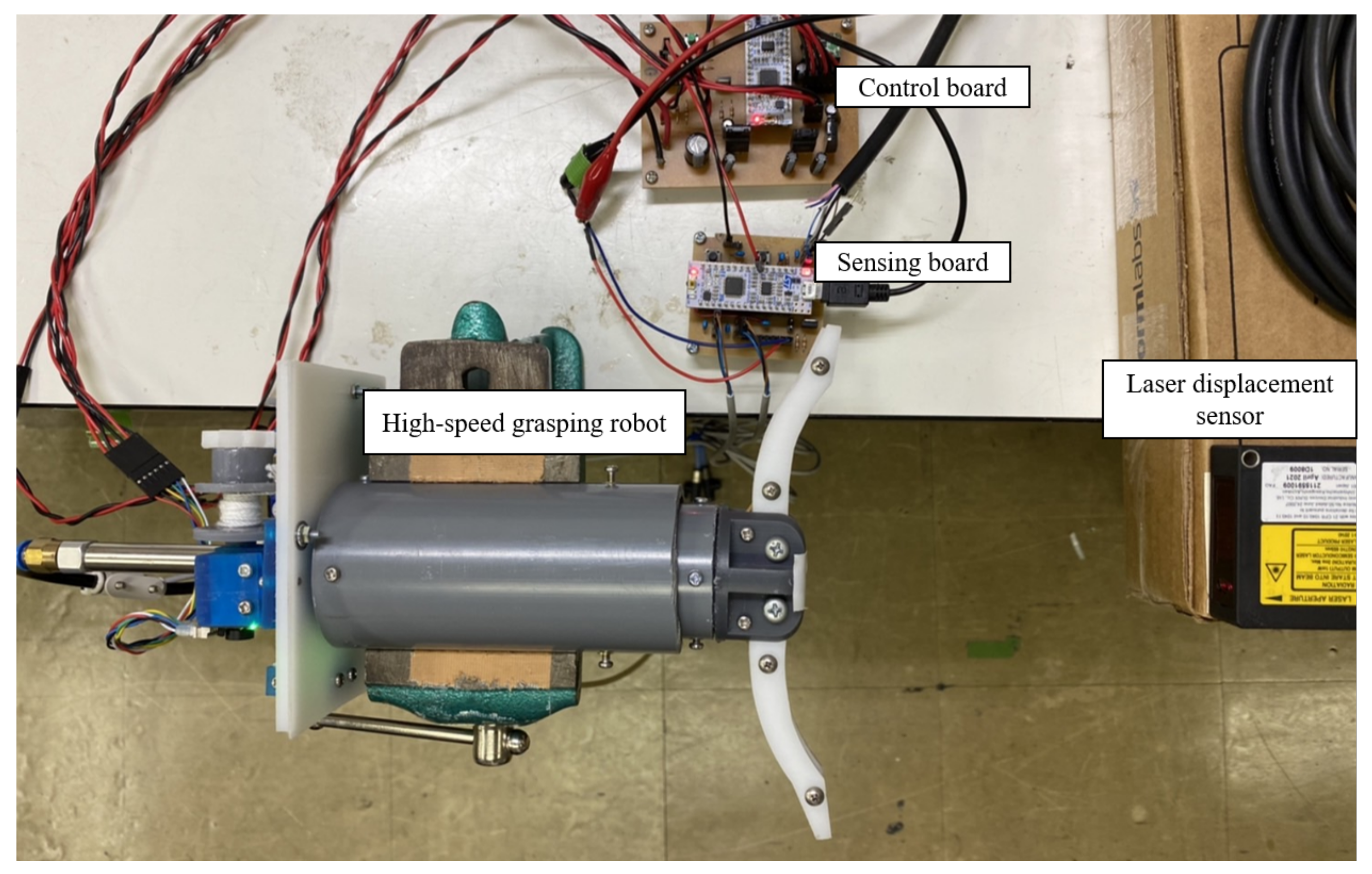
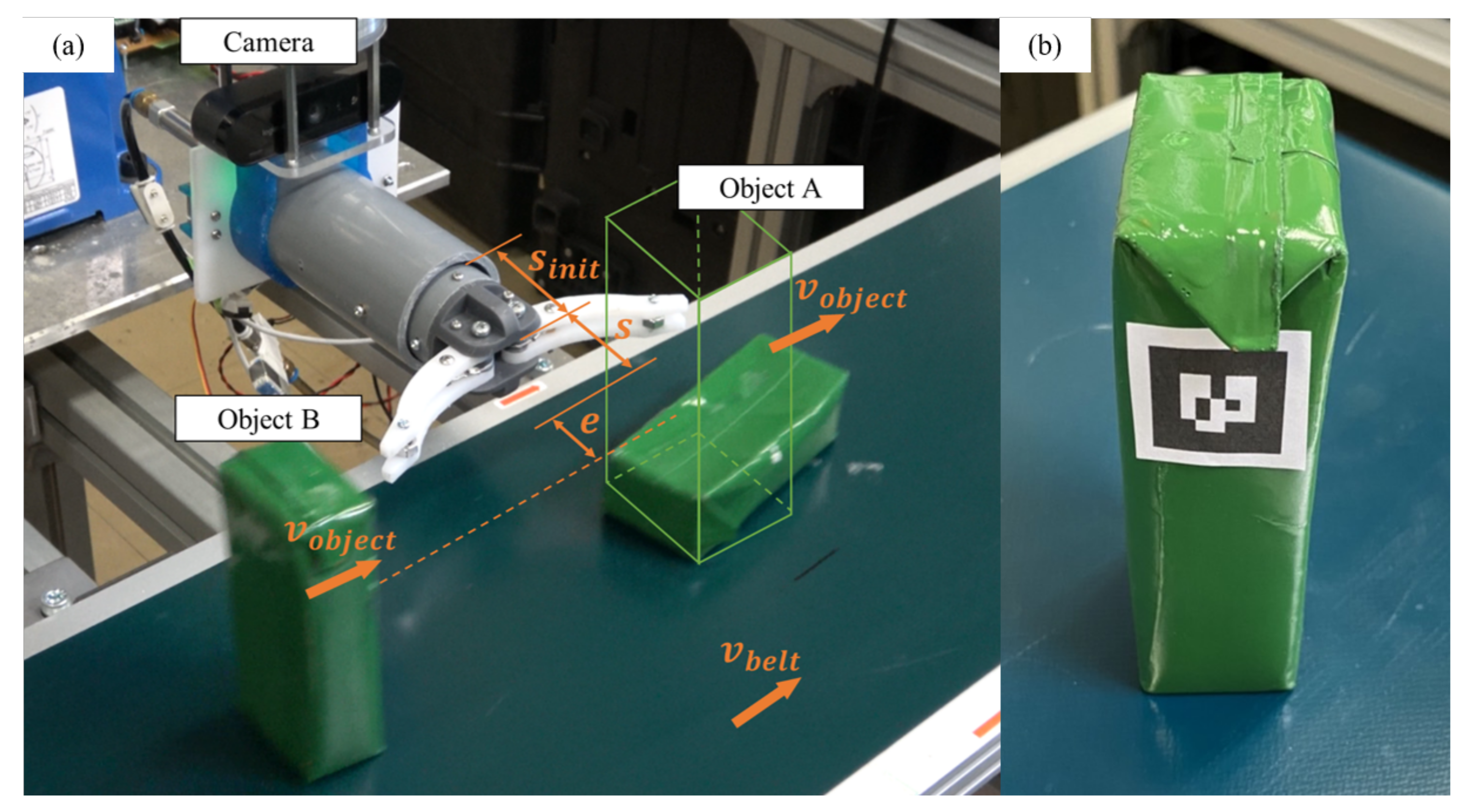
4.1. Experimental Setup

The experimental set up of the high-speed grasping robot is explained in this section. CJ2B10-60 (SMC) is used for the pneumatic cylinder of this robot. The inner diameter of the pneumatic cylinder is 10 mm, and the stroke of the cylinder rod is 60 mm. The maximum movement of the arm is set to 45 mm. A solenoid valve SY3120-C6 (SMC) with a response time of 10 ms is used for opening and closing the port of the air valve. The air compressor AC461X (Makita) is used for moving the pneumatic cylinder. The mass of the developed robot is 1.3 kg. The mass of the arm is 0.2 kg. The photo of the developed brake mechanism is shown in Figure 5, where ADA-3992 (Adafruit) is used as the solenoid with a 24 V power supply. In order to maintain the grasping state, the power has to be continuously supplied to the solenoid.
However, if the solenoid is switched on continuously for a long time, the solenoid will crush due to overheating. To avoid such overheating, the claw is implemented together with the ratchet gear. To maintain the grasping state, a lever is also attached behind the solenoid rod, and the servo motor pushes the lever to keep the claw engaged with the ratchet gear. This maintains the grasping state continuously without overheating. The SG-90 (Tower Pro) is used as the servo motor.
The positioning accuracy of the grasping position is determined by the number of fractions of the ratchet gears and is adjustable with an accuracy of 2.5 mm. Table 2 shows the specifications of the developed robot system. The acceleration of the robot is 15 gravity acceleration under the configuration of the robot and Equations (1)–(9).
Figure 6 shows the experimental environment for measuring the response times and so forth. The closing time of the robot is measured with a laser displacement sensor (Panasonic HL-G112-A-C5). The control board drives the robot and sends trigger signal for starting to measure the distance up to tip of the arm simultaneously. The sensing board measures the output signal from the laser displacement sensor as soon as it receives the signal from the control board.

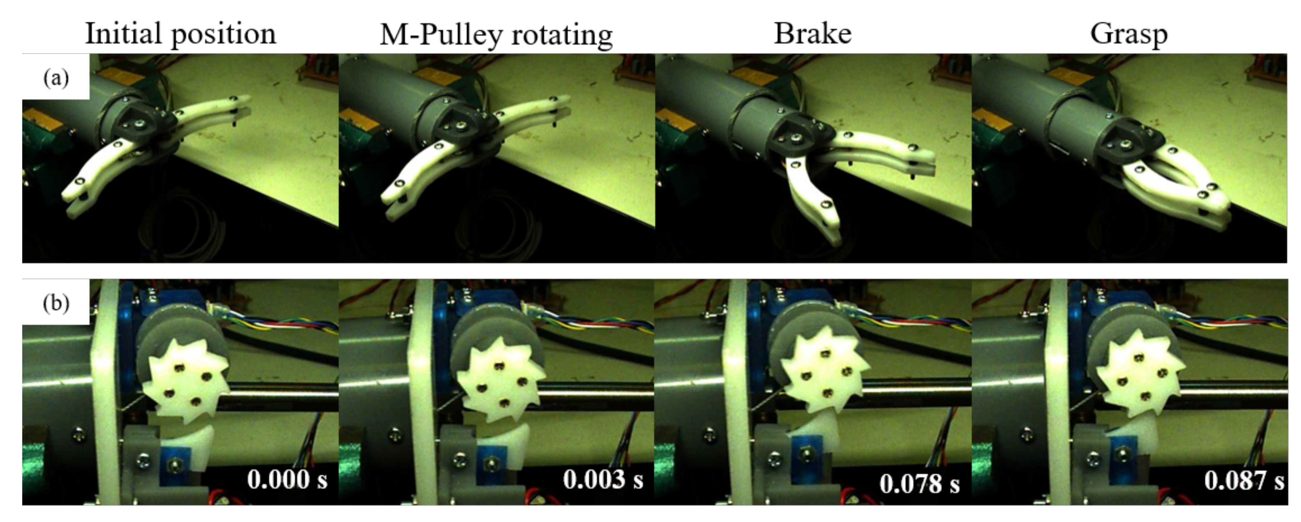
4.2. Evaluation of the Developed High-Speed Grasping Robot Model

We evaluate the dynamic characteristics of the developed high-speed grasping robot model using the equations obtained in Section 3. MATLAB R2020a is used for this simulation. Figure 7 shows the simulation results of the velocity (Figure 7a) and movement of the arm (Figure 7b) under the model where the gripper part is removed as shown in Figure 7c. In this simulation, the sonic conductance values C c and C d are changed as shown in the table given in the figure.
When the sonic conductance is extremely large, the equation of motion results in Equation (6), and the velocity is the largest. This is because when the sonic conductance increases, the pressures P c and P d applied at both sides of the piston of the pneumatic cylinder are always constant and equal to the given pressure. This tendency guarantees that the simulation is valid. We can see the tendency of the time for arm movement from Figure 7b where the condition leading to high-speed action makes the reaching time shorter as expected.
Figure 8 shows a comparison between the simulation and experimental results (Figure 8a) under the model where the gripper part is included as shown in Figure 8b, where the grasping position is set up to 0.045 m, C c and C d are 0.15 × 10 8 m 3 / ( s · Pa ) , the viscous friction coefficient for linear motion c l is 3 N · s/m and the viscous friction coefficient for rotation c r is 0.0 N · m · s .
One remark is that there is a nice coincidence between simulation and experiment, including two turning points at t = 0.05 s and at t = 0.08 s as shown in Figure 8a by changing the sonic conductance C c and C d ( C c = C d ) only. For the other parameters, we used the parameters listed in the specifications of each component. This means that the developed simulation model is valid and includes the basic dynamic characteristics that the developed high-speed grasping robot has.

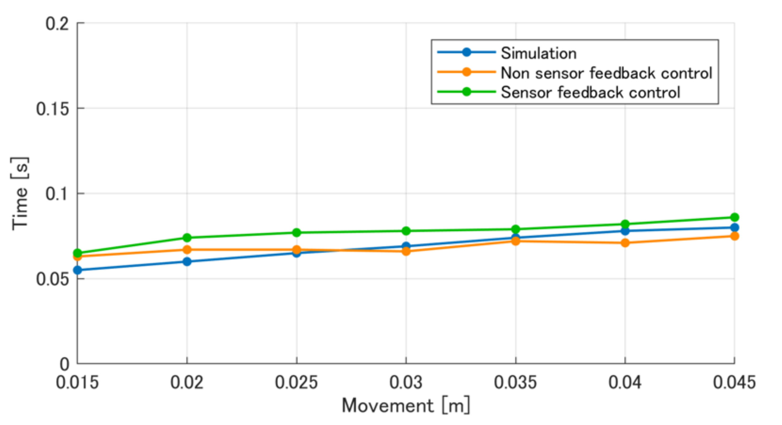
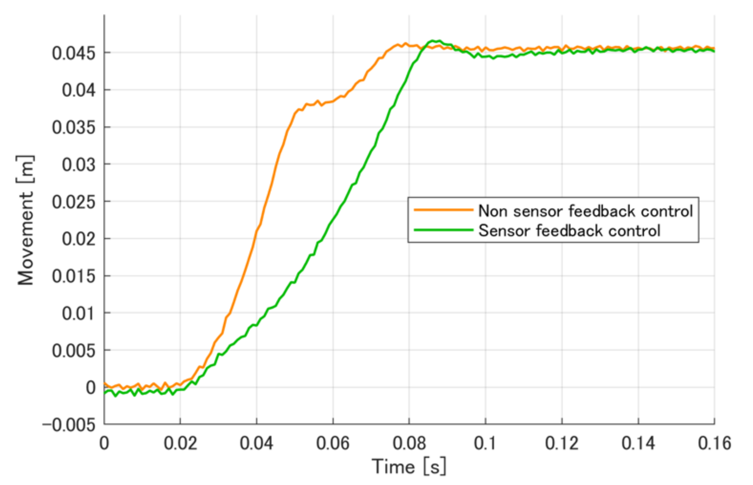
4.3. Verification of the Sensor Feedback Control of the High-Speed Grasping Robot

The developed robot has two methods to adjust the grasping position. One is to adjust the grasping position of the robot in advance by adjusting the length of the blue wire, and the other is to adjust the length of the blue wire by sensor feedback control of the grasping position of the gripper.
Therefore, there are two types of arm trajectory with respect to time, one for fixing the length of the blue wire (non-sensor feedback control) and the other for sensor feedback control by adjusting the length of the blue wire (sensor feedback control). The starting point of the grasping motion is set to the initial position shown in Figure 2, and the operating time is measured when the robot completely grasps an object.
Figure 9 shows the experimental results with the trajectory of the end point of arm when the arm moves to 0.045 m. The results show that, for up to 0.03 s, the robot trajectories are similar with respect to time for both the non-sensor feedback control and the sensor feedback control.
This means that, in both methods, it takes 0.03 s until the two stoppers make contact with each other and begin to increase the tension. After 0.03 s, the arm position of the sensor feedback control is slower than that of the non-sensor feedback control. The reason is possibly because we are considering the braking time for fixing the blue wire as negligible.
Simply speaking, it is difficult for the sensor feedback control to quickly stop the blue wire when starting the grasping motion, while non-sensor feedback control starts the grasping motion immediately after colliding with the two stoppers.
Figure 10 shows both the simulation and experimental results for the time to move up to the grasping position where the arm movement is set to 0.015–0.045 m and measurements are taken at 5 mm intervals. From these experiments, it can be seen that the simulation non-sensor feedback control and sensor feedback control have almost the same approach time and tendency with respect to movement, while the sensor feedback control takes a slightly longer time compared with the non-sensor feedback control.
While Figure 9 focuses on the approach phase only, Figure 11 shows the response characteristics of the robot for both the approach and release phases where the approach and release times start at t = 0 s and t = 0.15 s, respectively, and the same cycle is repeated at t = 0.50 s and 0.65 s, respectively. We set up the target movements with 0.045 m for the first trial (0 < t < 0.5 s) and the second trial (0.5 ≤ t < 0.8 s) with 0.02 m, respectively, so that we can observe the different behaviors between non-sensor feedback control and sensor feedback control, respectively.
An interesting behavior is that the times leading to both approaching and releasing are almost same between non-sensor feedback control and sensor feedback control, respectively, for the first trial, while the times leading to both approaching and releasing are very different between non-sensor feedback control and sensor feedback control, respectively, for the second trial. We note that the robot arm reaching position cannot be changed for non-sensor feedback control once the action starts. This is the reason why the response characteristics are the same in the first and the second trials for non-sensor feedback control.
On the other hand, the response characteristics are different in the first and the second trials for sensor feedback control. This is because the robot changes the target position according to the distance information up to the object for sensor feedback control. In addition to this advantage, there is another advantage for sensor feedback control, where the time leading to both approaching and releasing is shorter by 20 % (0.2 s) compared with that for non-sensor feedback control (0.25 s).
Once again, in the case for objects placed with various distances, the sensor feedback control is more advantageous in flexibility compared with the non feedback control, while additional mechanisms, such as a brake and base actuator, are necessary.
Figure 12 shows continuous photos where the upper photos show the grasping motion captured by the high-speed camera (Baumer VCXU-02 891 fps) and the lower photos show the braking motion captured by the high-speed camera. From Figure 12, we can also see that the grasping motion does not start until the pulley based on the motor (M-Pulley) starts rotating, and the grasping motion starts after the M-Pulley starts rotating and before braking.

4.4. Experiment to Grasp Moving Objects on a Belt Conveyor

In this section, we discuss the performance for misaligned objects through a belt conveyor. We also confirm the adaptability for the high-speed grasping of an object on a belt conveyor, which means changing the pose of the target object when the target object moves quickly. Figure 13 shows an overview of the experimental system. An ArUco marker is attached to the target object so that the camera (logicool C1000eR 120 fps) mounted on the root of the robot can detect it and estimate the position of the object.
The mass of the target objects is 0.2 kg, and this object is moved by a belt conveyor (MISUMI SVKA-250-850-25-S200-IM). When target objects move into the grasping area, the system estimates the grasping position of the robot and begins the grasping action toward the object. This operation is performed for three misaligned objects continuously, and the stroke s of the robot is set to 30 mm. The misalignment e of the object that can be grasped is ±15 mm. s i n i t is the initial position of the robot.
An example of the experimental results is shown in Figure 14 with continuous grasping and laying down of the moving objects. Under these conditions, the object was captured with a success rate of 30 / 30 trials where a 200 mL drink pack was used as the object (Supplemental video is available at Video S1).
Figure 15 shows the success rate for the continuous grasping of moving objects where the 330 mL pet bottles with different amount of water were used for experiments to observe how the success rate changes depending upon the mass of the object.
For comparison purposes, the success rate for the experiment using a 200 mL drink pack is also shown in Figure 15a where the success rate of grasping a 200 mL drink pack was 100% (30/30 trials). Figure 15b shows the success rate of grasping objects for various amount of water from zero to 300 g. From Figure 15b, we can see the following tendency of low success rates for both a low amount of water and a large amount of water.
Figure 15b includes the experimental results under two different conditions where experiment was conducted without any wrapping of packing material and the other experiment was performed with wrapping of packing material, including many small air cushions. To our surprise, the success rate demonstrated a great difference between the conditions of with and without the wrapping of packing materials. An interesting behavior regarding the condition of no wrapping is that there was a maximum success rate for the mass of water of 100 g.
This means that the success rate was diminished for either a small mass of water or a large mass of water. Another interesting tendency is that, under no wrapping, the maximum success rate was only 30% for a mass of water of 100 g, while we found 77% for the mass of water of 50 g with wrapping. We believe that a high success rate is related to an appropriate combination considering the properties of the object (shape, weight and compliance), the surface friction and actuator power.

5. Conclusions

In this paper, we discussed the modeling and experiments of a newly developed high-speed adjustable robot controlled by a pneumatic actuator. The robot is composed of a pneumatic actuator, two grippers and two wires, where one connects the stopper and the gripper joints with a spring, and the other wire connects the stopper and a pulley connected to a motor with a brake for locking the end of the wires. Each stopper includes a hole at the center so that the wire may freely move through the stopper.
This simple mechanism contributes to transferring the arm-translational energy produced by the pneumatic actuator into the gripper rotational energy without a loss of energy. The role of the brake is to fix the length of the stopper so that the target object may be captured appropriately. We demonstrated that the simulation coincided with the experimental results utilizing the developed robot system.
Through our experiments, we confirmed that the developed high-speed grasping robot could grasp continuously moving objects with a gap of ±15 mm at 300 mm/s.
In particular, the success rate of grasping a 200 mL drink pack was 100% (30/30 trials) under the best tuning conditions. The high success rate was obtained only by an appropriate combination with the properties of the object (the shape, weight and compliance), the surface friction and the actuator power.
For future works, in order to improve the accuracy of the grasping position, we will develop a mechanism to absorb the reaction force generated during the arm acceleration and to absorb the shock generated during the arm retraction. We will also aim to improve our grasping ability so that we can grasp various items, such as daily necessities and parts moving in a production line. We will also apply a pneumatic actuator to control a cell in a micro fluid channel by using the model used in this work.
Furthermore, there is a work where liquid and cells were mixed in an on-chip micro mixer combined with an air chamber [22]. The advantage of using an air chamber is to generate a virtual actuator near the swirling chamber. By changing the pressure in the air chamber, we could change the dynamics of the chamber wall, which would contribute to changing the swirling motion of a liquid together with cells. We would like to apply the theory used in this work for controlling the pressure in an air chamber, particularly for the simulation model.

Supplementary Materials

Supplementary materials is available at https://www.mdpi.com/article/10.3390/robotics11010027/s1, Video S1: Demonstration of high-speed grasping motion.

Author Contributions

Conceptualization, K.O., R.I. and M.K.; methodology, K.O., R.I. and M.K.; system implementation, K.O., R.I.; validation, K.O., R.I. and M.K.; formal analysis, K.O., R.I. and M.K.; investigation, K.O., R.I. and M.K.; writing—original draft preparation, K.O., R.I. and M.K.; writing—review and editing, K.O., R.I. and M.K.; visualization, K.O., R.I. and M.K.; supervision, K.O.; project administration, M.K. All authors have read and agreed to the published version of the manuscript.

Funding

This work was partially supported by JSPS KAKENHI Grant No. 19H00749 and 20K20987.

Institutional Review Board Statement

Not applicable.

Informed Consent Statement

Not applicable.

Data Availability Statement

Not applicable.

Conflicts of Interest

The authors declare no conflict of interest.

References

  1. Namiki, A.; Imai, Y.; Ishikawa, M.; Kaneko, M. Development of a High-speed Multifingered Hand System and Its Application to Catching. In Proceedings of the 2003 IEEE/RSJ International Conference on Intelligent Robots and Systems (IROS), Las Vegas, NV, USA, 27–31 October 2003; pp. 2666–2671. [Google Scholar]
  2. Namiki, A.; Imai, Y.; Ishikawa, M.; Kaneko, M.; Kameda, H.; Koyama, J. Dynamic Catching Using a Ultra-High-Speed Multifingerd Hand System. In Proceedings of the 2003 IEEE International Conference on Robotics and Automation (ICRA) Video Proceedings, Abstracts & References, Taipei, Taiwan, 13 September 2003; pp. 28–29. [Google Scholar]
  3. Kizaki, T.; Namiki, A. Two Ball Juggling with High-Speed Hand-Arm and High-Speed Vision System. In Proceedings of the 2012 IEEE International Conference on Robotics and Automation (ICRA), Saint Paul, MN, USA, 14–18 May 2012; pp. 1372–1377. [Google Scholar]
  4. Namiki, A.; Itoi, N. Ball Catching in Kendama Game by Estimating Grasp Conditions Based on a High-Speed Vision System and Tactile Sensors. In Proceedings of the 2014 IEEE-RAS International Conference on Humanoid Robots (Humanoids), Madrid, Spain, 18–20 November 2014; pp. 634–639. [Google Scholar]
  5. Yamakawa, Y.; Namiki, A.; Ishikawa, M. Simple Model and Deformation Control of a Flexible Rope using Constant, High-Speed Motion of a Robot Arm. In Proceedings of the 2012 IEEE International Conference on Robotics and Automation (ICRA), Saint Paul, MN, USA, 14–18 May 2012; pp. 2249–2254. [Google Scholar]
  6. Takaki, T.; Omata, T. High Performance Anthropomorpic Prosthetic Hand with Grasp force Magnification Mechanism. In Proceedings of the 2009 IEEE International Conference on Robotics and Automation (ICRA), Kobe, Japan, 12–17 May 2009; pp. 1697–1703. [Google Scholar]
  7. Takayama, T.; Chiba, Y.; Omata, T. Tokyo-TECH 100N Hand: Three-fingered eight-DOF hand with a force-magnification mechanism. In Proceedings of the 2009 IEEE International Conference on Robotics and Automation (ICRA), Kobe, Japan, 12–17 May 2009; pp. 593–598. [Google Scholar]
  8. Koyama, K.; Shimojo, M.; Senno, T.; Ishikawa, M. High-Speed High-Precision Proximity Sensor for Detection of Tilt, Distance and Contact. IEEE Robot. Autom. Lett. 2018, 3, 3224–3231. [Google Scholar] [CrossRef]
  9. Chen, C.; Lan, C. An Accurate Force Regulation Mechanism for High-Speed Handling of Fragile Objects Using Pneumatic Grippers. IEEE Trans. Autom. Sci. Eng. 2017, 15, 1600–1608. [Google Scholar] [CrossRef]
  10. Thuruthel, T.G.; Abidi, S.H.; Cianchetti, M.; Laschi, C.; Falotico, E. A bistable soft gripper with mechanically embedded sensing and actuation for fast closed-loop grasping. arXiv 2019, arXiv:1902.04896v1. [Google Scholar]
  11. Sun, J.; Tighe, B.; Zhao, J. Tuning the Energy Landscape of Soft Robots for Fast and Strong Motion. In Proceedings of the 2020 IEEE International Conference on Robotics and Automation (ICRA), Paris, France, 31 May–31 August 2020; pp. 10082–10088. [Google Scholar]
  12. Higashimori, M.; Kaneko, M.; Namiki, A.; Ishikawa, M. Design of the 100G Capturing Robot Based on Dynamic Preshaping. Int. J. Robot. Res. 2005, 24, 743–753. [Google Scholar] [CrossRef]
  13. O’Brien, K.W.; Xu, P.A.; Levine, D.J.; Aubin, C.A.; Yang, H.H.; Xiao, M.F.; Wiesner, L.W.; Shepherd, R.F. Elastomeric passive transmission for autonomous force-velocity adaptation applied to 3D-printed prosthetics. Sci. Robot. 2018, 3, eaau5543. [Google Scholar] [CrossRef] [PubMed] [Green Version]
  14. Hirai, Y.; Suzuki, Y.; Tsuji, T.; Watanabe, T. High-speed and Intelligent Pre-grasp Motion by a Robotic Hand Equipped with Hierarchical Proximity Sensors. In Proceedings of the 2018 IEEE/RSJ International Conference on Intelligent Robots and Systems (IROS), Madrid, Spain, 1–5 October 2018; pp. 7424–7431. [Google Scholar]
  15. Li, J.; Zhang, R.; Mou, L.; Andrade, M.J.D.; Hu, X.; Yu., K.; Sun, J.; Jia, T.; Dou, Y.; Chen, H.; et al. Photothermal Bimorph Actuators with In-Built Cooler for Light Mills, Frequency Switches, and Soft Robots. Adv. Funct. Mater. 2019, 29, 1808995. [Google Scholar] [CrossRef]
  16. Andronas, D.; Xythalis, S.; Karagiannis, P.; Michalos, G.; Makris, S. Robot gripper with high speed, in-hand object manipulation capabilities. Procedia CIRP 2020, 97, 482–486. [Google Scholar] [CrossRef]
  17. Yamanaka, Y.; Katagiri, S.; Nabae, H.; Suzumori, K.; Endo, G. Development of a Food Handling Soft Robot Hand Considering a High-speed Pick-and-place Task. In Proceedings of the 2020 IEEE/SICE International Symposium on System Integration (SII), Honolulu, HI, USA, 12–15 January 2020; pp. 87–92. [Google Scholar]
  18. Kang, T.; Yi, J.-B.; Song, D.; Yi, S.-J. High-Speed Autonomous Robotic Assembly Using In-Hand Manipulation and Re-Grasping. Appl. Sci. 2021, 11, 37. [Google Scholar] [CrossRef]
  19. Yamakawa, Y.; Katsuki, Y.; Watanabe, Y.; Ishikawa, M. Development of a High-Speed, Low-Latency Telemanipulated Robot Hand System. Robotics 2021, 10, 41. [Google Scholar] [CrossRef]
  20. Iwazawa, R.; Ohara, K.; Kaneko, M. Development of high-speed gripper with closing and releasing capability. In Proceedings of the 2021 IEEE/SICE International Symposium on System Integration (SII), Iwaki, Fukushima, 11–14 January 2021; pp. 619–622. [Google Scholar]
  21. Chen, S.; Youn, C.; Kagawa, T.; Cai, M. Transmission and Consumption of Air Power in Pneumatic System. Energy Power Eng. 2014, 6, 487–495. [Google Scholar] [CrossRef] [Green Version]
  22. Takayama, T.; Kaneko, M.; Tsai, C.-H.D. On-Chip Micro Mixer Driven by Elastic Wall with Virtual Actuator. Micromachines 2021, 12, 217. [Google Scholar] [CrossRef] [PubMed]
Figure 1. Capturing patterns of the developed high-speed grasping robot. (a) Successful grasping. (b) Grasp failure due to the collision problem. (c) Grasp failure due to the geometric problem.
Robotics 11 00027 g001
Figure 2. Design concept of a high-speed grasping robot with the braking mechanism.
Robotics 11 00027 g002
Figure 3. Modeling of the driving part.
Robotics 11 00027 g003
Figure 4. Modeling of the gripper part.
Robotics 11 00027 g004
Figure 5. Specifications of the high-speed grasping robot.
Robotics 11 00027 g005
Figure 6. Experimental environment for verification of the grasping time.
Robotics 11 00027 g006
Figure 7. Simulation results when the sonic conductance is increased: (a) the simulation results of the velocity, (b) the simulation results of the movement and (c) the model where the gripper part is removed.
Robotics 11 00027 g007
Figure 8. Comparison of the simulation results and experimental results: (a) the simulation and experimental results of the movement and (b) the model where the gripper part is included.
Robotics 11 00027 g008
Figure 9. The response characteristics of the robot approach time.
Robotics 11 00027 g009
Figure 10. Experimental results for the robot approach time.
Robotics 11 00027 g010
Figure 11. The response characteristics of the robot approach and release times.
Robotics 11 00027 g011
Figure 12. Continuous photos: (a) grasping motion and (b) brake action when the arm movement amount is 45 mm.
Robotics 11 00027 g012
Figure 13. Experimental setup of the continuous grasping of moving objects: (a) system configuration and (b) target objects (200 mL drink pack). v o b j e c t and v b e l t are the velocity of the object and the velocity of the belt conveyor, respectively. Experiments were performed with a v b e l t speed of 300 mm/s.
Robotics 11 00027 g013
Figure 14. An example of the experimental results of grasping and laying down moving objects with misalignment: (a) grasping motion and (b) laying down motion.
Robotics 11 00027 g014
Figure 15. Experimental results of grasping moving objects: (a) 200 mL drink pack and (b) 330 mL pet bottles. The definition of the success is when the robot system can successfully grasp the object.
Robotics 11 00027 g015
Table 1. Specification of the gripper parameters.
ParameterValue
LLength between A and B20 mm
rPulley radius6 mm
α Angle between CA and AB 17 . 5
β Angle between BA and AD 13 . 5
F k Spring reaction force1.67 N
JMoment of inertia of gripper24.2 kg · mm2
Table 2. Specifications of the high-speed grasping robot.
ParameterValue
Mass of the high-speed grasping robot1.3 kg
Mass of the arm0.2 kg
Supply pressure0.5 MPa
Acceleration15 × 9.8 m/s2
Arm stroke15–45 mm
Positioning accuracy of grasping position2.5 mm
Publisher’s Note: MDPI stays neutral with regard to jurisdictional claims in published maps and institutional affiliations.

