Article

Petrographic Record and Conditions of Expansive Hydration of Anhydrite in the Recent Weathering Zone at the Abandoned Dingwall Gypsum Quarry, Nova Scotia, Canada

1
Faculty of Geology, University of Warsaw, ul. Żwirki i Wigury 93, 02-089 Warszawa, Poland
2
Deutsches Gipsmuseum und Karstwanderweg e.V., Düna 91, D-37520 Osterode, Germany
*
Authors to whom correspondence should be addressed.
Minerals 2022, 12(1), 58; https://doi.org/10.3390/min12010058
Submission received: 10 November 2021 / Revised: 19 December 2021 / Accepted: 20 December 2021 / Published: 31 December 2021

Abstract

:
In the Dingwall gypsum quarry in Nova Scotia, Canada, operating in 1933–1955, the bedrock anhydrite deposits of the Carboniferous Windsor Group have been uncovered from beneath the secondary gypsum beds of the extracted raw material. The anhydrite has been subjected to weathering undergoing hydration (gypsification), transforming into secondary gypsum due to contact with water of meteoric derivation. The ongoing gypsification is associated with a volume increase and deformation of the quarry bottom. The surface layer of the rocks is locally split from the substrate and raised, forming spectacular hydration relief. It shows numerous domes, ridges and tepee structures with empty internal chambers, some of which represent unique hydration caves (swelling caves, Quellungshöhlen). The petrographic structure of the weathering zone has been revealed by macro- and microscopic observations. It was recognized that gypsification commonly starts from a developing network of tiny fractures penetrating massive anhydrite. The gypsification advances from the fractures towards the interior of the anhydrite rocks, which are subdivided into blocks or nodules similar to corestones. Characteristic zones can be recognized at the contact of the anhydrite and the secondary gypsum: (1) massive and/or microporous anhydrite, (2) anhydrite penetrated by tiny gypsum veinlets separating the disturbed crystals and their fragments (commonly along cleavage planes), (3) gypsum with scattered anhydrite relics, and (4) secondary gypsum. The secondary gypsum crystals grow both by replacement and displacement, and also as cement. Displacive growth, evidenced by abundant deformation of the fragmented anhydrite crystals, is the direct cause of the volume increase. Crystallization pressure exerted by gypsum growth is thought to be the main factor generating volume increase and, consequently, also the formation of new fractures allowing water access to “fresh” massive anhydrite and thus accelerating its further hydration. The expansive hydration is taking place within temperature range from 0 to ~30 °C in which the solubility of gypsum is lower than that of anhydrite. In such conditions, dissolving anhydrite yields a solution supersaturated with gypsum and the dissolution of anhydrite is simultaneous with in situ replacive gypsum crystallization. Accompanying displacive growth leads to volume increase in the poorly confined environment of the weathering zone that is susceptible to upward expansion.

1. Introduction

Hydration of mineral anhydrite (CaSO4) leading to crystallization of gypsum (CaSO4∙2H2O) is a common reaction observed both in the weathering zone and deeper subsurface [1]. This process has a specific character due to the potential volume changes that accompany mineral transformation. Theoretically, during this process (gypsification of anhydrite) the volume can decrease by 9% in the closed system and increase by 62.7% in the open system when the water comes from the outside [2].
In natural environments, the recorded volume changes related to gypsification of anhydrite are variable. The volume changes may not take place at all or be negligible and unnoticeable [3,4], and such a case is more common than volume increase ([5], with references therein). Anhydrite beds, and gypsum beds which are the product of their hydration, then retain the same thickness [6,7,8]. Moreover, such beds do not show the deformations which are expected in the process of volume increase [3,5,6,8,9] (p. 10).
In the other cases, it has been observed that the secondary gypsum has a greater volume than the anhydrite from which it was formed. Commonly, the estimated volume increase is less than the theoretical value of 62.7%, e.g., by 26% [10] (p. 37, Figure 9), or by 50% [11]. Amadeus W. Grabau concluded that during the transition of anhydrite to gypsum due to hydration the volume may increase by 30% to 50% [12] (pp. 177, 537) and [13] (p. 359).
The reasons why there is no increase in volume in one case and on a variable scale in the other are not quite clear. In addition, the mechanisms of volume change operating on a microscopic scale are not well recognized and understood.
The lack of or smaller volume increase than theoretically predicted is commonly explained by the escape of excess calcium sulphate derived from the dissolution of anhydrite out of the place of dissolution (e.g., [14,15]). In such a case, gypsum crystallization may occur partially or even completely outside the system [3,5].
The other reason for smaller volume expansion is the occurrence of hydration in a confined environment deep under the Earth’s surface. At a depth of over 60–75 m ([1], and references therein) lithostatic pressure balances and surpasses the pressure induced by anhydrite hydration leading to “swelling” and is able to inhibit or stop this process. Hydration of anhydrite is entirely impossible above a certain temperature (>42–60 °C, for the pure water, [16]) in the thermodynamic conditions in which anhydrite is stable and gypsum unstable, and under the Earth’s surface there is a certain depth below which this reaction is unlikely, mainly because of the too high temperature [17].
Volume increase related to gypsification of anhydrite is recorded not only in the ancient rocks. In some places the expansive hydration is manifested nowadays allowing study of its rate and course [18,19,20,21]. It is particularly rapid in anhydrite-bearing clay rocks [20]. The most remarkable are railway and road tunnels and viaducts situated on the anhydrite-bearing substrate which have a tendency to heave. The heave of some tunnel floors is very rapid [19,22,23] and continues for many years. Recently, even more destructive large scale heave, causing the catastrophic fracturing of buildings and roads, has taken place in the areas of some cities (Staufen im Breisgau, Böblingen, Rudersberg in Germany, and Lochwiller in France) where geothermal installations disturbed the hydrological system in the deeper subsurface containing the anhydrites [24,25]. In spite of many studies, these heave processes are difficult to predict and practically impossible to stop by currently known engineering methods.
There are also anhydrite occurrences undergoing more or less pronounced expansive hydration directly at the surface—in the weathering zone (e.g., [26]). The weathering zone is a place that has a practically unlimited inflow of water of the atmospheric derivation supporting the hydration process, except for that of polar regions, where the water is frozen and trapped in the permafrost (Shearman in [27]) (p. 291) [28]. A less confined rock and soil environment of this zone is susceptible to expansion, however, for some reasons, such an expansion does not always take place.
In some rare anhydrite outcrops an increase in volume is manifested by smaller scale morphological forms that are visible on the surface as domes and pressure ridges with the internal caverns below detached and an uplifted surface layer of the rocks [18] ([21], with references therein). Some of the caverns are large enough to allow an adult person to enter, and as such they represent caves. The peculiar origin of these caves makes them unique speleological objects; they are known as hydration caves (or swelling caves, German: Quellungshöhlen). Large groups of such hydration caverns and caves creating peculiar landscapes on the weathering anhydrite rocks are so far recorded in only a few places on Earth [21]. They are known from two natural sites: near Walkenried in Germany [18,29], and on the Alebastrovyye Islands in Russia [30], and from two abandoned gypsum quarries: at Pisky in Ukraine [31,32] and Dingwall in Canada (Figure 1) [29,33,34,35]. The latter site is the subject of authors’ investigations.
The Dingwall site offers an excellent opportunity to study the processes of anhydrite weathering and expansive hydration both at the macro- and microscale. Previous studies in this quarry have focused mainly on the morphology and morphometric aspects of the karst forms, like karren [36], and of the hydration forms. The petrological features of the anhydrite hydration (gypsification of anhydrite), fundamental for the understanding of the process on the microscale level, were not studied so far, and the present paper focuses on this issue.
Although previous petrological studies of the anhydrite weathering zones, both the ancient, the sub-fossil and the modern ones, were led by many authors (e.g., [1,15,28,37]) only a few such studies documented recently undergoing expansive hydration [18,31,36,38]. The current work supplements the knowledge on this subject and is an attempt of disclosure of the poorly known mechanisms and conditions of the volume expansion during the hydration of anhydrite. Basing on detailed macro- and microscopic petrographic investigations, we restore the processes of expansive gypsification presenting model interpretations of microstructural and mineralogical evolution of the weathering zone. We also attempt to characterize the environmental conditions responsible for the advance of the expansive gypsification at this site and to recognize basic factors which drive and inhibit that process and control the degree of volume increase.
Figure 1. Location of the studied abandoned gypsum quarry at Dingwall (a) and photographs of the site (bf); b–central field of the quarry seen from the north; (c)–exemplary hydration dome along with internal void and with Firouz Vladi next to it; (d)–bottom of the quarry (see b) with spheroidal fractures related to spheroidal weathering (similar to cannonball structures from New Brunswick [39]), note layering (marked by dotted yellow line) and hydration domes with cavern or cave in the background; (e)–bottom of the quarry in eastern field showing regular joint system (marked by red dotted lines) and hydration forms; (f)–sinkholes (schlottenkarren; marked by red arrows) seen in the quarry wall in central field.
Minerals 12 00058 g001

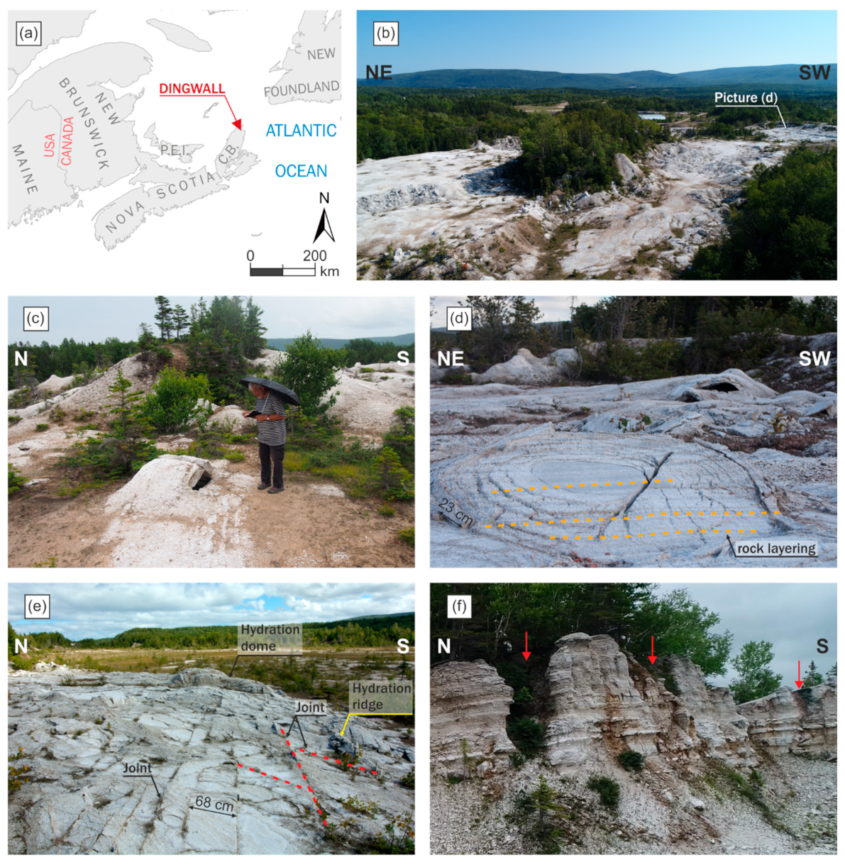
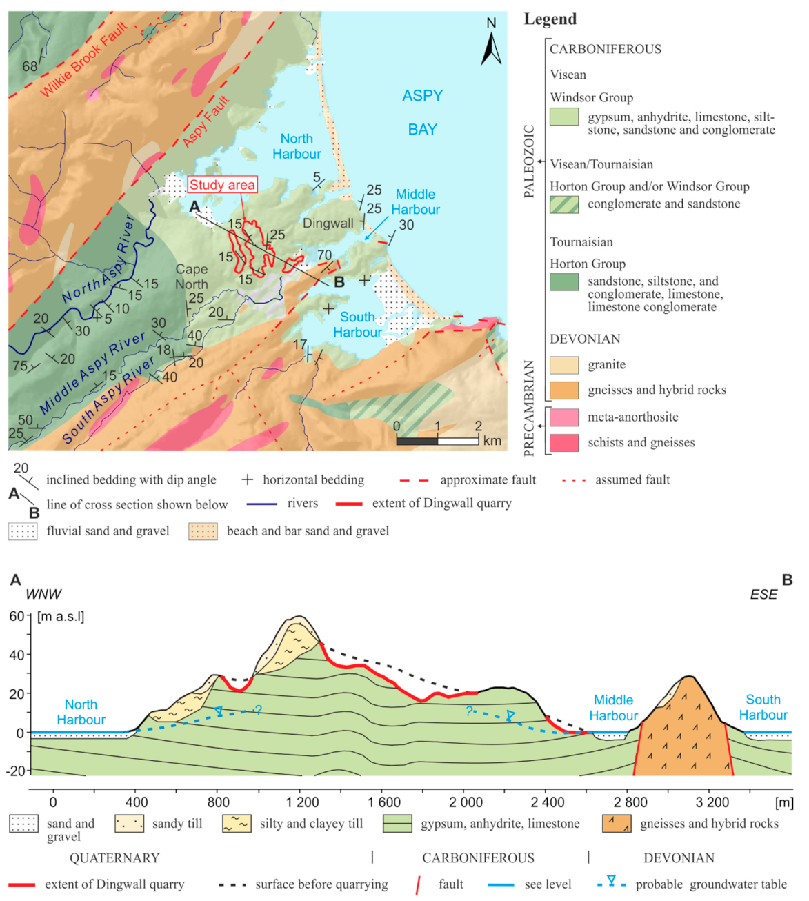
2. Climate and Geology of Studied Area

Dingwall in the province Nova Scotia has the temperate, cold climate (Dfb, classification according to Köppen and Geiger [40]. According to data from Dalem Lake, 70 km south of Dingwall, the average annual precipitation is 1346 mm with a greater intensity in winter, while the average temperature is +6.7 °C (minimum in February: −8.3 °C, maximum in August: +22.3 °C; [41]). Temperature fluctuations around 0 °C thus have a significant influence on the course of weathering. Snow cover can be quite thick in wintertime, reaching more than 2 m [42] and snow stays in some sinkholes until July [33].
In the quarry at Dingwall, which was opened in 1933 and has been closed since 1955, secondary gypsum occupying the upper part of the weathering profile over the bedrock of anhydrite rocks was exploited [43]. The anhydrite rocks exposed at the quarry bottom represent the lowest part of the Windsor Group, comprising Carboniferous (Mississippian, Visean) sediments of the Maritimes Basin in the Atlantic part of Canada (Figure 2) [44]. The Windsor Group is a “saline giant”; one of a few tens of Earth’s marine evaporate deposits attaining particularly large sizes [45]. It includes two main sequences containing five cycles (subzones), lettered from A (the oldest) to E (the youngest) [46]. The studied deposits belong to the lowest A cycle, representing the rapid marine transgression, and probably also to the B cycle [46,47,48,49]. They at least partly are secondary deposits derived from dehydration of gypsum which was originally deposited in the Maritimes Basin [45]. These evaporites overlie the clastic rocks of the Horton Group and slope north-east creating a depression underneath the Aspy Bay (Figure 2). Both formations are bounded to the northwest by the Aspy Fault (Figure 2 and Figure 3) [50] and from the southwest contact with older igneous and metamorphic rocks. The Windsor Group rocks present in the quarry were overlain by sandy and clayey Quaternary till (removed during exploitation), with a thickness of several to over a dozen meters, deposited during the last late Pleistocene Wisconsinan glaciation [51,52]. Gravels of igneous and metamorphic rocks derived from this till are found scattered at the bottom of the quarry.
The studied site contains a large number of hydration forms (77 documented forms of remarkable sizes, apart from many smaller forms) and the largest number of documented hydration caves (more than 40), including the largest known existing hydration cave, the Ramesh Cave [21]. It is the place with actively developing hydration relief noticed already in 1969 [53] and studied more systematically since 1990 [21,29,33,34,35].
Figure 3. Relief of the expansive hydration zone developing on the anhydrite bottom of the gypsum quarry at Dingwall (north part of the central field, Figure 2) with examples of gypsification zones (a–initial; b,c–advanced; d–mature) and rock samples typical of these zones. Content of gypsum in the rocks was determined by microscopic observation (a,d) and the method described by Ługowski et al. [54] (b,c); (a)–sample of anhydrite collected from central part of the spheroidal weathering (cannonball) structure (from point marked by red arrow); (b)–sample of gypsum-anhydrite rock from the detached elevated layer (from point marked by red arrow) forming ceiling of the hydration Ramesh Cave (authors, A.J., F.V., D.Ł., as scale on the right photo taken on 24 September 2018); (c)–sample of gypsum-anhydrite rock dug from depth of ca 70 cm at the boundary of the western range of extent of the hydration tepee with internal cave called “Personal Grotto” (from place marked by red arrow); photo taken on 28 August 2019; (d)–sample collected 6 m above bottom of the quarry (from place marked by red arrow). Signs on the upper right side of the photos of samples: arrow–upward direction relative to the quarry bottom, X–view on the surface cut parallel to the horizontal plane. Panoramic photography of the quarry was made by author (A.J.) in September 2018 with usage of Unmanned Aerial Vehicle.
Minerals 12 00058 g003aMinerals 12 00058 g003b

3. Terminology

The term structure was used for the macroscopic characteristics of the rock specimens and outcrops and means “the arrangement of the parts of a rock mass irrespective of scale, including spatial relationships between the parts, their relative size and shape and the internal features of the parts” [55] (p. 26). Rock structures were described using sample cuts and field observations. The description of structures was based on works concerning anhydrite rocks [56,57,58] and gypsum-anhydrite rocks [5,31,59,60,61].
The term fabric was used for microscopic observations to describe “the arrangement of crystals in a rock in terms of their sizes, shapes and crystallographic orientations” [62] (p. 565) (compare [63]). The anhydrite fabric was characterized based on the classification of Devonian anhydrite rocks from the Elk Point Basin in Canada [56], and supplemented by the work of Friedman [63], where the division of fabrics into equigranular and inequigranular was used. The description of the crystals was based on the classification of both gypsum and anhydrite, taking into account the shape and size of the crystals [60]. In addition, the description of fabrics types characteristic for inequigranular fabrics was used to refer to larger crystals within a fine-grained matrix [63].
The hydration of anhydrite is understood as a process of its transformation into secondary gypsum according to the reaction CaSO4 + 2H2O = CaSO4∙2H2O. The expression of that process in the geological record can be called gypsification of anhydrite when the gypsum under study is entirely the product of this process. According to Neuendorf et al. [64] (p. 289), gypsification means “development of, or conversion into, gypsum, e.g., the hydration of anhydrite”.
Gypsification of anhydrite is not a simple (volume by volume) replacement of anhydrite by gypsum, but is instead a more complex process, mainly because of the presence of pore spaces in the rocks. The expansive hydration of anhydrite can involve three basic mechanisms according to which newly formed gypsum crystals can gain space in the rock [31]: (1) in situ replacement of anhydrite by gypsum, or in other words replacive growth of gypsum; (2) growth of gypsum in pore spaces, i.e., cementation or growth as cement, known also as free growth, growth in open space (within pores); (3) displacement, or displacive growth of gypsum crystals, i.e., mechanical displacement of the surrounding anhydrite and/or gypsum crystals by surfaces of the newly growing gypsum crystals. Definitions of these terms and discussions of their physical meaning and of criteria of recognition are provided in many classical petrological publications [62,65,66,67,68,69].

4. Materials and Methods

4.1. Field Studies

Rock samples were collected during field trips to the Dingwall quarry in September 2018 and August 2019. Samples were taken from various parts of the anhydrite weathering zone, and particularly from the deformed part of the quarry bottom, documenting the most pronounced effect of volume increase. Among them, the samples taken from several detached rock layers creating hydration domes and tepee structures, including the largest dome with the inner Ramesh Cave, were crucial for macroscopic description (Figure 3b) [21,29,34,35]. Samples of the anhydrite bedrock were also collected from areas without any visible hydration deformations. The samples from the detached rock layers raised due to expansive hydration comprised the majority of collected material.

4.2. Laboratory Studies

The average gypsum and anhydrite percentage content in more than 100 samples was calculated from measurement of the volume and mass of the rock according to a simple and quick analytical method (hydrostatic method) based on the difference between the density of both minerals [32,54,70,71]. Measurements were accomplished both during fieldworks and laboratory works, with an approximate error of a few to several percent depending on estimated porosity of the sample and volume of water used for the determination of its volume. Correctness and reliability of the estimated average mineralogical composition of the samples was confirmed by microscopic observations and analyses described below. Mineralogical composition of the selected 11 samples was detected by chemical analysis using spectrometry ICP-EOS/ICP-MS (Bureau Veritas Commodities Canada Ltd., former ACME Laboratories Ltd., Vancouver, Canada), XRD (Faculty of Geology, Warsaw University), and Raman spectroscopy (Faculty of Chemistry, Warsaw University). Helium pycnometry method (Warsaw University of Technology) was used to compute the density of samples necessary to determine precisely the gypsum and anhydrite content. The part of analyses conducted in the field permitted more plausible recognition of the spatial distribution of both minerals in the outcrop, which was important for study of the structure of the hydration zone and proper sampling.
Rock samples were cut and polished to obtain smooth surfaces for observing the internal structures. More than 250 rock cubes ca 4.0 × 2.5 × 1.0 cm in size were prepared for such observations, and 47 standard thin sections were made from the selected cubes. Thin sections were investigated under both the polarized light microscope (Nikon Eclipse LV100POL, Nikon Eclipse E600POL, Nikon Co., Japan) using NIS-Elements Advanced Research software and the scanning electron microscope (Jeol JSM-6380LA, Zeiss Sigma VP, the Zeiss Group, Germany) using Bruker esprit 1.9 software. The SEM electron spectroscopy technique recording the reflected secondary electrons with the use of Jeol and Sigma recorders [72] was applied to observe the rock samples up to 1 µm scale. The samples for SEM observations were etched for 15 s in the running water. Back-scattered electron (BSE) images permitted the differentiation of gypsum and anhydrite in the samples. In the BSE images these minerals show very pronounced grey-level differences: anhydrite is bright, and gypsum is dark [73]. In addition to the obtained images of the rock surface, EDS point and areal analysis of the elemental composition were also carried out.

5. Weathering Zone and Bedrock
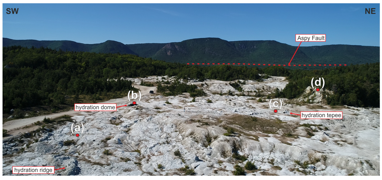
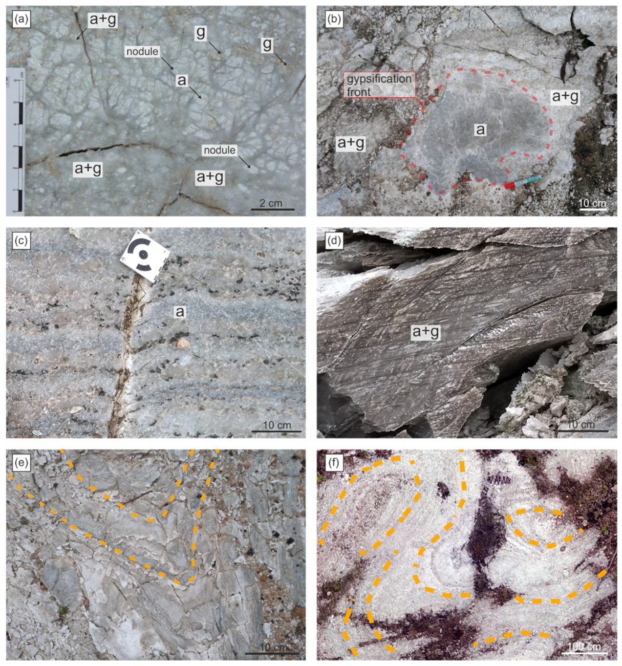
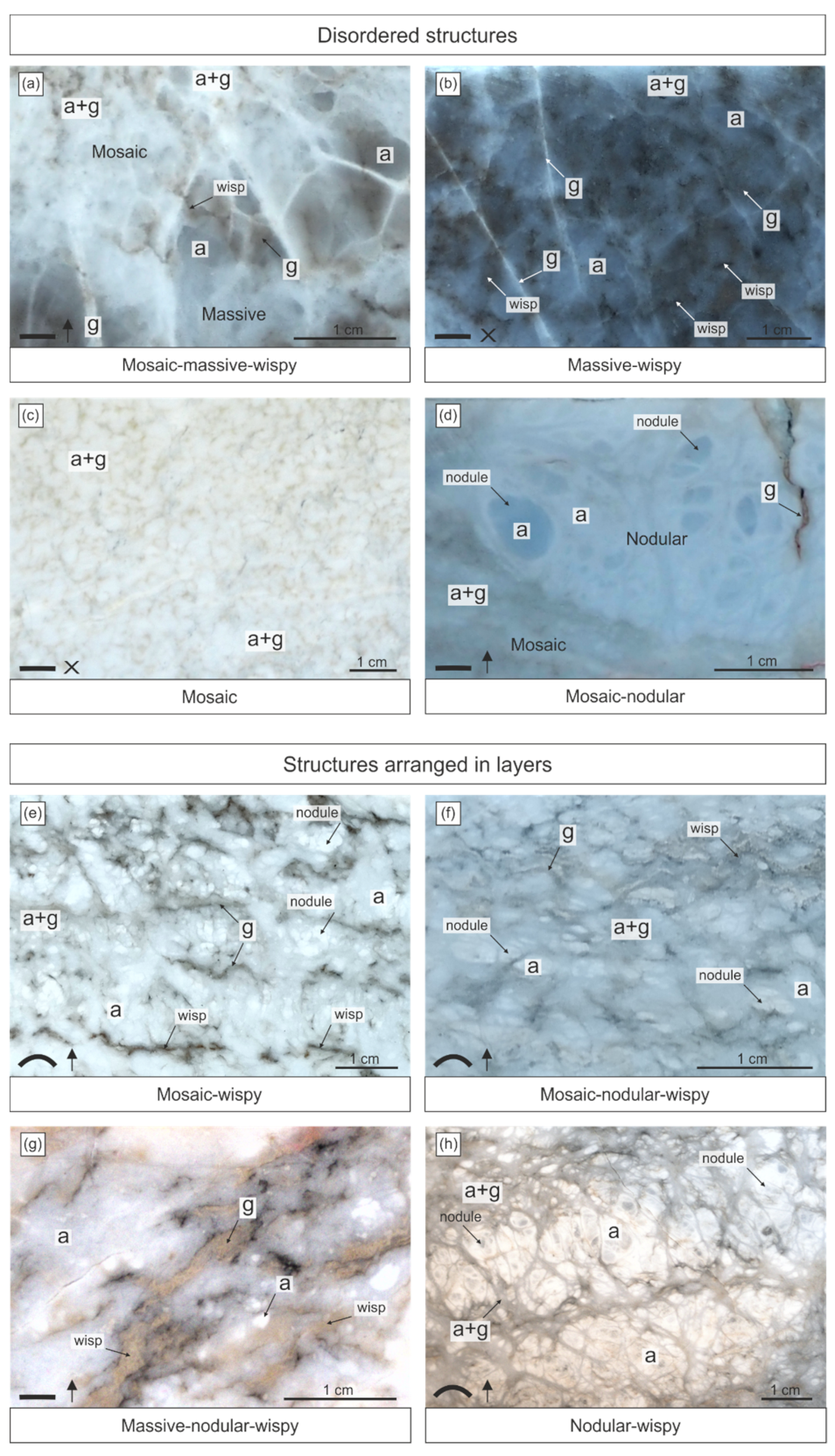
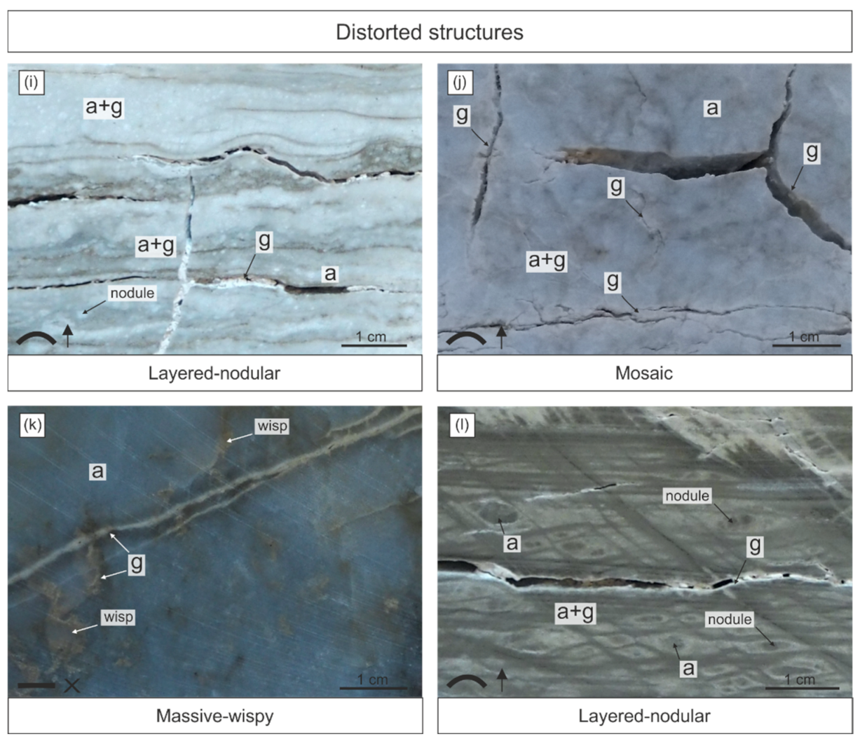
The studied weathering zone is bimineral in composition involving anhydrite and gypsum present throughout the site. The other minerals occur sporadically as accessory components constituting less than 2% of the rock mass. We did not find limestone beds intercalating gypsum and anhydrite, locally occurring dolomite crystals, ulexite veins infilling joints, and the beds of calcite nodules (1–6 cm in size) containing crystals of howlite inside (a mineral first discovered in Nova Scotia [74]), documented in the northern part of the site by Goodman [75]. The presence of gypsum and anhydrite was confirmed in the optical and scanning electron microscope (SEM), and also by EDS analysis, ICP-EOS/ICP-MS spectrometry, Raman spectrometry, and XRD. The majority of the gypsum-anhydrite rocks at the bottom of the quarry contained 40–80% gypsum (66% of the 112 samples analysed by hydrostatic and helium pycnometry methods). Only 4% of the samples represented nearly pure anhydrite (0–10% of gypsum) and 6% of the samples were nearly pure gypsum (90–100% of gypsum). Calcite, quartz and celestite were recognized by SEM, ICP-EOS/ICP-MS spectrometry, ICP-EOS/ICP-MS and XRD. Celestine (SrSO4) was found within both anhydrite and gypsum as randomly scattered irregular aggregates and single crystals (50 to 300 µm in size), predominantly anhedral in habit.
According to observations made 70 years ago by Goodman [75] (p. 13) anhydrite beds at Dingwall formed “a gentle dome which slopes off in all directions with dips of 5°–10°”. Recent observations indicate that the gypsum-anhydrite beds in the quarry show a variable strike, both straight and also curved and wavy. Layers are seen on the bottom of the quarry as more or less complicated folds (Figure 4e,f). The angle between the two fold limbs is often obtuse but also sharp (Figure 4e,f). In the plan view, in a horizontal intersection, the strike is most commonly directed NS or NE-SW and the dip is low, less than 30°, only in some exceptional places it attains 60° (Figure 2). In many places, layers are horizontal or nearly horizontal. The direction of layering is commonly disturbed by deformations induced by expansive hydration.
The rocks in the quarry are intensively fractured. The most prominent is a system of master joints composed of two and three sets (Figure 1e). The orientation of joints is approximately vertical. They are documented both in the rock walls that are several meters high and in the bottom of the quarry where deformations forming as a result of anhydrite hydration are common. Dense networks of other fractures occur in the studied site, most of them related to physical weathering. A prominent part of the fractures is connected with the deformations generated during volume increase of the weathering rocks. These fractures have formed and opened in the surface layer of the rock in places of occurrence of hydration domes, tepees, and ridges [21,34,35]. There are also fractures produced by quarry operations.
Anhydrite and gypsum exposed in the quarry are subjected to both physical and chemical weathering (Figure 1c). Physical weathering causes the fracturing and disintegration of the rocks into smaller blocks or pieces, accelerating their chemical transformation–karst dissolution and anhydrite hydration.
The chemical weathering of anhydrite involves its hydration, which has an expansive character. It generates the mentioned spectacular deformations at the bottom of the quarry. The process has been taking place under the influence of atmospheric (meteoric) waters [21,29]. These waters come into contact with the anhydrite at the surface and in the subsurface, particularly below the groundwater table (i.e., in the vadose and the phreatic zone). The anhydrite massif is prone to karstification and interconnected karst fissures present in this massif [52] certainly result in that the groundwater table being rather deep below the surface; however, surely not deeper than the sea level. Only in the lowest eastern part of the quarry is the water table is close to the surface (see cross-section in Figure 2). The water table within gypsum-anhydrite massif was 2–7 m below the surface in the boreholes situated 500–700 m from the quarry, at an altitude of 15–58 m a.s.l. [76].
Expansive hydration (expansive gypsification) is recorded within three fields: the western, the central, and the eastern field, on a total area of approx. 78 ha, extending 1850 × 1400 m (Figure 2). Fields are situated from 2.5 to 44.0 m a.s.l. A few ponds, up to several dozen meters in size, occur in local depressions several meters above the sea surface. Their location is probably determined by the groundwater table that falls towards the Atlantic Ocean. The small part of the weathering zone in the eastern field, located right next to vast wetlands, occupies the lowest terrain ordinates (2.5 to 7.0 m a.s.l.).
Based on macro- and microscopic observations the area of the weathering anhydrites can be roughly divided according to the degree of advance of gypsification into three zones: (1) initial gypsification (up to 20% of gypsum in the rock); (2) advanced gypsification (from 20% to 80% of gypsum in the rock); (3) mature gypsification (more than 80% of gypsum in the rock; Figure 3).
Initial gypsification is noticed sporadically in the sites of occurrence of almost unchanged anhydrite, where deformations and fractures related to the volume increase are not observed. These parts of the rock are almost entirely built by anhydrite with only a small amount of gypsum in and around the fissures.
The advanced gypsification zone is characterized by a variable gypsum/anhydrite content ratio that is characteristic for almost the entire quarry bottom, where numerous deformations, such as fractures, domes, and ridges, commonly occur, but also where the surfaces of the rock remain undeformed.
Mature gypsification zones are found in places exposed to the greatest impact of water, i.e., in the lower parts of elevated rock layers or blocks and in fractures or other places, like depressions and concavities of the quarry bottom, which collect water of meteoric derivation. Mature gypsification zones commonly contain fractures, open or filled with gypsum cement.
Nearly completely gypsified anhydrite rocks with an almost 100% gypsum content cover also the quarry walls, rising several meters above the quarry bottom, representing unexplored parts of the gypsum deposit. The greater degree of gypsification observed in the walls high over the bottom of the quarry is related to the hydration that started earlier, before the quarry mining operation. It can be presumed that, before 1933, the zone of hydration (gypsification) extended to a depth of more than 15 m in the studied area, like in the environs of gypsum quarries at Sugar Camp and Melford in the south part of Cape Breton [77]. Nearby the studied site, at Cape North (a town next to Dingwall), the gypsum deposits (gypsified anhydrite) covering the anhydrite bedrocks are 7.62 m thick [78]. The beginning of gypsification at Dingwall may extend back in time to creation of the characteristic schlottenkarren karst relief [79] that is present in the studied site. According to data from the Avon Peninsula of Nova Scotia similar karst relief was created already before the Last Glacial Maximum (before the Wisconsinan glaciation) or during postglacial times [52]. Water penetrating the upper part of the rock not only creates the karst surface but also percolates deeper and reaches the anhydrite rock, beginning the gypsification processes. In the Dingwall quarry area, numerous schlottenkarren forms of karst relief (i.e., dense network of funnel-shaped sinkholes draining into vertical cylindrical shafts) [52,79] were observed (Figure 1f and Figure 3d). Such more than 20 m deep narrow sinkholes were documented in the gypsum and gypsum-anhydrite rocks by Goodman [75], who noticed that “when a sink hole reaches anhydrite it goes no deeper” [75] (p. 50). In places, remnants of sinkholes up to 1 m deep are observed at the bottom of the quarry [35]. Locally, the bottom is covered by weathering debris, initial soil, and poor low vegetation which mask the image of rock structures. Artificial debris produced during mining and other quarry operations mainly occurs along the walls of the quarry and roads passing the site.

6. Structures

Structures of the rocks were described on the basis of macroscopic observations paying attention to different anhydrite and gypsum content. The presence of calcite was tested by diluted HCl acid. Anhydrite and gypsum were identified in the field by their well-known features (hardness, cleavage) with particular emphasis on the density measured by the hydrostatic method. Density measurements helped to identify the parts of rocks composed of gypsum, the parts composed of anhydrite, and the parts being a mixture of gypsum and anhydrite. However, in the field, the spatial distribution of these two minerals within very fine-grained rocks was difficult or impossible to determine, since both minerals look very similar. Structures were observed also on the cut surfaces of the rocks in the laboratory, where the distribution of minerals was easier to recognize with the help of microscopic observations.
Structures [55] were distinguished mainly on the basis of visual observations of the rock surfaces, taking into account their slight colour differentiation, resulting from a mineral composition, sizes of grains, porosity and other features.
Our observations confirm that, although it is impossible to distinguish with certainty gypsum from anhydrite in fine-grained rock only based on colour, the colour of the rock can give important information or suggestions concerning the distribution of the discussed minerals in gypsum-anhydrite rocks [9,80], and the presence of foreign admixtures. It is relatively easy to identify gypsum on the surface of fine-grained gypsum-anhydrite rocks when the gypsum forms massive and coarse-grained aggregates of crystals devoid of inclusions. The larger the crystals, the more visible such aggregates are. These places are remarkably darker than the surrounding rock composed of a very fine crystalline anhydrite and/or gypsum. Additionally, they can show lower hardness (2 in Mohs scale). The darker colour of gypsum results from the perfect transparency of large gypsum crystals [31,32,81,82]. In other cases, the determination of mineralogical composition based only on colour can be misleading. Contrary to the case described above, fine-grained gypsum can be remarkably whiter than the adjoining anhydrite, as has been documented by many authors (Figure 2 in [7]) (Figure 6A,B in [8]) (Figure 1A in [17]) (Figure 9 in [26]) (Figure 32 in [57] (p. 594)) (Figures 34a and 38 in [83]) (Figure 2 in [84]) ([85], pl. 1A) (Figure 4 in [86]). Porous fine-crystalline masses of gypsum crystals (with tiny intercrystalline pores) are usually whiter than the massive aggregates of the same crystals (e.g., [82]). The same is true for the fine-crystalline anhydrite (authors’ observations). Anhydrite can be present as a greyish, slightly translucent variety, as well as the milky, less translucent one. The homogeneous mixture of both minerals can show various colours being indistinguishable from pure gypsum or pure anhydrite varieties of these rocks. Nevertheless, colour differences suggest the presence of some mineralogical and structural differences, which require analytical studies.
Most generally, the observations permitted the recognition of four main structures: nodular, mosaic, massive, and layered (Figure 1d, Figure 3, Figure 4 and Figure 5), similar to these characterizing anhydrite rocks [56]. Open fractures are generally omitted in distinguishing these structures. Gradational transitions between all these structures are commonly noted. Additionally, many rocks are characterized by the presence of thin irregular wavy streaks with sharp ends or rows of patches of apparently different (usually darker like brownish, greyish) colours than the rock mass around them. These streaks commonly split and run along the margins of some nodules but do not form closed mesh nets as in the well-known chicken-wire structure [56]. We called these wisps, similarly to Holliday [87,88] and Shawkat [59], although they used this word for the description of the streaks of foreign non-evaporitic sediment within calcium sulphate rocks. According to Holliday [87] (p. 37), nodular and mosaic (chicken-wire) structure grades into a wispy structure that is defined by him as this “in which individual nodules are still more or less recognizable but the matrix no longer forms a continuous mesh and occurs only as thin discontinuous wisps”. The studied wisps are mostly composed of gypsum or gypsum and anhydrite.
The nodular structure is characterized by more or less homogeneous nodules (commonly 0.5–1.0 cm in size; or meganodules if ≥0.5 m; see [89]) which are round, oval, and irregularly elongated, and surrounded by masses of rocks of different structures, commonly of the mosaic structure (Figure 5d–f). Nodules occur separately. The smaller nodules merge into larger ones with a homogenized internal structure (Figure 4a and Figure 5h). The nodules never show the sharp cauliflower shaped margins that are typical of displacive anhydrite nodules (e.g., [90]), but are seen as patches with obliterated boundaries defined rather by the surrounding matrix. The nodules have a dark core surrounded by a lighter envelope or a white core with a darker envelope. Some nodules, also obliterated and indistinct nodules present in the mosaic structure, show a dark interior surrounded by a whiter envelope passing again into a darker zone in the most external part (Figure 4 and Figure 5d–h). These nodules appear to be composed of an anhydrite (or mainly of anhydrite) core surrounded by gypsum-anhydrite and a gypsum matrix. This type of anhydrite nodule seems to be of the secondary weathering origin connected with the way of hydration and represent parts of the anhydrite rocks more resistant to gypsification. Similar forms were called secondary anhydrite nodules by Shawkat [59] and Hunt et al. [26] described such forms as corestones of anhydrite.
The mosaic structure is composed of merged coalesced “nodules” however without sharp clear boundaries between them, as well as without a sharp external boundary. The cores of the nodules are commonly white or light in colour but in some places, they are light grey. They are generally more resistant to weathering and are surrounded by narrow streaks or wider masses of gypsum and gypsum-anhydrite mosaic rock which is clearly darker in colour (Figure 4a). Coalesced masses of nodules can be chaotically arranged or arranged in layers (Figure 5f).
The massive structure is seen as a more or less homogeneous surface without any distinguishable nodules or nodule-like forms, both separate ones or coalescing into mosaic (Figure 5a,k). However, the rock surface can be spotted in a more or less irregular manner.
The layered structure is easy to recognize by the presence of even, intercalating, light and grey bands representing layering (Figure 5e,g). They continue for many tens of meters in the quarry and clearly represent the primary bedding obliterated by diagenetic and weathering processes. Small-scale contorted bedding was recorded from Dingwall by Goodman [75]. Bands or layers show an internal relatively homogeneous (massive) or slightly nodular or mosaic structure (Figure 5f,h). The layered structure can be considered as a specific separate type of structure in which rather homogeneous layers (which define this structure) can show an overprint of the nodular or mosaic structure.
Previously described wisps can be present in each of the listed structures. In combination with these structures, they create the mosaic-wispy, the nodular-wispy, and the massive-wispy structures (Figure 5). There are also more complex combinations of these structures, such as, for example, the mosaic-nodular-wispy structure (Figure 5f). The layered structure wisps, as a rule, are concentrated along the surfaces of the layering. Gypsum wisps occur both in hydrated gypsum-anhydrite rock (Figure 5b,c,e,f,h), but are also randomly scattered in the interior of unhydrated anhydrite rocks.
All of the above mentioned structures and combinations of them appear in a mixed form and can be additionally subdivided into three groups of structures: the disordered structures (Figure 5a–d), the ordered structures in which parts of the rocks creating the structures are arranged in more or less visible layers (Figure 5e–h) and the structures disturbed by fractures (Figure 5i–l). The presence of fractures, empty ones, filled or partly filled with gypsum cement, is a characteristic feature of the latter structures (group of disturbed structures).
Gypsum-anhydrite and anhydrite rocks have been and still are the subject of ongoing physical weathering and hydration, which results in the formation of fractures (Figure 4b,d and Figure 5i–k). Fractures are commonly parallel or perpendicular to the detached surface rock layer (Figure 5i,j,l), but also are arranged irregularly (Figure 5j). The majority of these fractures seem to be related to the volume increase accompanying anhydrite hydration or to the physical weathering. The mentioned larger scale systematic joints (master joints) of tectonic origin running at a distance of many meters are also observed.
Macroscopic observations reveal that larger (>0.5 m) masses of anhydrite bedrocks, not subjected or partly subjected to gypsification, are found only in the form of spherical zones, irregular elongated nodules extending to several meters in length, and also as even beds (Figure 4b,c). Anhydrite in these places is characterized by a massive or massive-wispy structure, in places distorted by fissures and fractures that are empty or filled with white gypsum (Figure 3a and Figure 5b,k). The zone that separates this anhydrite from the anhydrite-gypsum and gypsum rocks is often clearly visible and marked by white and slightly grey colours that are different from the grey colour of anhydrite. The zone between anhydrite and gypsum-anhydrite rock is a gypsification front in the macroscopic sense (Figure 4b). A characteristic feature behind the gypsification front is the presence of a network of gypsum or gypsum-anhydrite bands or streaks increasing in number and thickening in direction outside the anhydrite zone as it is best seen in Figure 4a and Figure 5h. Such a feature is characteristic for the weathering and hydration zones of anhydrite in many regions of the world [5,8,26,31,32,38,39,91,92,93,94,95].
The other characteristic forms are separate masses of anhydrite-gypsum rocks occurring between vertical joints or fractures and showing features of spheroidal weathering (Figure 1d and Figure 3a). Corestone of anhydrite rock is surrounded by exfoliated gypsum-anhydrite crusts or shells. Similar forms, however evidently three-dimensional in shape, are known as anhydrite “cannonballs” from the outcrops of the Carboniferous Windsor Group evaporites in nearby Canadian New Brunswick Province [39]. They are developed in places where the anhydrite massif is cut by intersecting joints or fracture systems. These fractures are the way of water infiltration or flow and the cause of centripetal hydration of anhydrite blocks [5]. According to Webb [39,96] the spheroidal structures occur at the major gypsum-anhydrite hydration front close to the bottom of the anhydrite weathering zone. At Dingwall they are noted at several places at the bottom and walls of the quarry.
In several places in the site, rare peculiar flat layered or laminated deposits built of gypsum and anhydrite were identified (Figure 4d; layered, nodular structure in Figure 5l). Parallel lamination in this rock is cut by oblique parallel strips of gypsum, and anhydrite nodules appear at the intersection of the laminae and the strips. The nodules are elongated (flattened) parallel to the lamination. Some nodules are composed of a mosaic of several flatted nodules resembling rhombs or lenses in shape. Similar structures formed by “flowage” and gypsification along rhomboidal pattern of fractures in anhydrite cap rocks were described by Goldman [9].
The structures described above are common in the anhydrite-gypsum deposits which passed the burial-exhumation cycle and underwent two drastic mineralogical transformations during which the primary gypsum deposits were dehydrated and replaced by anhydrite in the diagenetic environment and later the originated anhydrites were hydrated and replaced by gypsum in the weathering zone (e.g., [59,86,87,88]). The structures recorded at Dingwall are interpreted as the result of such diagenetic and weathering transformations (dehydration and rehydration) which nearly entirely obliterated the primary features of the presumed original gypsum protolith (except of its layering).

7. Anhydrite and Gypsum Fabrics
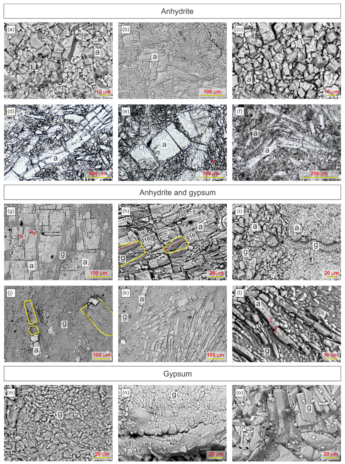
Samples showing deformations related to volume expansion were the main object of fabric analysis. Samples with both only anhydrite composition, gypsum-anhydrite composition, and composed only of gypsum were analysed separately. They showed differentiated fabric clearly related to advance of gypsification in the weathering zone.

7.1. Anhydrite

Anhydrite representing the ungypsified bedrock occurs as accumulations of euhedral and occasionally subhedral elongated crystals, ranging in size from 5 to 500 µm, similarly to many other ancient anhydrite deposits (e.g., [57,90,97]). The crystals are most often lath-like, and are rarely barrel-shaped with convex side faces. They form massive, almost non-porous fabric; slightly higher porosity appears in places close to larger open pore spaces, like fractures. The fabric is inequigranular, and the crystals are roughly divided into two groups in terms of sizes, the crystals with a length of 5–50 µm (Figure 6a–c) usually constituting 60–80% of the rock and the crystals 50–500 µm long irregularly arranged within the samples (Figure 6b,d–f).
The crystals form disordered and ordered fabric. In disordered fabric, they show variable sizes and different orientations with respect to each other. Most commonly, the lath-shaped crystals are arranged in an orderly fashion with an elongation parallel to each other, touching each other with flat side faces, which is known as face-to-face orientation [90]. Crystal boundaries are often straight and even, and are rarely serrated. A pile of brick fabric [98,99] is observed in some places. The anhydrite laths show also decussate fabric typical of many anhydrite deposits (Figure 6e) [60,90,97]. Sub-parallel elongated crystals arranged in a wavy manner, as in the felted-aligned fabric [56,83,97], are equally frequent. Locally anhydrite laths are arranged radially (similarly as in fabric documented by Aleali et al. [100] (Figure 6k in this paper).
In general, a typical feature of the anhydrite before gypsification is compact fabric without visible porosity (Figure 6a). The most densely packed crystals are found within the anhydrite nodules and meganodules which apparently were not subjected to weathering and disintegration due to their massive fabric blocking the access of water. Porosity outside nodules appears in the form of gaps or irregular small voids between the crystals (Figure 6c) and as fractures and tiny fissures running along the cleavage within the crystals (Figure 6h).
Anhydrite not subjected to gypsification is also characterized by some deformations, like breaking, displacement and rotation of the crystals. Larger crystals are fractured along the cleavage planes and show narrow intracrystalline pores within the fractures. Fractured crystals formed structures resembling brushes (similar to those recorded at Pisky) [31], where the crystals are split off on one side (Figure 6d–f). The crystals are often fragmented transversely to their elongation and crystal fragments are displaced forming folds or forms resembling tepee structures (Figure 6f), also known from Pisky [31]. Zones of crumbling, composed of fine crystal fragments, are present as well (Figure 6d,f).
Similar deformations and fractures are relatively common in anhydrite deposits [31,97]. Their origin is presumably related to mechanical breakage caused by compaction during the reduction of bed thickness which accompanied the transformation of the primary gypsum into anhydrite [2,28,31,101].

7.2. Anhydrite and Gypsum

Samples containing anhydrite and gypsum show many features typical of the zones of anhydrite gypsification, such as inter-grain and intra-grain mesh fabric (e.g., [31,102]). Gypsum occurs within anhydrite in the form of thin veins or a network of veins running along grain boundaries (in the inter-grain mesh fabric; e.g., Figure 6g,h) and across anhydrite grains along their cleavage planes (in the intra-grain mesh fabric; e.g., Figure 6k). Monomineral composition, the shape of some veins having sharp external boundaries which fit themselves, and their relatively constant thickness suggest that such veins represent fractures filled with gypsum [103].
The larger anhydrite crystals “cut” by networks of gypsum “veins” running parallel and subparallel to anhydrite cleavage planes in the intra-grain mesh fabric provide the best insight into the formation mechanism of gypsum in this fabric. Coarse-grained anhydrite crystals are fragmented and their pieces are separated mainly along the three directions of anhydrite cleavage: the perfect, the very good, and the good cleavage. Because the cleavage planes intersect at right angles, the anhydrite fragments are commonly cuboids which are usually seen as rectangles on the surface of a thin section plate. The spaces between the more or less separated rectangular anhydrite fragments are occupied by fine-grained secondary gypsum. In many cases, these fragments perfectly fit each other, like jigsaw puzzle pieces, and can be collected together to form the original anhydrite crystal (Figure 7). This gives the impression that the anhydrite fragments moved apart and now the anhydrite occupies more space than before. Anhydrite fragments surrounded by gypsum are observed both in a parallel position and slightly displaced, with rotations by a few to several dozen degrees and relocations by even more than several µm. Some adjacent separated anhydrite fragments are sometimes connected by more or less displaced and rotated thin cleavage fragments of anhydrite that remain attached or nearly attached to both crystals, forming a kind of bridge between them (Figure 7). By analogy to similar structures in mineral veins formed by fragments of the wall rocks included in the vein (Figure 4 in [104]), it can be proved that the gypsum in the space between the anhydrite fragments was not formed by replacement of the anhydrite [104] (p. 66) but occurs in free space created by the separation of anhydrite fragments [31] (p. 293). The cleaved fragments of anhydrite were separated from the parent anhydrite crystal by the continued growth of gypsum [104] (p. 65). This gypsum supposedly represents displacive growth or, partly free growth as cement (like in the example illustrated by Mossop (Figure 76 in [105]). The occurrence within the zone of expansive hydration of anhydrite strongly supports the view that it was displacive growth. Displacive growth of gypsum in one, two or three perpendicular directions is thus the direct reason for the volume increase.
In many other cases, the anhydrite fragments dispersed within the large volume of gypsum are small, subhedral and anhedral. Their boundaries do not fit each other because they were partly “consumed”, replaced by gypsum. Lack of such fit can be treated as evidence of replacement [66,104] (p. 134). Also, the fragments of anhydrite showing good fit present evidence of replacement. The originally sharp edges of rectangular cleavage fragments are rounded due to replacement of the corner zone by gypsum (see “replacement effect” in Figure 7, and ([31], Figure 5e,f). In places, gypsum replacing and/or displacing anhydrite along its cleavage planes show traces of the perfect 010 cleavage parallel to orientation of the traces of the cleavage planes of the anhydrite (Figure 6h). Such relations indicate that the gypsum crystallized forming the epitaxial intergrowth with anhydrite [31,91]. Locally, the anhydrite is replaced by gypsum in a pseudomorphic manner (Figure 6h,j) without changing the original crystal shape outline [106]. The course of pseudomorphic replacement of anhydrite by gypsum is well visible when a grain of anhydrite is replaced only partly by gypsum (Figure 6h,j). All of these observations indicate that gypsum replaces anhydrite and also grows, displacing the anhydrite fragments and/or crystallizes as cement in open spaces between them.
Towards the zones entirely composed of gypsum, the number of anhydrite decreases. Gypsum crystals surround the untransformed relics of anhydrite crystals. Such anhydrite can occur in the form of small anhedral crystals with a size of up to several µm, but also as larger crystalline aggregates or individual crystals with sizes above 100 µm. In the more gypsified zones, gypsum crystals up to 100 µm in size occur within a matrix composed of smaller gypsum crystals 5–20 µm and some dispersed anhydrite.
Porphyrotopes of secondary gypsum surrounded by massive impermeable anhydrite were not observed.

7.3. Gypsum

The gypsum formed by gypsification of anhydrite is predominantly fine-grained and composed of anhedral crystals, ranging from a few to 30 µm in size. Such sizes are typical of the alabastrine secondary gypsum, being the product of gypsification of anhydrite (<100 µm) [89]. The crystals form xenotopic fabric (Figure 6m,n) [63] that is characteristic of the secondary alabaster [14]. The secondary gypsum crystals are generally smaller than the crystals of the parent anhydrites. Within this type of gypsum, fractures and pores up to several dozen µm are observed partly infilled with coarse-grained gypsum cement (Figure 6o). This gypsum is the most common in the studied rocks.
The less common type of gypsum is coarse-grained with crystals, from a few to about 20–300 µm in size also showing xenotopic fabric (Figure 6m,j). Gypsum pseudomorphoses after anhydrite are recorded in this type of gypsum.
Most easily recognizable gypsum cement infills the fractures, and the fractures in the detached and upraised layers are opened due to expansive hydration of anhydrite (Figure 6o). Crystals in the fractures and voids are oriented with elongation perpendicular and subperpendicular to their walls in the manner typical of cements [62], but also showing irregular orientation, infilling the entire free space or creating bridges connecting the opposite walls. These crystals are usually larger compared to the other gypsum crystals. Their length ranges from several to 300 µm and, in places, up to 1000 µm. Crystals occupying central parts of the infilled pore spaces are the largest, which is a feature typical of cements [62]. They show subhedral to euhedral, and rarely anhedral, habits, and form idiotiopic, hypidiotopic, and, less commonly, xenotopic fabric. Both small and large intercrystalline pores are common within such gypsum cements. In horizontal fractures, crystals of gypsum cement occur mainly attached to the lower walls of the fracture. The upper walls are free or only in places covered with a smaller amount of gypsum cement.

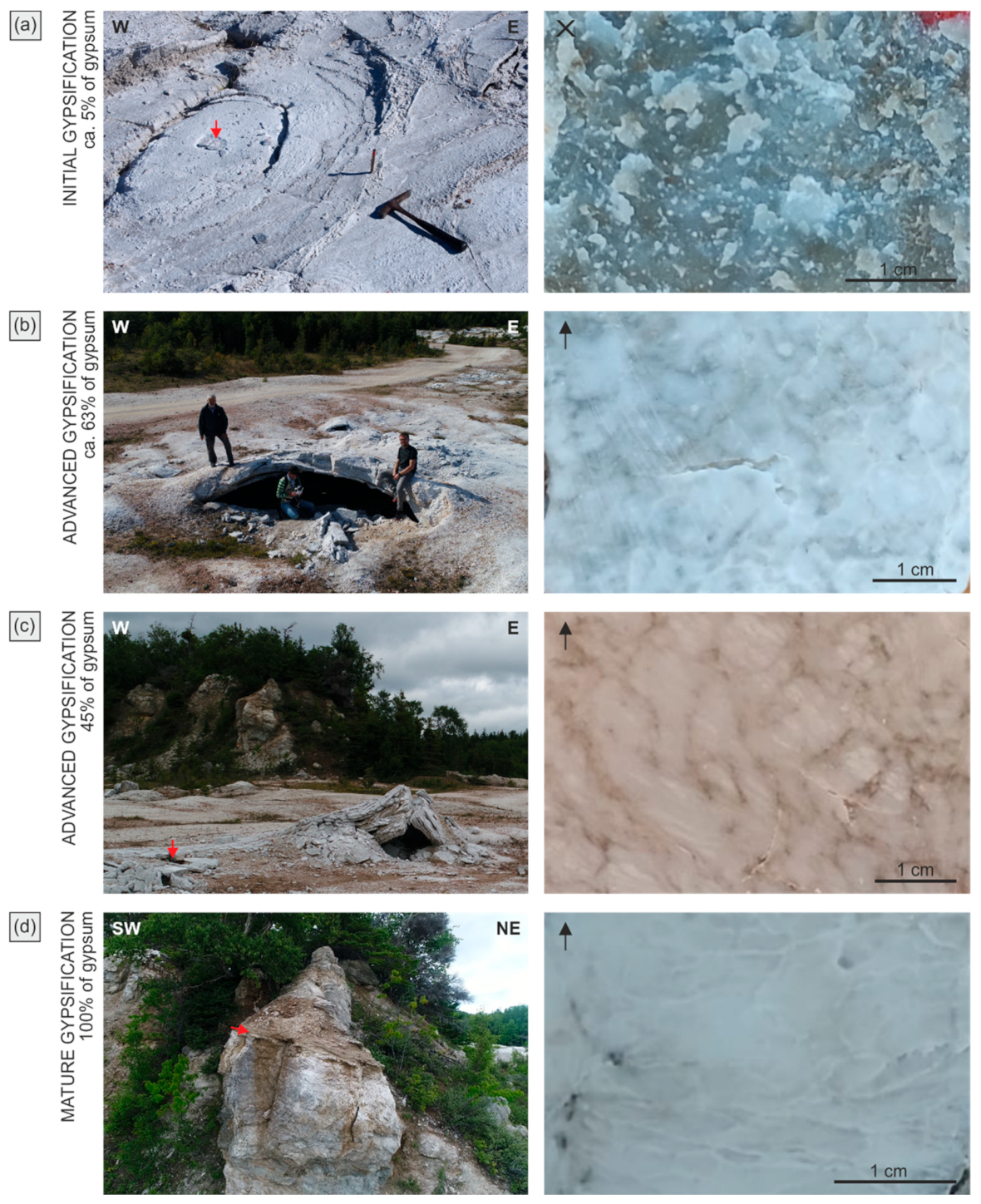
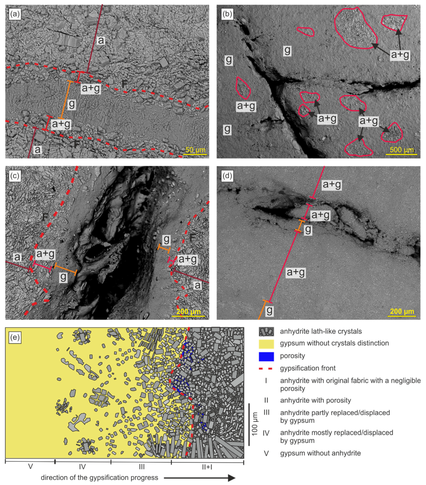
8. Gypsification Zone

The surface of anhydrite and gypsum rocks in the quarry is undergoing intensive karst dissolution due to direct and frequent contact with running water of the atmospheric derivation. This has led to the development of spectacular gypsum and anhydrite karren [33,36]. According to our observations, dissolution processes dominate on the exposed surfaces of the rocks and gypsification of anhydrite does not occur directly on such surfaces, which was already noted by Goodman [75]. Schlottenkarren and open large fractures with exposed walls, like some vertical joints, are not able to store water necessary for hydration of anhydrite. They are good conduits that transport the water deep down in the weathering zone. The water can escape from the surface zone before reaching saturation or supersaturation with respect to the gypsum necessary for gypsification [107,108]. The surfaces of such fractures and joints are thus not the best sites for gypsification.
Gypsification develops within the anhydrite bedrock mainly in places favourable to the influx or infiltration of water, and to storing it for some time, such as small semi-closed fractures or networks of intercrystalline pores. It seems that very thin fractures or narrow lower ends of some larger fractures or pore voids are especially favourable for gypsification because of their ability to collect and store the water needed for the hydration reaction. This water can infiltrate from such places into a surrounding more massive anhydrite rock, promoting the gypsification processes. Therefore, as a rule, around thin fractures and nets of intercrystalline pores, the gypsification zone develops (in the microscopic sense) with a very characteristic structure described below. More advanced or complete gypsification is observed in the interior of such places whereas outside of them the effects of gypsification gradually disappear. These places can be both the starting point for anhydrite hydration and also the endpoint when they are sealed with newly crystallizing gypsum in the process called “self-sealing” [107,109,110,111,112,113]. It seems that the crucial process for the further advance of gypsification is the creation of the new places with suitable porosity (narrow fractures or intercrystalline pores) within anhydrite and gypsum-anhydrite rocks.
Fractures are a key factor in the migration of aqueous fluids. Actively forming and opening fractures in the anhydrite bedrock are thus most important for the start and advance of gypsification. They can be produced by physical weathering and also by stress in the rocks related to expansive hydration. Some fractures in the anhydrite bedrock do not show the influence of gypsification and appear to be formed directly by recent weathering. Their spatial distribution is most often vertical and horizontal, but also oblique. Some of them have an opening of a few µm wide and are potentially good places for the start of gypsification. The atmospheric water slowly migrates through such fractures, which is a necessary condition for initiating gypsification of the anhydrite [107,108]. Because, as a result of gypsification, the volume of anhydrite-gypsum rock increases, such fractures can become much wider than observed before gypsification. Crystallizing gypsum can also partly or entirely seal them. The ongoing expansive hydration can generate new fractures which can evolve in the same way. Gypsification zones develop around such fractures.
The characteristic microscale zones related to the advancement or direction of gypsification are very similar to the other gypsification zones; for example, those described from the Triassic anhydrites in Switzerland undergoing expansive gypsification in tunnels [95], or those recorded at Pisky [31].
The gypsification zones comprised of gypsum and/or anhydrite are characterized by the order of occurrence of both minerals, depending on the degree of transformation and the resulting spatial relations of both minerals (Figure 8). Going from the area without any effects of gypsification, the following parts of the gypsification zone can be distinguished: (1) anhydrite with unchanged fabric, generally without porosity except fractures; (2) anhydrite with microporosity, particularly around some fractures; (3) anhydrite partially replaced by gypsum, mostly along the grain boundaries (in this part the volume of anhydrite is larger than the gypsum volume); (4) anhydrite replaced by gypsum with anhydrite relics in the form of single crystals and islets of crystals scattered within gypsum (the volume of anhydrite is here smaller than the volume of gypsum); (5) exclusively gypsum, without anhydrite.
The described sequence of changes in the transition zone from anhydrite to gypsum is commonly gradual and extends in space to a length of several millimetres or centimetres. However, often, the sequence is shortened and one part (or more than one part) of it is omitted, e.g., the microporous anhydrite. For example, it is commonly observed that the gypsum part of the rock contacts with the anhydrite part almost directly only with a narrow strip of interlocking minerals several µm in thickness along with the contact (Figure 8a). This situation occurs most often in the case of single gypsum veins penetrating the massive anhydrite in places where this rock was previously fractured. In other cases, the typical sequence of mineral occurrence is observed. The narrow boundary between the gypsum and anhydrite part of the rock described above (Figure 8a) shows very well the range of influence of the water fluids on the transition of anhydrite into gypsum and represents the gypsification front in the microscale (Figure 8a,c) [31]. The gypsification front is defined here as the first occurrence of secondary gypsum among the anhydrite rock [95].
As gypsification progresses, the zone occupied exclusively by the gypsum widens. It is especially well seen around some fractures evolving into gypsum veins. The walls of such fractures are composed of gypsum. Their central part is commonly opened and a certain amount of gypsum is crystallized there in the form of cement. Such veins penetrating the anhydrite rocks are similar to the so-called replacive gypsum veins described by Shearman et al. [114], who suggested that term to distinguish such veins from the veins formed exclusively by replacement—the replacement veins.
The replacive veins occur only within anhydrite and show dual origin; the external part of them is created by the replacement of anhydrite by gypsum and the internal part is a fracture filling formed by cementation [114]. The studied veins differ from the replacive veins because the external parts of the former ones can show evidence of both replacive and displacive gypsum growth, as proved above. Therefore, they show also, at least locally, a character of displacive veins [5]. Such a type of veins is typical of the zones of expansively weathering anhydrite [31]. Hilgers and Urai [115] proved that in the syntectonic growing fibrous veins of gypsum the “crystallization force” of that mineral can participate in the driving forces opening such veins. According to them the opening of the fibrous gypsum veins by “force of crystallization” cannot be excluded, as previously suggested by Taber [104] (see, [116,117], for a discussion of his theory).

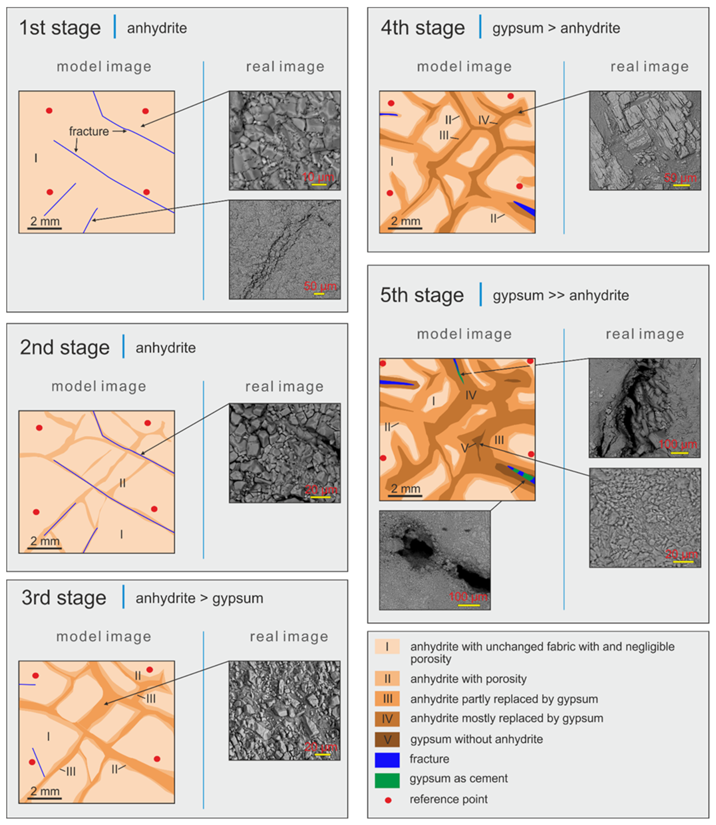
9. Model of Anhydrite Gypsification

Based on macro- and microscopic observations and literature data, the gypsification model of anhydrite rock with a negligible porosity value is proposed, consisting of five stages (Figure 8e and Figure 9). The hydrogeological conditions are assumed in accordance with those prevailing at Dingwall, and are characterized by good variable availability of rainfall and snowfall. Fresh water soaks into the rock during rain and snow melting. The water table is below the zone of gypsification. The gypsification is gradual and irreversible and the duration of the stages is variable.
In the first initial stage (the fracturing stage), the anhydrite is massive and dense without significant intercrystalline porosity. It is assumed that occasional fractures intersecting this anhydrite appear as a result of physical weathering, stress induced by expansive hydration of anhydrite in the vicinity, or other factors (first stage in Figure 9). Opening of the fractures allows free access of water to the rock interior.
In the next stage (the dissolution stage), fresh water begins to dissolve anhydrite crystals in the most accessible places, slightly widening the fractures and fissures. The crystallization of gypsum does not yet start because supersaturation of solution with respect to gypsum is not achieved (second stage in Figure 9) [107,112]. A network of narrow intercrystalline pores running along the crystal boundaries develops locally in the anhydrite surrounding the fractures and spreads into the massive anhydrite rock. Larger crystals break and dissolve along the cleavage surfaces. In this stage, a mosaic of two types of anhydrite is formed; the massive anhydrite and the anhydrite with greater porosity which includes fracture and intercrystalline porosity (Figure 9) [118]. The porous anhydrite forms a network penetrating the massive anhydrite. The causes of appearance of the intercrystalline porosity in the anhydrite (documented at Dingwall within gypsum-anhydrite rock with nodular structures directly nearby and around the massive anhydrite nodules; Figure 6c and Figure 8e) remain enigmatic. The similar inter- and intracrystalline porosity “opened for gypsification” and occurring just in front of gypsification zones was recorded in the anhydrite cap rocks by Goldman ([9], p. 28, pl. 62, Figure 1). He attributed the origin of this porosity to tectonic forces acting in the cap rocks. The similar intercrystalline (grain boundary) and intracrystalline (cleavage) porosity is easily produced in gypsum rocks subjected to deformation [119]. In the case of Dingwall the intercrystalline porosity can be the product of weathering facilitated by the presence of fractures in the vicinity. Auvray et al. [120] described the increased porosity produced by dissolution by vapor and/or liquid water within the 1.5 thick weathering zone developed on gypsum pillars in underground mines.
In the third stage (Figure 9), the water fluids continue to penetrate and dissolve the anhydrite along with the previously initiated pore spaces increasing the permeability of these zones. The permeability increase by dissolution may be accelerated by the faster flow rate of fluids taking place in wider fractures [107,121]. When the water in pore spaces reaches the state of supersaturation with respect to gypsum, the dissolution of anhydrite can be accompanied by the crystallization of gypsum [107]. Gypsum is crystallizing directly on the anhydrite surface, which may reduce its dissolution rate [109,112]. During gypsification, smaller anhydrite crystals convert to gypsum faster than the larger ones [18,31]. Gypsum is crystallizing through replacive and/or displacive growth, and also in the form of cement. Physical weathering leads to the further development of fractures and zones of intercrystalline porosity, which can be also generated by stress connected with the displacive growth of many gypsum crystals [31]. Displacively crystallizing gypsum promotes the increase in volume, enlargement of the existed fractures and the development of new fractures, fissures and voids. They together increase the permeability of the rock driving its further hydration. Thus there is feedback between the displacive growth of gypsum, the opening of the fractures, and the hydration of anhydrite which drives this displacive growth [31]. The important feature is that gypsification takes place in a rigid material (the massive anhydrite), which affects the nature of the transformation, preventing the escape of fluids saturated with calcium sulphate and raising the possibility of volume increase of the rock [65]. Massive anhydrite is still present and occupies smaller parts of the rock, decreasing to round, oval and less regular nodules or more irregular blocks (Figure 9).
The fourth stage results in further transformation of the anhydrite into gypsum (Figure 9). Gypsum extends its range at expense of anhydrite. The massive anhydrite remains as small separated relics. Displacive growth of crystallizing gypsum generates stress in the rock leading to its deformations and volume expansion. Fractures generated during this process again increase the permeability of the rock and become the site of gypsification and the displacive growth of gypsum. During the migration of calcium sulphate saturated fluids, some of them may escape from the system leading to a reduction in the effect of volume increase. The escape of fluids can be reduced by self-sealing [112].
In the fifth stage (Figure 9), the water fluids penetrate deeper into the rock, leading to gypsum crystallization by replacement and/or displacement and also in the form of cement. Water also penetrates the zone of newly formed gypsum and the fresh water can dissolve this mineral before reaching the unchanged anhydrite. Pore spaces, fractures, and crevices may increase due to the migration of fresh water fluids, but when the solution is supersaturated with respect to gypsum this mineral can crystallize, partially or completely sealing the pore voids. The proportion of gypsum and anhydrite changes in favour of gypsum. Anhydrite occupies smaller and smaller areas.
The transformation of anhydrite into gypsum during the third, fourth and fifth stages (the dissolution-crystallization stages) will proceeds until the thermodynamic equilibrium is achieved [111], i.e., when all the anhydrite present in the rock is converted to gypsum. At the end of this process (at the final equilibrium stage) the water solution will become saturated with respect to gypsum [122]. Then, only gypsum dissolution and karstification will take place.

10. Conditions of the Expansive Gypsification at Dingwall

The petrographic investigations prove that the basic mechanism responsible for volume increase in the zone of weathering anhydrites is the displacive growth of gypsum. This mineral commonly grows in a displacive way (e.g., [123,124,125,126,127]). Clear gypsum crystals grown within clays were indicated as the best evidence and, simultaneously, the proof of the displacive mineral growth by early petrologists [65] and many examples of such gypsum crystals were described.
Following the authors who studied the expansive hydration of anhydrites [22,111,128,129,130,131,132,133], we relate the displacive growth documented at Dingwall to the action of gypsum crystallization pressure [104,115,134,135,136,137,138,139,140] or “force of crystallization” of that mineral (we avoid using this letter term because of its possible ambiguity, [141], and inaccuracy, [117,142,143]). It is known from experiments and theoretical considerations that the value of the crystallization pressure depends mainly on the level of supersaturation of the solution. Crystallization pressure (or crystal growth pressure) is rising with supersaturation and it is the supersaturation of the solution which is considered as the main driving force inducing the crystal growth pressure. Both values, however, are very difficult or impossible to measure directly within the tiny pores (nanopores) inside the rocks. However, the crystallization pressure can be theoretically calculated. Keulen et al. [130] measured the force of crystallization developed during hydration of anhydrite to gypsum and related it to a pressure of 11 MPa. Theoretical calculations made by Serafeimidis [111] and Serafeimidis and Anagnostou [133] suggest that this pressure for crystallizing gypsum in the closed system at a temperature of 20 °C is very high—in the range of 20–50 MPa. Also, calculations by Chen et al. (Figure 8 in [144]) for the same temperature show that the crystallization pressure of gypsum rises rapidly with supersaturation, attaining ca 5 MPa already for a degree of supersaturation that is equal to 1.2, ca 10 MPa for a degree slightly lower than 1.4, and ca 15 MPa for a degree of supersaturation of about 1.6. Crystallization pressure, theoretically, overpasses 50 MPa for a degree of supersaturation that equals 5. On the other hand, experimentally designated tensile strength of the typical anhydrite rocks may range from 5.3 to 11.4 MPa on average [7] (Table 2 in [145]) [146]. From these values, it is evident that already at a low degree of supersaturation (e.g., >1.2–1.6), the generated crystallization pressure of gypsum will be able to induce sufficient tensile stress to cause fracturing of the unconfined anhydrite rocks, such as those present at the surface of the weathering zone at Dingwall quarry, provided that these rocks have a typical tensile strength. Gypsum rocks are even easier to break because their tensile strength is generally much lower than the tensile strength of anhydrites [2,145,147,148].
Gypsum crystallization pressure has a direct influence on the measurable swelling pressure of hydrating anhydrite rock samples as well as the swelling pressure detected in the rock massif in the field [111]. Gypsum crystallization pressure acts locally in the nano- and microscale [149]. The swelling pressure “develops when the volume of a rock specimen containing gypsum crystals is kept constant” [133] (p. 4993) and reflects the ability of the given rock to expand. The swelling pressure of hydrating anhydrites is considerably lower than the crystallization pressure of gypsum. The measured values of the swelling pressure of hydrating anhydrite rocks range between 1.7 and 16 MPa [20] and probably the comparable values of this pressure have been developed at Dingwall.
The water solution taking part in the hydration of anhydrites at Dingwall presumably has a very simple chemical composition. This water is of the atmospheric derivation and thus originally contains a negligible amount of soluble components which can be practically omitted. In contact with the anhydrite and gypsum rocks, its composition changes into calcium sulphate solution due to the dissolution of these rocks which is relatively rapid. At the beginning of this process gypsum will dissolve much faster than anhydrite [107,122,150,151]. The hydrochemical conditions in the zone of expansive hydration at Dingwall can be thus relatively well represented by pure calcium sulphate solution.
The course and advance of gypsification and its distribution in the rock massif depends primarily on the properties of the anhydrite and gypsum-anhydrite bedrock, such as permeability, and other features, e.g., sizes of anhydrite crystals [18,152]. The permeability is of primary importance [153]. As already described, the access of water to anhydrite massif is provided mainly by fissures and zones of increased intercrystalline porosity. The rate of flow or seepage through these fissures and increased porosity zones is an important factor controlling where the gypsification can take place. When the fissures are not obstructed and the water can flow freely through them, the rate of flow will depend on the fissure width. In wide fissures the rate of water flow is generally more rapid than in the narrow ones and, therefore, in the wide fissures the solution escapes from the anhydrite massif before reaching the state of calcium sulphate saturation (equilibrium concentration) [107]. Such fissures cutting anhydrite rocks remain free of secondary gypsum although gypsum can locally crystallize in them due to evaporation of calcium sulphate solution. They undergo intensive karstification and became sites of development of sinkholes (schlottenkarren) or karst caves. In the very narrow fissures the flow is so extremely slow that the fissure filling solution readily becomes saturated and supersaturated with calcium sulphate (gypsum) before leaving the fissure [107,154]. The zones of increased permeability can be treated similarly as these fissures, however transport of ions in the pore waters by diffusion will be dominant in these zones. Gypsum will tend to precipitate in such places within dissolving anhydrite rocks, leading to their gypsification.
The hydration of anhydrite to gypsum is a two-step reaction and involves the dissolution of anhydrite and crystallization of gypsum [155,156,157]. During gypsification, the dissolution of anhydrite precedes the crystallization of gypsum, or both reactions take place simultaneously [110,151,158,159]. Dissolution of anhydrite in the diluted water solution can be accompanied by dissolution of gypsum if this mineral is present. The precipitation and growth of gypsum will start when the level of saturation (concentration) of calcium sulphate in the solution is higher than the solubility of that mineral (i.e., its equilibrium concentration). It is known that for temperatures 0–30 °C, common in the study place, the saturation will be higher than roughly 2 g/L, and the crystallization of gypsum will be slightly easier at temperatures closer to 0 °C because the solubility of gypsum in this temperature interval is the lowest (Figure 10) [160]. The anhydrite will continue to dissolve in such temperature conditions until the rising saturation with calcium sulphate does not attain a certain limiting value closer to its solubility (equilibrium concentration) which is remarkably higher than the solubility of gypsum, particularly at temperatures lower than 20 °C (Figure 10) [110,157]. In such an environment the “anhydrite will dissolve to yield a solution supersaturated with respect to gypsum” [161] (p. 708), and gypsum will nucleate or grow on seeds of that mineral as long as they are present in this environment [110,132,158]. The process leads to the crystallization of the mineral with the lower solubility (gypsum) which is thermodynamically more stable under the given conditions (e.g., [159]). Deeper insight into details and complex theoretical aspects of the processes of the anhydrite solution and gypsum crystallization and of the development of crystallization pressure is to be found in the publications by Steiger et al. [138], Otálora and Garcia-Ruiz [162], Van Driessche et al. [160], and Alonso et al. [163].
The gypsification of anhydrite is a process that is strictly dependent on temperature. Ignoring the influence of pressure, which is minimal in the weathering zone, the process of anhydrite dissolution and gypsum precipitation is possible in this zone only within the temperature range in which the solubility (or equilibrium concentration) of anhydrite is higher than the solubility of gypsum, i.e., between 0 and ca 42 °C (Figure 10) [16,164]. For natural conditions at Dingwall, this temperature range can be narrowed to 0–30 °C, as assumed above (30 °C represents arbitrary estimated summer temperatures; Figure 10b). The described temperature conditions are the boundary ones for both precipitation and the growth of gypsum as cement and the replacive and displacive growth of that mineral at the expense of anhydrite in the studied site.

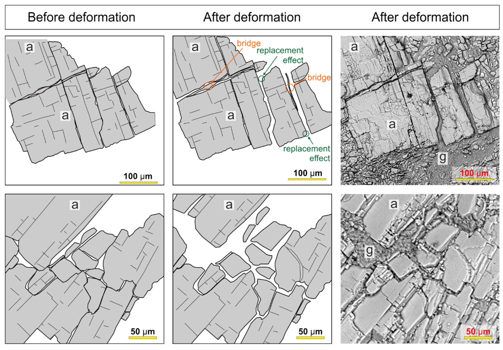
10.1. Fracturing and Expansive Hydration

Ancient anhydrite rocks, particularly those which were deeply buried, are characterized by a very low porosity ranging from 0 to less than 5%, commonly only about 1% or less [165,166]. Many anhydrites are practically impermeable. Massive anhydrite from Dingwall shows negligible porosity, determined by the helium pycnometry method, reaching values even below 0.1%. Slightly gypsified anhydrite rocks show a higher porosity; for example, in five samples with a gypsum content of up to 10%, the porosity was computed in the range from 0.4% to 2.1%. When the anhydrite is massive, the water is not able to penetrate the rock due to its very low permeability and the gypsification is arrested [167]. As described in the introduction, hydration of anhydrite in the system open to inflow of water is a chemical reaction in which a solid molecular volume increases. It belongs to a group of replacement reactions taking place in the lithosphere, which potentially generate stress sufficient to the fracturing of the massive rocks in the process called reaction-induced fracturing (e.g., [168,169,170], with references therein). The crucial feature of these reactions is that at an early stage the reaction-driven fracturing accelerates the rate of reaction by increasing the reaction surface area. The fracturing may occur on a scale of mineral grains (microscale), as well as on a scale of rock samples and outcrops (macroscale). The fracturing related to the hydration of anhydrite can be analysed and better understood according to this currently developing concept [170]. For example, the weathering anhydrites at Dingwall and other similar sites typically show a hierarchical order of fractures and associated gypsum veins pattern with common fractures or veins meeting at angles close to 90° (Figure 4a) ([35], Abb. 5), which is characteristic of the fracture-induced reactions [169,171,172,173,174].
The fracturing accelerating the hydration recorded at Dingwall is interpreted as being driven mainly by displacive growth and the crystallization pressure of gypsum which is a product of hydration. Undoubtedly the displacive growth of gypsum leading to the generation and opening of the fractures is so effective because this mineral is the product of the described hydration reaction. As such a product, it requires more space for in situ formation than the volume of the dissolving massive anhydrite (with negligible porosity), being a solid substrate of the hydration reaction.
We suppose that at the nano- or microscale, the displacement and fracturing process can start in the dissolution pits at the surface of the anhydrite grains in a way similar to some volume-increasing replacement dissolution-precipitation reactions ([174], with references therein). “If the supersaturation with respect to the precipitating phase is high, there will be enough chemical energy available for the precipitating material to exert a mechanical stress on the reacting grain, and cause fracturing, when precipitation is confined within dissolution pits and wedges…” [174] (p. 31). A nanometre-scale confined water solution film between the anhydrite and gypsum crystals will allow the reaction to continue. The shape or pattern of anhydrite etch pits is generally parallel to their cleavage planes (e.g., [155,175,176]). Displacive crystallization of gypsum initiated within such pits can lead to or facilitate the splitting and fracturing of anhydrite along the three perpendicular directions of cleavage (as recorded at Dingwall, Pisky and elsewhere) by the growth of gypsum initiated within such pits (see Figure 7a in [174] for comparison).
As already stated, the fracturing recorded in the studied weathering zone is not only the result of hydration. It can be also caused by some other factors of physical weathering that are active at this site; for example, those related to frost weathering (e.g., [177]). It is known that many fracture-generating factors operate in the weathering zone and, as a rule, they do not act separately, but together.
Aside from natural factors, there are also additional artificial (anthropogenic) factors causing fracturing. These factors have been acting since the beginning of the quarry operation. The volume increase (swelling) of the weathering anhydrites at the quarry bottom could be initiated by the brittle failure of unloaded rocks [178,179,180] and the fact that “after excavation, stresses are reduced around the excavation to a value lower than the crystallization pressure of gypsum, enabling gypsum precipitation and, thus, swelling” [20] (p. 1542). Fractures could be also produced directly by machines working during exploitation.

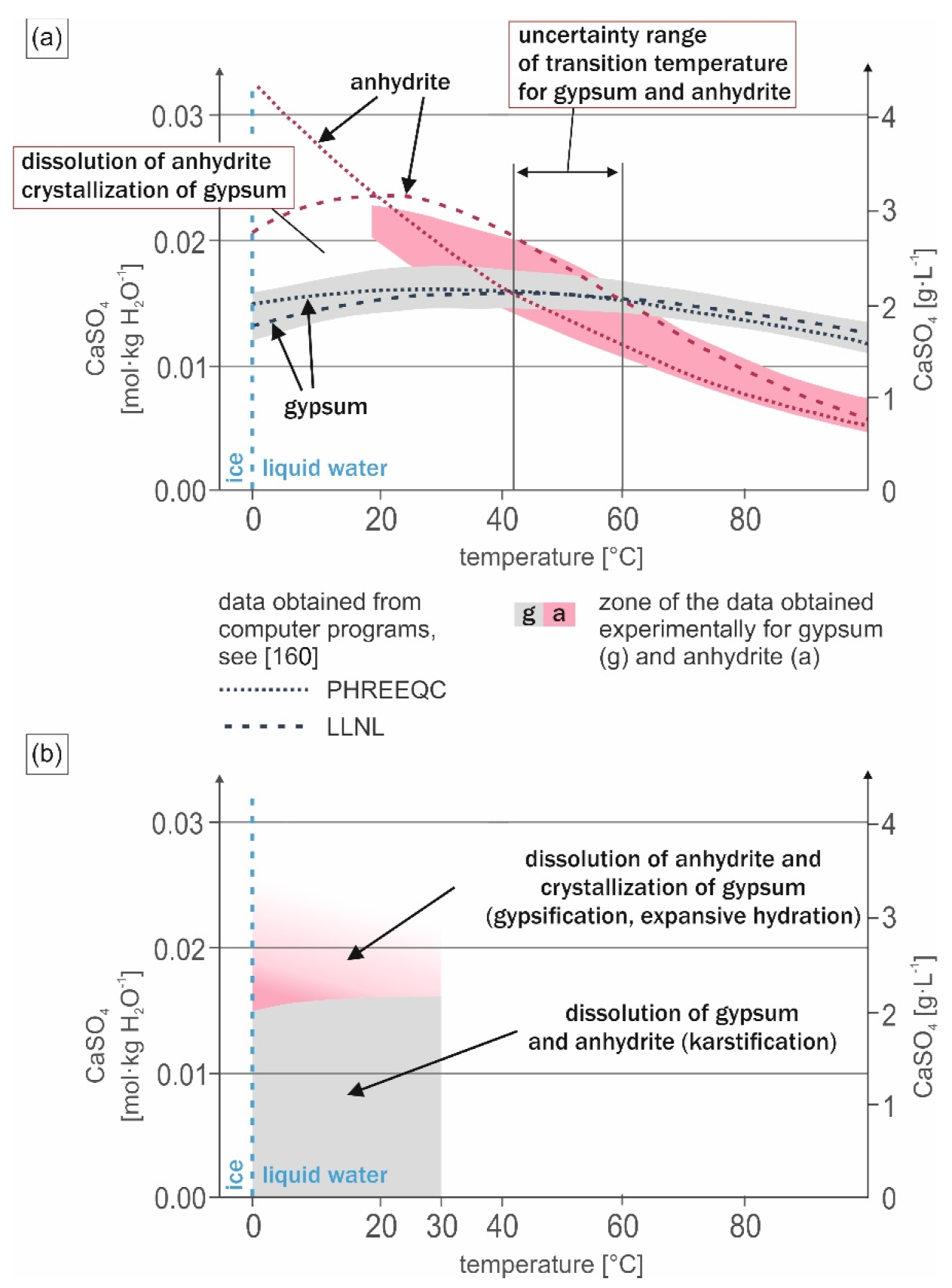
10.2. Advance of Gypsification and Related Processes

The volume increase at Dingwall is evidenced by the presence of deformations visible macroscopically, as domes, tepee-shaped forms (Figure 1c,d) and associated open fractures (Figure 1d, Figure 3, Figure 4 and Figure 5i–l), but also microscopically in the form of similar fractures and fissures (Figure 6n), and, in particular, by the structures indicating the separation of anhydrite crystals and fragments of crystals by the displacive growth of gypsum in mesh fabric (Figure 6l and Figure 7). On the other hand, locally occurring undeformed pseudomorphs of gypsum after anhydrite (Figure 6h,j) evidence that the transformation of anhydrite into gypsum was equal-volume in these places (Hutchins in [153]), [5]. Thus the degree of volume increase of gypsified anhydrites is spatially differentiated and in places is close to 0, which means that the rock remains undeformed at such places. However, in many cases, we were unable to assess which mechanisms of anhydrite gypsification dominate in the rock: displacement, replacement or cementation by gypsum, and, consequently, it was difficult or impossible to estimate the percentage of the volume increase.
Locally observed pseudomorphic or partly pseudomorphic replacement of anhydrite by gypsum indicating replacive growth without volume change [65] suggests the escape of some calcium sulphate solution from that place (e.g., [14,15]). The “escaping” calcium sulphate could probably crystallize in the form of gypsum cement filling in the nearby fractures or other pore spaces. Such gypsum cements enhance the effect of self-sealing, contributing to the complete closure of the pore spaces, blocking the contact of anhydrite with water and thus inhibiting and stopping the hydration process. Sealing by direct crystallization of gypsum on anhydrite reduces the reactive surface area of the crystals and thus inhibits anhydrite dissolution [111]. Complete sealing of anhydrite by newly crystallized gypsum slows down or even stops the dissolution of anhydrite, which can be removed only by diffusion, which is effective only on very short distances [110]. Consequently, also the crystallization of secondary gypsum (gypsification) can be arrested.
In general, the crystallization of gypsum in the anhydrite weathering zone can occur in situ at the place where the anhydrite was dissolved, or outside the dissolved anhydrite in other parts of the rock. At Dingwall, the first type of crystallization is clearly dominant, as evidenced by the predominant fine crystalline gypsum of anhedral habit replacing or displacing the anhydrite crystals or their fragments. On the other hand, gypsum in the form of euhedral crystals forming cement was identified in smaller quantities, and their euhedral habit testifies to crystallization in free space and without interaction with anhydrite at time of its formation. The amount of gypsum cement can indicate a degree of escaping excess calcium sulphate.
The porosity and permeability of the rocks have the greatest influence on the course of gypsification. As outlined above, there are two opposite processes which control the permeability of the weathering anhydrite and advance of gypsification. Fracturing and dissolution by infiltrating fresh water enhance the permeability and drive the gypsification. Gypsum crystallization leading to self-sealing effect decreases the permeability and inhibits the gypsification. Since fracturing can always result from constantly active external factors related to physical weathering; self-sealing will not stop the gypsification so it will continue until complete dissolution and hydration of the anhydrite in the weathering zone. It is expected that at the end of these processes, the dissolution of gypsum will be the dominant process which will lead to development of typical karst on the surface and within the entirely gypsified anhydrite massif.

11. Summary

The weathering of anhydrite deposits exposed at the bottom of the Dingwall quarry leads to their hydration and gypsification, which is associated with the significant volume increase and formation of peculiar hydration relief with ridges, tepee structures and domes, as well as unique hydration caves (Quellungshöhlen).
Petrographic analysis of the zone of the expansive hydration revealed complex structures and the fabric of the gypsum-anhydrite rocks reflects the two drastic transformations they underwent after the deposition. Their primary protolith—formed at the bottom of evaporite basin—was most likely gypsum, which in the first stage of diagenesis turned into anhydrite. At present this anhydrite is hydrated, transforming into gypsum in the weathering zone. The structures and fabric of the rocks, with the exception of layering, no longer reflect the original features of the gypsum deposits, but are the product of overlapping diagenetic and weathering processes.
At the microscopic level the following zones of gypsification can be distinguished, going through the unweathered massive anhydrite (commonly occurring as blocks or nodules similar to corestones):
-
zone of massive to porous anhydrite,
-
zone of anhydrite penetrated by gypsum veinlets separating the crystals and their fragments (commonly along cleavage planes),
-
zone of gypsum with scattered anhydrite relics, and
-
gypsum zone without anhydrite.
The spatial arrangement of these zones indicates the direction and the magnitude of the ongoing gypsification process.
The crystallization of gypsum took place mainly in situ in the place of occurrence of anhydrite crystals by replacement and displacive growth, but also in the empty pore spaces in the form of cement. Gypsum cements commonly infill fractures and fissures and as a rule, are more coarse-crystalline than the replacive-displacive gypsum.
Features of displacive growth exhibited by the gypsum permit to prove that the cause of the volume increase was crystallization pressure exerted by that mineral on its surroundings. Crystallization pressure readily leads to deformations and volume increase in the poorly confined environment of the weathering zone susceptible to upward expansion. Most likely, gypsum crystallization pressure is also the cause of fracturing opening access of water to the massive unweathered anhydrite bedrock and driving its further hydration and gypsification.
Based on the macroscopic and petrographic observations, a model of anhydrite gypsification was presented, showing basic structural changes of massive anhydrite bedrock in its way to fully gypsified rock. The fracturing of the rock (due to ongoing mechanical weathering, expansive hydration or some other factors) is the starting stage in this model, followed by the stage of inflow or infiltration of meteoric water and dissolution of anhydrite rock, along with the opening fractures. When the level of saturation of gypsum is overpassed in the pore water solutions, this mineral is crystallizing at the expense of dissolving anhydrite in the next dissolution-crystallization stages, which are connected with the gradual volume increase. Displacive growth and the crystallization pressure of gypsum can cause additional fracturing, accelerating the hydration process which will continue until the whole anhydrite will be dissolved. The gypsification process can be locally significantly inhibited due to the self-sealing effect; by clogging the fissures and pore spaces around the massive anhydrite by crystallizing gypsum.
The process of anhydrite hydration is a two-stage reaction: dissolution of anhydrite and crystallization of gypsum. For the open system this reaction can lead to a significant volume increase because molecular volume of the solid product (gypsum) is greater that the molecular volume of the solid substrate (anhydrite). Such a reaction belongs to the replacement reactions, which potentially generate stress and fracturing (the so-called reaction driven fracturing [170]).
The expansive hydration of anhydrite taking place at Dingwall is possible due to the optimal environmental conditions in the weathering zone. Within the temperature range from 0 °C (i.e., lower temperature limiting the presence of fresh liquid water) to ca 30 °C (estimated temperature in the summer), the solubility (equilibrium concentration) of gypsum is lower than the solubility (equilibrium concentration) of anhydrite. Such conditions mean that the solution is saturated and slightly supersaturated with respect to gypsum (unable to dissolve gypsum), and is at the same time undersaturated with respect to anhydrite (able to dissolve this mineral). The solution close to saturation with anhydrite remains significantly supersaturated with respect to gypsum and gypsum can readily precipitate from such a solution. Thus, simultaneous dissolution of the anhydrite and crystallization of the gypsum can take place in such a solution. From the thermodynamic point of view, the system will tend to crystallization of the mineral of the lower solubility, i.e., gypsum, which is more stable in the given conditions and it is the dissolving anhydrite that provides the solution supersaturated with gypsum in this process.
Expansive hydration of anhydrite is a highly undesirable process when occurring in industrial or urban areas, where ground swelling and heave lead to the disintegration of buildings, tunnels, roads, etc. [20]. It takes place, not only in the weathering zone (like at Dingwall), but also in the deeper subsurface below the groundwater table, e.g., at depth from which geothermal energy is taken [25]. The present petrographic study, which documents the features of displacive growth of gypsum crystals within gypsified anhydrites, fully confirms the current views of the researchers investigating these destructive processes. We also conclude that the basic direct cause of the expansion is the crystallization of gypsum.

Author Contributions

Conceptualization, A.J., M.B., D.Ł. and F.V.; data curation, A.J., D.Ł. and F.V.; formal analysis, M.B.; funding acquisition, A.J.; methodology, A.J., M.B., D.Ł. and F.V.; project administration, A.J.; software, A.J.; supervision, M.B.; visualization, A.J. and M.B.; writing–original draft, A.J. and M.B. All authors have read and agreed to the published version of the manuscript.

Funding

This research was funded by Ministry of Higher Education and Science, project within the ‘Diamond Grant’ programme, grant no. 0002/DIA/2017/46.

Data Availability Statement

The datasets presented in this study can be found at: http://hydrationcaves.com (accessed on 8 December 2021). The data presented in this study are also available on request from the corresponding authors.

Acknowledgments

The authors would like to acknowledge the Dingwall quarry owners for enabling the research work at the site, and Robert Ryan from the Nova Scotia Department of Energy and Mines for the information provided. The authors are thankful to Janet Connor and John Connor for the accommodation and support during field expeditions to the Dingwall quarry. The authors thank the following persons for their help in conducting the analyses: Tomasz Cygan and Jarosław Woźniak (Warsaw University of Technology)—for study of samples with application of helium pycnometry, Grzegorz Kaproń (Faculty of Geology, University of Warsaw)—for investigation of rock samples using XRD, Jakub Kotowski and Marcin Łącki (Faculty of Geology, University of Warsaw)—for assistance with usage of scanning electron microscopy (SEM-EDS), Agata Królikowska (Faculty of Chemistry, University of Warsaw)—for samples analysis with employment of Raman spectroscopy, Krzysztof Nejbert (Faculty of Geology, University of Warsaw)—for support during preparation of samples, and Grzegorz Widlicki (Faculty of Geology, University of Warsaw)—for preparation of thin sections. The authors also thank the three anonymous reviewers for their remarks which improved the paper.

Conflicts of Interest

The authors declare no conflict of interest.

References

  1. Sonnenfeld, P. Brines and Evaporites; Academic Press Inc.: Orlando, FL, USA, 1984; pp. 1–613. [Google Scholar]
  2. Zanbak, C.; Arthur, R.C. Geochemical and engineering aspects of anhydrite/gypsum phase transitions. Bull. Assoc. Eng. Geol. 1986, 23, 419–433. [Google Scholar] [CrossRef]
  3. Muir, J.L. Anhydrite–gypsum problem of Blaine Formation, Oklahoma. Am. Assoc. Petr. Geol. Bull. 1934, 18, 1297–1312. [Google Scholar] [CrossRef]
  4. Ham, W.E. Economic geology and petrology of gypsum and anhydrite in Blaine County. Okla. Geol. Surv. Bull. 1962, 89, 100–151. [Google Scholar]
  5. Holliday, D.W. The petrology of secondary gypsum rocks: A review. J. Sediment. Petrol. 1970, 40, 734–744. [Google Scholar] [CrossRef]
  6. Kulstad, R.O.; Fairchild, P.; McGregor, D. Gypsum in Kansas. State Geol. Surv. Kans. Bull. 1956, 113, 1–110. [Google Scholar]
  7. Parfenov, S.I. Specific features in anhydrite gypsification. Lithol. Miner. Resour. Litol. I Polezn. Iskopayemyie 1967, 3, 117–127. (In Russian) [Google Scholar]
  8. Lugli, S. Timing of post-depositional events in the Burano Formation of the Secchia valley Upper Triassic, Northern Apennines, clues from gypsum-anhydrite transitions and carbonate metasomatism. Sediment. Geol. 2001, 140, 107–122. [Google Scholar] [CrossRef]
  9. Goldman, M.I. Deformation, metamorphism, and mineralization in gypsum-anhydrite cap rock Sulphur salt dome, Louisiana. Geol. Soc. Am. Mem. 1952, 50, 1–164. [Google Scholar]
  10. Sharpe, R.D. Effects of karst processes on gypsum mining. Evaporite Karst and Engineering/Environmental Problems in the United States. Okla. Geol. Surv. Circ. 2003, 109, 31–40. [Google Scholar]
  11. Anderson, R.Y.; Kirkland, D.W. Intrabasin varve correlation. Geol. Soc. Am. Bull. 1966, 77, 241–256. [Google Scholar] [CrossRef]
  12. Grabau, A.W. Principles of Stratigraphy; A.G. Seiler and Company: New York, NY, USA, 1913; pp. 1–1185. [Google Scholar]
  13. Grabau, A.W. Geology of the Non-metallic Mineral Deposits Other than Silicates. Principles of Salt Deposition; McGraw-Hill Book Company, Inc.: New York, NY, USA, 1920; Volume 1, pp. 1–435. [Google Scholar]
  14. Holliday, D.W. Secondary gypsum in Middle Carboniferous rocks of Spitsbergen. Geol. Mag. 1967, 104, 171–177. [Google Scholar] [CrossRef]
  15. Ortí, F.C. Aproximación al estudio petrográfico de las microestructuras de las rocas de yeso secundario y a su origen. Inst. Investig. Geol. Diput. Prov. Univ. Barc. Rev. 1977, 32, 87–152. [Google Scholar]
  16. Freyer, D.; Voigt, W. Crystallization and phase stability of CaSO4 and CaSO4–based salts. Monatsh. Chem. 2003, 134, 693–719. [Google Scholar] [CrossRef]
  17. Amadi, F.O.; Major, R.P.; Baria, L.R. Origin of gypsum in deep carbonate reservoirs: Implications for hydrocarbon exploration and production. Am. Assoc. Petr. Geol. Bull. 2012, 96, 375–390. [Google Scholar] [CrossRef]
  18. Reimann, M. Geologisch-lagerstättenkundliche und mineralogische Untersuchen zur Vergipsung und Volumenzunahme der Anhydrite verschiedener geologischer Formationen unter natürlichen und labormäßigen Bedingungen. Geol. Jahrb. 1991, 97, 21–125. [Google Scholar]
  19. Berdugo de Moya, I.R.; Alonso Pérez de Ágreda, E.E.; Romero Morales, E.; Gens Solé, A. Tunnelling and swelling in Triassic sulphate-bearing rocks. Part I–Case studies from Baden-Württemberg. Rev. Épsilon 2009, 12, 13–37. [Google Scholar]
  20. Butscher, C.; Mutschler, T.; Blum, P. Swelling of clay-sulfate rocks: A review of processes and controls. Rock Mech. Rock Eng. 2016, 49, 1533–1549. [Google Scholar] [CrossRef]
  21. Jarzyna, A.; Bąbel, M.; Ługowski, D.; Vladi, F.; Yatsyshyn, A.; Olszewska-Nejbert, D.; Nejbert, K.; Bogucki, A. The unique hydration caves and recommended photogrammetric methods for their documentation. Geoheritage 2020, 12, 1–15. [Google Scholar] [CrossRef] [Green Version]
  22. Ramon, T.A. Expansion Mechanisms in Sulphated Rocks and Soils. Ph.D. Thesis, Universitat Politècnica de Catalunya, Barcelona, Spain, 2014; pp. 1–239. [Google Scholar]
  23. Alonso, E.E.; Berdugo, I.R.; Ramon, A. Extreme expansive phenomena in anhydritic-gypsiferous claystone: The case of Lilla tunnel. Géotechnique 2013, 63, 584–612. [Google Scholar] [CrossRef]
  24. Sass, I.; Burbaum, U. Damage to the historic town of Staufen (Germany) caused by geothermal drillings through anhydrite-bearing formations. Acta Carsologica 2010, 39, 233–245. [Google Scholar] [CrossRef] [Green Version]
  25. Fleuchaus, P.; Blum, P. Damage event analysis of vertical groundsource heat pump systems in Germany. Geotherm. Energy 2017, 5, 1–15. [Google Scholar] [CrossRef] [Green Version]
  26. Hunt, C.O.; Gale, S.J.; Gilbertson, D.D. The UNESCO Libyan Valley Survey IX: Anhydrite and limestone karst of the Tripolitanian pre-desert. Libyan Stud. 1985, 16, 1–13. [Google Scholar] [CrossRef]
  27. Holliday, D.W. Early diagenesis in Middle Carboniferous nodular anhydrite of Spitsbergen. Proc. Yorks. Geol. Soc. 1968, 36, 277–283, 292; discussion (with Kent P.E., West I.M., Hemingway J.E., Shearman D.J., Kinsman D.J.J.), 283–292. [Google Scholar] [CrossRef]
  28. Mossop, G.D.; Shearman, D.J. Origin of secondary gypsum rocks. Trans. Inst. Min. Metall. Sec. B Appl. Earth Sci. 1973, 82, B147–B154. [Google Scholar]
  29. Reimann, M.; Vladi, F. Zur Entwicklung der sog. Zwergenkirche am Sachsenstein bei Walkenried, Landkreis Osterode am Harz, Niedersachsen und vergleichende Beobachtungen zur rezenten Entstehung von Quellungshöhlen in einem aufgelassenen Gipssteinbruch bei Dingwall, Nova Scotia, Kanada. Mitt. Verb. Dtsch. Höhlen- Karstforscher 2003, 49, 75–77. [Google Scholar]
  30. Yushkin, N.P. Supergenesis of Carboniferous anhydrites of Novaya Zemlya. Polar Geogr. Geol. 1994, 18, 33–43. [Google Scholar] [CrossRef]
  31. Bąbel, M.; Olszewska-Nejbert, D.; Ługowski, D.; Nejbert, K.; Jacyszyn, A. Petrogenesis of the zone of present day anhydrite weathering at Pisky near Lviv. In The Weathering of Anhydrite and Gypsum Rocks; Bąbel, M., Olszewska-Nejbert, D., Nejbert, K., Eds.; GIMPO Agencja Wydawniczo-Poligraficzna: Warsaw, Poland, 2020; pp. 145–213, (In Polish with English summary). [Google Scholar] [CrossRef]
  32. Ługowski, D.; Bąbel, M. Distribution of gypsum content in anhydrite hydration dome from Pisky near Lviv and its development. In The Weathering of Anhydrite and Gypsum Rocks; Bąbel, M., Olszewska-Nejbert, D., Nejbert, K., Eds.; GIMPO Agencja Wydawniczo-Poligraficzna: Warsaw, Poland, 2020; pp. 135–144, (In Polish with English summary). [Google Scholar] [CrossRef]
  33. Stenson, R.E. The Morphometry and Spatial Distribution of Surface Depressions in Gypsum, with Examples from Nova Scotia, Newfoundland and Manitoba. Ph.D. Thesis, McMaster University, Hamilton, ON, Canada, 1990; pp. 1–134. [Google Scholar]
  34. Vladi, F.; Bąbel, M. Recent growth and decay of the hydration (swelling) caves in the former gypsum quarry of Dingwall in Cape Breton, Nova Scotia, Canada. In The Weathering of Anhydrite and Gypsum Rocks; Bąbel, M., Olszewska-Nejbert, D., Nejbert, K., Eds.; GIMPO Agencja Wydawniczo-Poligraficzna: Warsaw, Poland, 2020; pp. 223–232. [Google Scholar]
  35. Vladi, F.; Bąbel, M.; Jarzyna, A. Wachstum und Zerfall rezenter Quellungshöhlen im ehemaligen Gipssteinbruch von Dingwall in Cape Breton, Nova Scotia, Kanada, nebst anmerkungen zum dortigen Sulfatkarst und dem Forschungsstand. Abh. Zur Karst- Und Höhlenkunde 2021, 40, 113–128. [Google Scholar]
  36. Stenson, R.E.; Ford, D.C. Rillenkarren on gypsum in Nova Scotia. Geogr. Phys. Quatern. 1993, 47, 239–243. [Google Scholar]
  37. Bath, A.H.; Darling, W.G.; George, I.A.; Milodowski, A.E. 18O/16O and 2H/1H changes during progressive hydration of a Zechstein anhydrite formation. Geochim. Cosmochim. Acta 1987, 51, 3113–3118. [Google Scholar] [CrossRef]
  38. Reimann, M. Zur Vergipsung der Zechsteinanhydrite Nordwestdeutschlands. Zbl. Geo. Pal. 1991, 4, 1201–1210. [Google Scholar]
  39. Webb, T.C. Geology and economic development of early Carboniferous marine evaporates, southeastern New Brunswick. New Brunswick Department of Natural Resources. In Lands, Minerals and Petroleum Division; Field Guide No. 6; Lands, Minerals and Petroleum Division, Department of Natural Resources: New Brunswick, NJ, Canada, 2010; pp. 1–71. [Google Scholar]
  40. Kottek, M.; Grieser, J.; Beck, C.; Rudolf, B.; Rubel, F. World map of the Köppen-Geiger climate classification updated. Meteorol. Z. 2006, 15, 259–263. [Google Scholar] [CrossRef]
  41. Climate-data.org. Available online: https://en.climate-data.org/north-america/canada/nova-scotia/dalem-lake-98946/ (accessed on 18 September 2021).
  42. Connor, J.; (Cape North, NS, Canada). Personal communication. 2019. [Google Scholar]
  43. Gregory, D.J. Gypsum location map and drill hole sections of boreholes through gypsum in Nova Scotia. 1974; 1–37. [Google Scholar]
  44. Moore, R.G. Lithostratigraphic units in the upper part of the Windsor Group, Minas sub-basin, Nova Scotia. Geol. Assoc. Can. 1967, 4, 1–22. [Google Scholar]
  45. MacNeil, L.A.; Pufahl, P.K.; James, N.P. Deposition of a saline giant in the Mississippian Windsor group, Nova Scotia, and the nascent late Paleozoic ice age. Sediment. Geol. 2018, 363, 118–135. [Google Scholar] [CrossRef]
  46. Bell, W.A. Horton-Windsor district, Nova Scotia. In Geological Survey of Canada, Memoir 155; King’s Printer: Ottawa, OT, Canada, 1929; pp. 1–268. [Google Scholar]
  47. Neale, E.R.W. Geology, Pleasant Bay, Nova Scotia, Map 1119A; Neale, E.R.W., Ed.; Geological Survey of Canada, Department of Mines and Technical Surveys: Ottawa, ON, Canada, 1963.
  48. Neale, E.R.W. Geology, Dingwall, Nova Scotia, Map 1124A; Neale, E.R.W., Ed.; Geological Survey of Canada, Department of Mines and Technical Surveys: Ottawa, ON, Canada, 1963.
  49. Adams, G.C. Gypsum and anhydrite resources in Nova Scotia. Econ. Geol. Ser. 1991, 91, 1–293. [Google Scholar]
  50. Grant, D.R. Late Quaternary movement of Aspy Fault, Nova Scotia. Can. J. Earth Sci. 1990, 27, 984–987. [Google Scholar] [CrossRef]
  51. Grant, D.R. Quaternary geology. Geol. Surv. Can. 1994, 482, 1–159. [Google Scholar] [CrossRef]
  52. Moseley, M. Genesis of schlottenkarren on the Avon Peninsula of Nova Scotia (Canada) with implications for the geochronology of evaporite karsts and caves of Atlantic Canada. Int. J. Speleol. 2017, 46, 267–276. [Google Scholar] [CrossRef] [Green Version]
  53. Beales, F.W.; Oldershaw, A.E. Evaporite-solution brecciation and Devonian carbonate reservoir porosity in Western Canada. Am. Assoc. Petr. Geol. Bull. 1969, 53, 503–512. [Google Scholar] [CrossRef]
  54. Ługowski, D.; Bąbel, M.; Nejbert, K. Simple method of approximate determination of the quantitative mineralogical composition of gypsum-anhydrite rocks (compared to other analytical methods). In The Weathering of Anhydrite and Gypsum Rocks; Bąbel, M., Olszewska-Nejbert, D., Nejbert, K., Eds.; GIMPO Agencja Wydawniczo-Poligraficzna: Warsaw, Poland, 2020; pp. 125–134, (In Polish with English summary). [Google Scholar] [CrossRef]
  55. Brodie, K.; Fettes, D.; Harte, B. Structural terms including fault rock terms. In Metamorphic Rocks: A Classification and Glossary of Terms. Recommendations of the International Union of Geological Sciences Subcommission on the Systematics of Metamorphic Rocks; Fettes, D., Desmons, J., Eds.; Cambridge University Press: Cambridge, UK, 2007; pp. 24–31. [Google Scholar]
  56. Maiklem, W.R.; Bebout, D.G.; Glaister, R.P. Classification of anhydrite—A practical approach. Bull. Can. Petrol. Geol. 1969, 17, 194–233. [Google Scholar] [CrossRef]
  57. Garrison, R.E.; Schreiber, B.C.; Bernoulli, D.; Fabricius, F.H.; Kidd, R.B.; Mélières, F. Sedimentary petrology and structures of Messinian evaporitic sediments in the Mediterranean Sea, Leg 42A, Deep Sea Drilling Project. In Initial Reports of the Deep Sea Drilling Project; Hsü, K.J., Montadert, L., Eds.; U.S. Government Printing Office: Washington, WA, USA, 1978; Volume 42, pp. 571–611. [Google Scholar] [CrossRef]
  58. Meyer, F.O. Anhydrite Classification According to Structure; Carbonate Research Consulting: Conifer, CO, USA, 2016; pp. 1–21. Available online: https://linkd.pl/pcru2 (accessed on 8 November 2021).
  59. Shawkat, M.G. The Sedimentology of the Lower Fars Formation (Miocene) of Northern Iraq. Ph.D. Thesis, University of Newcastle upon Tyne, Newcastle upon Tyne, UK, 1979; pp. 1–164. Available online: https://theses.ncl.ac.uk/dspace/bitstream/10443/597/1/Shawkat79.pdf. (accessed on 8 November 2021).
  60. Ciarapica, G.; Passeri, L.; Schreiber, B.C. Una proposta di classificazione delle evaporiti solfatiche. Geologica Rom. 1985, 24, 219–232. [Google Scholar]
  61. Forkner, R.M. An integrated system for macro-scale anhydrite classification. Geol. Q. 2010, 54, 423–430. [Google Scholar]
  62. Bathurst, R.G.C. Carbonate Sediments and Their Diagenesis, 2nd ed.; Developments in Sedimentology; Elsevier: Amsterdam, The Netherlands, 1975; Volume 12, pp. 1–658. [Google Scholar]
  63. Friedman, G.M. Terminology of crystallization textures and fabrics in sedimentary rocks. J. Sediment. Petrol. 1965, 35, 643–655. [Google Scholar] [CrossRef]
  64. Neuendorf, K.K.E.; Mehl, J.P., Jr.; Jackson, J.A. (Eds.) Glossary of Geology, 5th ed.; American Geosciences Institute: Alexandria, VA, USA, 2005; pp. 1–779. [Google Scholar]
  65. Lindgren, W. The nature of replacement. Econ. Geol. 1912, 7, 521–535. [Google Scholar] [CrossRef]
  66. Bastin, E.S.; Graton, L.C.; Lindgren, W.; Newhouse, W.H.; Schwartz, G.M.; Short, M.N. Criteria of age relations of minerals, with especial reference to polished sections of ores. Econ. Geol. 1931, 26, 561–610. [Google Scholar] [CrossRef]
  67. Ramberg, H. The Origin of Metamorphic and Metasomatic rocks: A Treatise on Recrystallization and Replacement in the Earth’s Crust; The University of Chicago Press: Chicago, IL, USA, 1952; pp. 1–317. [Google Scholar]
  68. Folk, R.L. Some aspects of recrystallization in ancient limestones. Dolomitization and Limestone Diagenesis. In Society of Economic Paleontologists and Mineralogists Special Publication; Pray, L.C., Murray, R.D., Eds.; SEPM Society for Sedimentary Geology: Tulsa, OK, USA, 1965; No. 13; pp. 14–48. [Google Scholar] [CrossRef]
  69. Ward, W.B.; Reeder, R.J. The use of growth microfabrics and transmission electron microscopy in understanding replacement processes in carbonates. In Carbonate Microfabrics; Rezak, R., Lavoie, D.L., Eds.; Springer: New York, NY, USA, 1993; pp. 253–264. [Google Scholar] [CrossRef]
  70. Franklin, J.A. Suggest methods for determining water content, porosity, density, absorption and related properties and swelling and slake-durability index properties. Int. J. Rock. Mech. Min. 1979, 16, 141–156. [Google Scholar]
  71. Anovitz, L.M.; Cole, D.R. Characterization and analysis of porosity and pore structures. Rev. Mineral. Geochem. 2015, 80, 61–164. [Google Scholar] [CrossRef] [Green Version]
  72. Pye, K.; Krinsley, D.H. Petrographic examination of sedimentary rocks in the SEM using backscattered electron detectors. J. Sediment. Petrol. 1984, 54, 877–888. [Google Scholar] [CrossRef]
  73. Jordan, P.G.; Düggelin, M.; Mathys, D.; Guggenheim, R. Gypsum-anhydrite differentiation by SEM using the back-scattered electron-signal. J. Sediment. Res. 1991, 61, 616–618. [Google Scholar] [CrossRef]
  74. Papezik, V.S.; Fong, C.C.K. Howlite and ulexite from the Carboniferous gypsum and anhydrite beds in western Newfoundland. Can. Mineral. 1975, 13, 370–376. [Google Scholar]
  75. Goodman, N.R. Gypsum and anhydrite in Nova Scotia. In Nova Scotia Department of Mines; Society of Economic Geologists Inc.: Halifax, NS, Canada, 1952; pp. 1–71. [Google Scholar]
  76. Nova Scotia Well Logs Database. Available online: https://novascotia.ca/natr/meb/download/dp430.asp (accessed on 3 November 2021).
  77. Baechler, F.; Boehner, R. Karst geology and hydrogeology of Cape Breton Island, Nova Scotia: An overview. Can. J. Earth Sci. 2014, 51, 701–714. [Google Scholar] [CrossRef]
  78. Wilder, F.A. Gypsum and anhydrite. Am. Min. 1928, 13, 476–480. [Google Scholar]
  79. Ford, D. Principal features of evaporite karst in Canada. Carbonate Evaporite 1997, 12, 15–23. [Google Scholar] [CrossRef]
  80. Barnaby, R.J. Quantitative image analysis for geologic core description. J. Sediment. Res. 2017, 87, 460–485. [Google Scholar] [CrossRef]
  81. Langbein, R. The Zechstein sulphates: The state of art. In The Zechstein Facies in Europe; Lecture Notes in Earth, Sciences; Peryt, T.M., Ed.; Springer: Berlin/Heidelberg, Germany, 1987; Volume 10, pp. 143–188. [Google Scholar]
  82. Bąbel, M.; Kasprzyk, A. Gypsum ooids from the Middle Miocene (Badenian) evaporites of southern Poland. Acta Geol. Pol. 1990, 40, 215–239. [Google Scholar]
  83. Mossop, G.D. The evaporites of the Ordovician Baumann Fiord Formation, Ellesmere Island, Arctic Canada. Geol. Surv. Can. Bull. 1979, 298, 1–52. [Google Scholar]
  84. Fabre, D.; Dayre, M. Proprietes geotechniques de gypses et anhydrites du Trias des Alps de Savoie (France). Bull. Int. Assoc. Eng. Geol. 1982, 25, 91–98. [Google Scholar] [CrossRef]
  85. Dronkert, H. Diagenesis of Triassic evaporites in northern Swizterland. Eclogae Geol. Helv. 1987, 80, 397–413. [Google Scholar] [CrossRef]
  86. Schreiber, B.C.; Helman, M.L. Criteria for distinguishing primary evaporite features from deformation features in sulphate evaporites. J. Sediment. Res. 2005, 75, 525–533. [Google Scholar] [CrossRef]
  87. Holliday, D.W. Field excursion to the Brooks and Bito gypsum quarries, eastern St. Andrew. J. Geol. Soc. Jam. 1970, 11, 36–41. [Google Scholar]
  88. Holliday, D.W. Origin of Lower Eocene gypsum-anhydrite rocks, southeast St. Andrew, Jamaica. Trans. Inst. Min. Met. 1971, 80, B305–B315. [Google Scholar]
  89. Ortí, F.; Rosell, L.; Playà, E.; Salvany, J.M. Meganodular anhydritization: A new mechanism of gypsum to anhydrite conversion (Palaeogene–Neogene, Ebro Basin, North-east Spain). Sedimentology 2012, 59, 1257–1277. [Google Scholar] [CrossRef]
  90. Shearman, D.J.; Fuller, J.G. Anhydrite diagenesis, calcitization, and organic laminites, Winnipegosis Formation, Middle Devonian, Saskatchewan. Bull. Can. Petrol. Geol. 1969, 17, 496–525. [Google Scholar] [CrossRef]
  91. Zavaritzky, A. Le gypse et l’anhydrite du village Okhlébinino. Bull. Com. Géologique Izvestyia Geol. Kom. 1925, 43, 973–985. (In Russian) [Google Scholar]
  92. Von Gaertner, H.-R. Petrographie und paläogeographische Stellung der Gipse vom Südrande des Harzes. Jahrb. Preußischen Geol. Landesanst. Berl. 1933, 53, 655–694. [Google Scholar]
  93. Anrich, H. Zur Frage der Vergipsung in den Sulfatlagern des Mittleren Muschelkalks und Gipskeupers in Südwestdeutschland. Neues Jahrbuch für Geologie und Paläontologie Anhandlungen 1958, 106, 293–338. [Google Scholar]
  94. Reimann, M. Geologie, Petrographie und Vergipsung der Zechsteinsulfatvorkommen von Stadtoldendorf und Osterode/Harz. Ber. Nat. Ges. Hann. 1987, 129, 57–84. [Google Scholar]
  95. Hauber, L.; Jordan, P.; Madsen, F.; Nüesch, R.; Vögtli, B.; Flückiger, A.; Ko, L.S.C. Tonminerale und Sulfate als Ursache für druckhaftes Verhalten von Gesteinen. In Ursachen und Wirkungen des Quellvorganges; Forschungsauftrag 55/92 und 52/96 (Nr. 4306.01 und 4306.02) auf Antrag des Bundesamtes für Strassenbau, ASTRA 1996/039; Geologisch-Palaeontologisches Institut der Universität Basel, Abt. Praktische Geologie: Basel, Switzerland, 2005; pp. 1–90. [Google Scholar]
  96. Webb, T.C. Geology, Development History, and Exploration Alternatives for Gypsum and Anhydrite Resources Near Hillsborough (Part of NTS 21 H/15), Albert County, Southeastern New Brunswick; Open File 2001-6; New Brunswick Department of Natural Resources and Energy, Minerals and Energy Division: Sussex, NB, Canada, 2002; pp. 1–47.
  97. Ortí, F.C.; Rosell, L.O. Fabricas cristalinas de la anhidrita nodular y laminada. Acta Geol. Hisp. 1981, 16, 235–255. [Google Scholar]
  98. Brown, L.S. Cap-rock petrography. Am. Assoc. Petr. Geol. Bull. 1931, 15, 509–529. [Google Scholar]
  99. Carozzi, A.V. Microscopic Sedimentary Petrography; John Wiley Sons., Inc.: New York, NY, USA, 1960; pp. 1–485. [Google Scholar]
  100. Aleali, M.; Rahimpour-Bonab, H.; Moussavi-Harami, R.; Jahani, D. Environmental and sequence stratigraphic implications of anhydrite textures: A case from the Lower Triassic of the Central Persian Gulf. J. Asian Earth Sci. 2013, 75, 110–125. [Google Scholar] [CrossRef]
  101. Shearman, D.J. Syndepositional and late diagenetic alteration of primary gypsum to anhydrite. In Proceedings of the Sixth International Symposium on Salt, Toronto, ON, Canada, 24–28 May 1983; Schreiber, B.C., Harner, H.R., Eds.; The Salt Institute: Alexandria, VA, USA, 1985; Volume 1, pp. 41–50. [Google Scholar]
  102. West, I.M. Evaporite diagenesis in the Lower Purbeck Beds of Dorset. Proceed. Yorkshire Geol. Soc. 1964, 34, 315–330. [Google Scholar] [CrossRef]
  103. Craig, J.R.; Vaughan, D.J. Ore Microscopy and Ore Petrography, 2nd ed.; John Wiley Sons, Inc.: New York, NY, USA, 1994; pp. 1–434. [Google Scholar]
  104. Taber, S. The origin of veinlets in the Silurian and Devonian strata of central New York. J. Geol. 1918, 26, 56–73. [Google Scholar] [CrossRef]
  105. Mossop, G.D. Anhydrite-Carbonate Cycles of the Ordovician Baumann Fiord Formation, Ellesmere Island, Arctic Canada: A Geological History. Ph.D. Thesis, University of London, London, UK, 1973; pp. 1–231. [Google Scholar]
  106. Marandi, M.; Jahani, D.; Uromeihy, A.; Reihan, M.K. Analysis of structure and textures of anhydrite mineral in Gachsaran Formation in Gotvand area, Iran. Open J. Geol. 2017, 7, 1478–1493. [Google Scholar] [CrossRef] [Green Version]
  107. James, A.N.; Lupton, A.R.R. Gypsum and anhydrite in foundations of hydraulic structures. Geotechnique 1978, 28, 249–272. [Google Scholar] [CrossRef]
  108. Gysel, M. Anhydrite dissolution phenomena: Three case histories of anhydrite karst caused by water tunnel operation. Rock Mech. Rock Eng. 2002, 35, 1–21. [Google Scholar] [CrossRef]
  109. Serafeimidis, K.; Anagnostou, G. The effect of sealing on anhydrite hydration in swelling rocks. In Proceedings of the First International Conference for PhD Students in Civil Engineering, Cluj-Napoca, Romania, 4–7 November 2012; p. 8. [Google Scholar]
  110. Serafeimidis, K.; Anagnostou, G. On the time-development of sulphate hydration in anhydritic swelling rocks. Rock Mech. Rock Eng. 2013, 46, 619–634. [Google Scholar] [CrossRef] [Green Version]
  111. Serafeimidis, K. On the Dissolution, Precipitation and Transport Processes in Sulphatic Swelling Rocks. Ph.D. Thesis, Eidgenössische Technische Hochschule Zürich, Zurich, Switzerland, 2014; pp. 1–228. [Google Scholar]
  112. Wanninger, T.; Pimentel, E.; Anagnostou, G. Experimental investigetions on the self-sealing of anhydritic rock. In Proceedings of the 51st U.S. Rock Mechanics/Geomechanics Symposium, San Francisco, CA, USA, 25–28 June 2017; pp. 1–8. [Google Scholar]
  113. Wanninger-Huber, T.C. Experimental Investigations for the Modelling of Anhydritic Swelling Claystones. Ph.D. Thesis, Eidgenössische Technische Hochschule Zürich, Zürich, Switzerland, 2019; pp. 1–325. [Google Scholar]
  114. Shearman, D.J.; Mossop, G.; Dunsmore, H.; Martin, M. Origin of gypsum veins by hydraulic fracture. Inst. Min. Metall. Trans. Sect. B Appl. Earth Sci. 1972, 81, B149–B155. [Google Scholar]
  115. Hilgers, C.; Urai, J.L. On the arrangement of solid inclusions in fibrous veins and the role of the crack-seal mechanism. J. Struct. Geol. 2005, 27, 481–494. [Google Scholar] [CrossRef]
  116. Richardson, W.A. The fibrous gypsum of Nottinghamshire. Mineral. Mag. J. Mineral. Soc. 1920, 19, 77–95. [Google Scholar] [CrossRef]
  117. Fletcher, R.C.; Merino, E. Mineral growth in rocks: Kinetic–rheological models of replacement, vein formation, and syntectonic crystallization. Geochim. Cosmochim. Acta 2001, 65, 3733–3748. [Google Scholar] [CrossRef]
  118. Bailey, H.B. Hydration factors in gypsum deposits of the Maritime Provinces. In American Institute of Mining and Mettalurgical Engineers; Technical Publication 308; The American Institute of Mining and Metallurgical Engineers: New York, NY, USA, 1930; pp. 1–11. [Google Scholar]
  119. Boyd, J.M.; Currie, J.B. Fracture porosity in alabaster: An experimental model of rock deformation. Bull. Can. Petrol. Geol. 1969, 17, 117–132. [Google Scholar] [CrossRef]
  120. Auvray, C.; Homand, F.; Sorgi, C. The aging of gypsum in underground mines. Eng. Geol. 2004, 74, 183–196. [Google Scholar] [CrossRef]
  121. Putnis, A.; Austrheim, H. Fluid-induced processes: Metasomatism and metamorphism. Geofluids 2010, 10, 254–269. [Google Scholar] [CrossRef]
  122. Lebedev, A.L.; Avilina, I.A. The kinetics of gypso anhydrites dissolution in water: Experimental studies. Mosc. Univ. Geol. Bull. 2019, 74, 429–432. [Google Scholar] [CrossRef]
  123. Lutenegger, A.J.; Wollenhaupt, N.C.; Handy, R.L. Laboratory simulation of shale expansion by induced gypsum growth. Can. Geotech. J. 1979, 16, 405–409. [Google Scholar] [CrossRef]
  124. Shearman, D.J. Displacement of sand grains in sandy gypsum crystals. Geol. Mag. 1981, 118, 303–306. [Google Scholar] [CrossRef]
  125. Verboom, B.; Grealish, G.; Schoknecht, N.; Omar, S. Influence of gravel on the accumulation of pedogenic gypsum in Kuwait. Arid. Land Res. Manag. 2003, 17, 71–84. [Google Scholar] [CrossRef]
  126. Hoover, S.E.; Lehmann, D. The expansive effects of concentrated pyritic zones within the Devonian Marcellus Shale Formation of North America. Q. J. Eng. Geol. Hydrogeol. 2009, 42, 157–164. [Google Scholar] [CrossRef]
  127. Casby-Horton, S.; Herrero, J.; Rolong, N.A. Gypsum soils—Their morphology, classification, function, and landscapes. In Advances in Agronomy; Sparks, D.L., Ed.; Elsevier Academic Press: Amsterdam, The Netherlands, 2015; Volume 130, pp. 231–290. [Google Scholar]
  128. Bundy, W.M. Petrology of gypsum-anhydrite deposits in southwestern Indiana. J. Sediment. Petrol. 1956, 26, 240–252. [Google Scholar] [CrossRef]
  129. Flückiger, A.; Nüesch, R.; Madsen, F.T. Anhydritquellung. In Proceedings of the Jahrestagung DGGT, Regensburg, Germany, 13–14 September 1994; Kohler, E.E., Ed.; Berichte der Deutschen Ton- und Tonmineralgruppe. Deutsche Ton- und Tonmineralgruppe DTTG: Dornburg, Germany, 1994; pp. 146–153. [Google Scholar]
  130. Keulen, N.T.; Den Brok, S.W.J.; Spiers, C.J. Force of crystallisation of gypsum during hydration of anhydrite rock. In Proceedings of the 13th DRT Conference, Deformation Mechanisms, Rheology, and Tectonics, Noordwijkerhout, The Netherlands, 2–4 April 2001; p. 1. [Google Scholar]
  131. Ramon, A.; Olivella, S.; Alonso, E.E. Swelling of a gypsiferous claystone and its modelling. In Proceedings of the 17th International Conference on Soil Mechanics and Geotechnical Engineering, Alexandria, Egypt, 5–9 October 2009; Hamza, M., Shahien, M., El-Mossallam, Y., Eds.; IOS Press: Amsterdam, The Netherlands, 2009; pp. 730–733. [Google Scholar] [CrossRef]
  132. Ramon, A.; Alonso, E.E. Heave of a railway bridge: Modelling gypsum crystal growth. Géotechnique 2013, 63, 720–732. [Google Scholar] [CrossRef]
  133. Serafeimidis, K.; Anagnostou, G. On the crystallisation pressure of gypsum. Environ. Earth. Sci. 2014, 72, 4985–4994. [Google Scholar] [CrossRef] [Green Version]
  134. Khaimov-Malkov, V.Y. Experimental measurement of crystallization pressure. In Growth of Crystals; Shubnikov, A.V., Sheftal, N.N., Eds.; Consultants Bureau, Inc.: New York, NY, USA; Chapman Hall, Ltd.: London, UK, 1959; Volume 2, pp. 14–19. [Google Scholar]
  135. Scherer, G.W. Factors affecting crystallization pressure. In Internal Sulfate Attack and Delayed Ettringite Formation, Proceedings of the International RILEM TC 186-ISA Workshop on Internal Sulfate Attack and Delayed Ettringite Formation, Villars, Switzerland, 4–6 September 2002; Scrivener, K., Skalny, J., Scrivener, K., Skalny, J., Eds.; RILEM Publications: Bagneux, France, 2004; pp. 139–154. ISBN 2-912143-44-46. [Google Scholar]
  136. Flatt, R.J.; Steiger, M.; Scherer, G.W. A commented translation of the paper by C.W. Correns and W. Steinborn on crystallization pressure. Environ. Geol. 2007, 52, 187–203. [Google Scholar] [CrossRef]
  137. Sekine, K.; Okamoto, A.; Hayashi, K. In situ observation of the crystallization pressure induced by halite crystal growth in a microfluidic channel. Am. Mineral. 2011, 96, 1012–1019. [Google Scholar] [CrossRef]
  138. Steiger, M.; Charola, A.E.; Sterflinger, S. Weathering and deterioration. In Stone in Architecture, Properties, Durability, 5th ed.; Siegesmund, S., Snethlage, S., Eds.; Springer: Heidelberg, Germany, 2014; pp. 225–316. [Google Scholar] [CrossRef]
  139. Meldrum, F.C.; O’Shaughnessy, C. Crystallization in confinement. Adv. Mater. 2020, 32, 1–64. [Google Scholar] [CrossRef]
  140. Oguchi, C.T.; Yu, S. A review of theoretical salt weathering studies for stone heritage. Prog. Earth Planet. Sci. 2021, 8, 1–23. [Google Scholar] [CrossRef]
  141. Bard, J.P. Microtextures of Igneous and Metamorphic Rocks; Reidel, D., Ed.; Publishing Company: Dordrecht, The Netherlands, 1986; pp. 1–264. [Google Scholar]
  142. Nahon, D.; Merino, E. Pseudomorphic replacement in tropical weathering: Evidence, geochemical consequences, and kinetic-rheological origin. Am. J. Sci. 1997, 297, 393–417. [Google Scholar] [CrossRef]
  143. Fletcher, R.C.; Merino, E. Mineral growth in rocks: Interacting stress and kinetics in vein growth, replacement, and water-rock interaction. In Water-Rock Interaction, Proceedings of the Tenth International Symposium on Water-Rock Interaction, WRI-10, Villasimius, Italy, 10–15 July 2001; Cidu, R., Ed.; A.A. Balkema: Lisse, The Netherlands, 2001; pp. 161–164. [Google Scholar]
  144. Chen, Q.; You, L.; Kang, Y.; Dou, L.; Sheng, J.J. Gypsum-crystallization-induced fracturing during shale−fluid reactions and application for shale stimulation. Energy Fuels 2018, 32, 10367–10381. [Google Scholar] [CrossRef]
  145. Bell, F.G. A survey of the engineering properties of some anhydrite and gypsum from the north and midlands of England. Eng. Geol. 1994, 38, 1–23. [Google Scholar] [CrossRef]
  146. Zhang, B.; Wang, H.; Wang, L.; Xu, N. Stability analysis of a group of underground anhydrite caverns used for crude oil storage considering rock tensile properties. Bull. Eng. Geol. Environ. 2019, 78, 6249–6265. [Google Scholar] [CrossRef]
  147. Bilgin, N. The cuttability of evaporites. Bull. Int. Assoc. Eng. Geol. 1982, 25, 85–90. [Google Scholar] [CrossRef]
  148. Papadopoulos, Z.; Kolaiti, E.; Mourtzas, N. The efect of crystal size on geotechnical properties of Neogene gypsum in Crete. Q. J. Eng. Geol. 1994, 27, 267–273. [Google Scholar] [CrossRef]
  149. Serafeimidis, K.; Anagnostou, G.; Vrakas, A. Scale effects in relation to swelling pressure in anhydritic claystones. Geomechnics from Micro to Macro. In Proceedings of the TC105 ISSMGE International Symposium on Geomechanics from Micro to Macro, Cambridge, UK, 1–3 September 2014; Soga, K., Kumar, K., Biscontin, G., Kuo, M., Eds.; Taylor Francis Group: London, UK, 2015; Volume 2, pp. 795–800. [Google Scholar]
  150. Imam, R.; Mahmoudi, A.; Farsghoshooni, A. Experimental study of gypsum and anhydrite dissolution due to surface flow. In Proceedings of the GeoEdmonton 2018—71st Canadian Geotechnical Conference and the 13th Joint CGS/IAH-CNC Groundwater Conference, Paper 259. Edmonton, AL, Canada, 23–26 September 2018; p. 10. [Google Scholar]
  151. Kaufmann, G.; Romanov, D. Modelling speleogenesis in soluble rocks: A case study from the Permian Zechstein sequences exposed along the southern Harz Mountains and the Kyffhäuser Hills, German. Acta Carsologica 2019, 48, 173–197. [Google Scholar] [CrossRef] [Green Version]
  152. Rauh, F.; Thuro, K. Investigations on the swelling behavior of pure anhydrites. In Proceedings of the 1st Canada–U.S. Rock Mechanics Symposium, Vancouver, WA, Canada, 27–31 May 2007. [Google Scholar] [CrossRef]
  153. McWhae, J.R.H. The Carboniferous breccias of Billefjorden, Vestspitsbergen. Geol. Mag. 1953, 95, 287–298. [Google Scholar] [CrossRef]
  154. Bell, F.G. Engineering Properties of Soils and Rocks, 3rd ed.; Butterworth-Heinemann Ltd.: Oxford, UK, 1992; pp. 1–345. [Google Scholar]
  155. Pina, C.M. Nanoscale dissolution and growth on anhydrite cleavage faces. Geochim. Cosmochim. Acta 2009, 73, 7034–7044. [Google Scholar] [CrossRef] [Green Version]
  156. Anagnostou, G.; Pimentel, E.; Serafeimidis, K. Swelling of sulphatic claystones–some fundamental questions and their practical relevance. Geomech. Tunn. 2010, 3, 567–572. [Google Scholar] [CrossRef]
  157. Serafeimidis, K.; Anagnostou, G. The solubilities and thermodynamic equilibrium of anhydrite and gypsum. Rock Mech. Rock Eng. 2015, 48, 15–31. [Google Scholar] [CrossRef]
  158. Kontrec, J.; Kralj, D.; Brečević, L. Transformation of anhydrous calcium sulphate into calcium sulphate dihydrate in aqueous solutions. J. Cryst. Growth 2002, 240, 203–211. [Google Scholar] [CrossRef]
  159. Serafeimidis, K.; Anagnostou, G. Simultaneous anhydrite dissolution and gypsum precipitation in a closed swelling rock system. In Proceedings of the 46th US Rock Mechanics/Geomechanics Symposium, Symposium Proceedings, Chicago, IL, USA, 24–27 June 2012; Bobet, A., Ewy, R., Gadde, M., Labuz, J., Pyrak-Nolte, L., Westman, E., Eds.; American Rock Mechanics Association (ARMA): Alexandria, VA, USA, 2012; Volume 3, pp. 2249–2259. [Google Scholar]
  160. Van Driessche, A.E.S.; Stawski, T.M.; Benning, L.B.; Kellermeier, M. Calcium sulfate precipitation throughout its phase diagram. In New Perspectives on Mineral Nucleation and Growth from Solution Precursors to Solid Materials; Van Driessche, A.E.S., Kellermeier, M., Benning, L.G., Gebauer, D., Eds.; Springer International Publishing: Cham, Switzerland, 2017; pp. 227–256. [Google Scholar] [CrossRef]
  161. Allen, D.G. The origin of sheet fractures in the Galore Creek copper deposits, British Columbia. Can. J. Earth Sci. 1971, 8, 704–711. [Google Scholar] [CrossRef]
  162. Otálora, F.; Garcia-Ruiz, J.M. Nucleation and growth of the Naica giant gypsum crystals. Chem. Soc. Rev. 2014, 43, 2013–2026. [Google Scholar] [CrossRef]
  163. Alonso, J.; Moya, M.; Navarro, V.; Asensio, L.; Aguado, J.A. Temperature effect on gypsum-bearing soil and supported building foundations: The case of the Central Storage Facility of Villar de Cañas, Spain. Eng. Geol. 2021, 284, 1–13. [Google Scholar] [CrossRef]
  164. Berdugo, I.; Romero, E.; Saaltink, M.; Albis, M. On the behaviour of the Ca–SO4–H2O system. Rev. Acad. Colomb. Cienc. 2008, 32, 545–557. [Google Scholar]
  165. Dutton, S.P.; Kreitler, C.W.; Bracken, B.R. Formation and diagenesis of salt-dome cap rock, Texas gulf coast. In Depositional and Diagenetic Spectra of Evaporites; Handford, C.R., Loucks, R.G., Davies, G.T., Eds.; Society of Economic Paleontologists and Mineralogists, Core Workshop: Calgary, AB, Canada, 1982; pp. 100–129. [Google Scholar] [CrossRef]
  166. Thordarson, W. Hydrogeology of anhydrite. In Anhydrite Deposits of the United States and Characteristics of Anhydrite Important for Storage of Radioactive Wastes; Dean, W.E., Johnson, K.S., Eds.; U.S. Geological Survey Bulletin; U.S. Government Printing Office: Washington, WA, USA, 1989; Volume 1794, pp. 95–105. [Google Scholar]
  167. Boidin, E.; Homand, F.; Thomas, F.; Yvon, J. Anhydrite–gypsum transition in the argillites of flooded salt workings in eastern France. Environ. Geol. 2009, 58, 531–542. [Google Scholar] [CrossRef]
  168. Plümper, O.; Røyne, A.; Magrasó, A.; Jamtveit, B. The interface-scale mechanism of reaction-induced fracturing during serpentinization. Geology 2012, 40, 1103–1106. [Google Scholar] [CrossRef]
  169. Okamoto, A.; Shimizu, H. Contrasting fracture patterns induced by volume-increasing and -decreasing reactions: Implications for the progress of metamorphic reactions. Earth Planet. Sci. Lett. 2015, 417, 9–18. [Google Scholar] [CrossRef]
  170. Renard, F. Reaction-induced fracturing: When chemistry breaks rocks. J. Geophys. Res.-Sol. Ea. 2021, 126, e2020JB021451. [Google Scholar] [CrossRef]
  171. Iyer, K.; Jamtveit, B.; Mathiesen, J.; Malthe-Sørenssen, A.; Feder, J. Reaction-assisted hierarchical fracturing during serpentinization. Earth Planet. Sci. Lett. 2008, 267, 503–516. [Google Scholar] [CrossRef]
  172. Jamtveit, B.; Putnis, C.V.; Malthe-Sørenssen, A. Reaction induced fracturing during replacement processes. Contrib. Mineral. Petrol. 2009, 157, 127–133. [Google Scholar] [CrossRef]
  173. Ulven, O.I.; Jamtveit, B.; Malthe-Sørenssen, A. Reaction-driven fracturing of porous rock. J. Geophys. Res. Solid Earth 2014, 119, 7473–7486. [Google Scholar] [CrossRef]
  174. Røyne, A.; Jamtveit, B. Pore-scale controls on reaction-driven fracturing. Pore-scale geochemical processes. Rev. Mineral. Geochem. 2015, 80, 25–44. [Google Scholar] [CrossRef] [Green Version]
  175. Schenk, C.J.; Richardson, R.W. Recognition of interstitial anhydrite dissolution: A cause of secondary porosity, San Andres limestone, New Mexico, and Upper Minnelusa Formation, Wyoming. Am. Assoc. Petr. Geol. Bull. 1985, 69, 1064–1076. [Google Scholar] [CrossRef]
  176. Shindo, H.; Seo, A.; Itasaka, M.; Odaki, T.; Tanaka, K. Stability of surface atomic structures of ionic crystals studied by atomic force microscopy observation of various faces of CaSO4 crystal in solutions. J. Vac. Sci. Technol. 1996, 14, 1365–1368. [Google Scholar] [CrossRef]
  177. Hall, K. Mechanical weathering in cold regions. In Treatise on Geomorphology; Pope, G.A., Ed.; Academic Press: San Diego, CA, USA, 2013; Volume 4, pp. 258–276. [Google Scholar] [CrossRef]
  178. Kaiser, P.K.; Amann, F.; Steiner, W. How highly stressed brittle rock failure impacts tunnel design. Rock Mechanics in Civil and Environmental Engineering. In Proceedings of the European Rock Mechanics Symposium (EUROCK) 2010, Lausanne, Switzerland, 15–18 June 2010; Zhao, J., Labiouse, V., Dudt, J.-P., Mathier, J.-F., Eds.; CRC Press/Balkema: London, UK, 2010; pp. 27–38. [Google Scholar]
  179. Amann, F.; Kaiser, P.K.; Steiner, W. Triggering swelling potential of anhydrite clay rocks by brittle failure processes. Rock Mechanics in Civil and Environmental Engineering. In Proceedings of the European Rock Mechanics Symposium (EUROCK) 2010, Lausanne, Switzerland, 15–18 June 2010; Zhao, J., Labiouse, V., Dudt, J.-P., Mathier, J.-F., Eds.; CRC Press/Balkema: London, UK, 2010; pp. 339–342. [Google Scholar]
  180. Steiner, W.; Kaiser, P.K.; Spaun, G. Role of brittle fracture in swelling behaviour: Evidence from tunnelling case histories. Geomech. Tunn. 2011, 4, 141–156. [Google Scholar] [CrossRef]
Figure 2. Geological map of nearest area of the Dingwall quarry (after [47,48]) and geological cross section through A–B line, cross-section contains also Quaternary deposits not shown on the map [47,48,51].
Minerals 12 00058 g002
Figure 4. Macroscopic view of gypsum anhydrite rocks showing characteristic structures (g–gypsum, a–anhydrite): (a)–fractured layer composed of white anhydrite nodules and grey gypsum wisps (upper part of the photo) passing into grey fractured gypsum-dominated rock (lower part of the photo); (b)–macroscopic gypsification front around the relict anhydrite meganodule; (c)–layered anhydrite-dominated rock cut by fault and disturbed by drag fold; (d)–flat layered gypsum-anhydrite rock; (e,f)–folded layers of gypsum-anhydrite rock seen at the bottom of the quarry.
Minerals 12 00058 g004
Figure 5. Typical structures of rocks of the anhydrite weathering zone at Dingwall (al) seen on cut surfaces (according to classification by Maiklem et al. [56], modified and supplemented). Signs in lower left side of the photos: straight line–sample collected from undisturbed rock layer from the quarry bottom, curved line–sample collected from rock layer composing hydration form; arrow–upward direction relative to the quarry floor, X–view on the surface cut parallel to a horizontal plane. Other signs: a–anhydrite, g–gypsum, a + g–anhydrite and gypsum. Further explanations in the text.
Minerals 12 00058 g005aMinerals 12 00058 g005b
Figure 6. Fabric of the weathering anhydrites from Dingwall seen under optic (df) and scanning electron microscope (BSE images; ac,go) before transformation of anhydrite into gypsum (af), during gypsification (gl) and after that process (mo); a–anhydrite, g–gypsum; red dashed line–traces of the 010 perfect gypsum cleavage oriented parallel to cleavage of adjoining anhydrite grains suggesting epitaxial relationships between both minerals; yellow outline marks gypsum pseudomorphoses after anhydrite, red arrows indicate movement of crystals. (a)–inequigranular fine-crystalline euhedral anhydrite; (b)–fine- and coarse-crystalline anhydrite; (c)–inequigranular fine-crystalline euhedral anhydrite showing intercrystalline pore spaces; (df)–inequigranular anhydrite with large elongated crystals showing traces of fracturing, breakage and rotations; (g)–intra-grain mesh fabric showing replacement of anhydrite by gypsum; (h)–gypsum pseudomorphoses after anhydrite laths showing parallel orientation of the traces of gypsum perfect 010 cleavage to the cleavage of anhydrite; (i)–inequigranular fine-crystalline euhedral anhydrite, porous and partly gypsified (on the left) and massive one cut by vein of gypsum (on the right); (j)–fine- and coarse-crystalline gypsum with remnants of anhydrite crystals and gypsum pseudomorphoses after anhydrite; (k)–large radial bunches of anhydrite crystals partly replaced by gypsum; (l)–partly gypsified anhydrite crystals with displacements along cleavage planes; (m)–small anhedral gypsum crystals; (n)–inequigranular gypsum crystals divided by fracture; (o)–crystals of gypsum cement.
Minerals 12 00058 g006
Figure 7. Restoration of the course of displacive and replacive growth of gypsum in two exemplary samples of the weathering anhydrite from Dingwall; BSE images of cut and etched surfaces are shown at right; a—anhydrite, g—gypsum. Note intra-grain mesh fabric on the upper pictures and inter-grain mesh fabric on the lower pictures. Further explanations in the text.
Minerals 12 00058 g007
Figure 8. Microscale gypsification zones in gypsum-anhydrite rocks seen in the SEM images; g and orange line–zone composed of gypsum; a + g and light red line–zone composed of anhydrite and gypsum; a and dark red line–anhydrite; F and light red dotted line–gypsification front. (a)–gypsum vein surrounded by thin zones of gypsum and anhydrite, which contact with massive and slightly porous anhydrite along the gypsification front; (b)–gypsification zone around semi-closed fractures showing T-shaped junction, composed of gypsum and relics gypsum-anhydrite islets; note en-echelon pattern of fractures near the letter b; (c)–narrow gypsification zones of anhydrite developed around fracture; (d)–vast gypsification zones around fractures; (e)–the model of the structure of gypsification zones developed near the advancing gypsification front; for the sake of simplicity the fractures are omitted.
Minerals 12 00058 g008
Figure 9. Model of anhydrite gypsification in the weathering zone consisting of five stages with presentation of volume increase by reference points, for the sake of simplicity only selected larger fractures are shown, real images are BSE images: first stage–fracturing of the massive anhydrite; second stage–dissolution of the anhydrite along fractures; third–fifth stage–expansive anhydrite hydration: dissolution of anhydrite and replacive-displacive crystallization of gypsum, as well as crystallization of gypsum cements (stage 5th). Further explanations in the text.
Minerals 12 00058 g009
Figure 10. (a)—Graphs of gypsum and anhydrite solubility in pure water depending on temperature, based on multiple sources (according to Van Driessche et al. [160]), showing the zone in which the anhydrite dissolves and simultaneously gypsum crystallizes (according to Butscher et al. [20]; uncertainty range of the temperature of transition between gypsum and anhydrite according to Freyer and Voigt [16]). Note that for temperatures below 40 °C, experimental data appear to suggest that anhydrite solubility curve according to LLNL gives better approximation of the real values. (b)—interpreted conditions of karstification (dissolution of gypsum and anhydrite) and expansive anhydrite hydration (dissolution of anhydrite and gypsum crystallization) at Dingwall; further explanations in the text.
Minerals 12 00058 g010
Publisher’s Note: MDPI stays neutral with regard to jurisdictional claims in published maps and institutional affiliations.

