1. Introduction
In recent developments, micropumps utilizing piezoelectric actuation have been commonly employed for directing the fluid purposes especially in BioMEMS and microfluidic systems [
1–
6]. One of the essential features of micropump is the ability to direct the fluid flow as to flow in only one direction and this could be enhanced with the introduction of a check valve. It has been shown that micropumps having the best performance in terms of pressure/flow characteristics are those utilizing passive-types of check valve [
7] or those with valveless diffuser elements [
8–
11]. However, passive check valves incorporated in micropumps induce difficulties such as clogging and sedimentation and have a rather complicated design [
7]. Therefore, they are mostly deemed unsuitable for miniaturization purposes.
On the other hand, the earliest concept of valveless micropumps incorporating diffuser elements have been developed [
8,
9] with the hopes of eliminating the additional voltage requirement for operating the check valves while at the same time, improve the reliability aspect of the micropump since no mechanical moving parts are involved. Nevertheless, it was not until 1997 that the first valveless diffuser micropump in silicon was introduced by Olsson
et al. [
11], which subsequently led to great interest on diffuser elements for applications in micropumps.
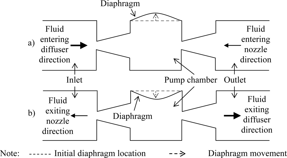
Generally, valveless diffuser micropumps are driven by a piezoelectric element bonded to a flexible diaphragm with no additional moving parts. Application of voltage on the piezoelectric element induces deformation on the diaphragm which creates displacement in the vertical direction (
Figure 1) and generates pressure head inside the pump chamber. The ability of the micropump to direct the working fluid inside the chamber is based upon the flow resistance in the diffuser elements.
The working principle of the diffuser elements in a valveless micropump is schematically shown in
Figure 1. In the “suction mode”, the diaphragm moves vertically upwards increasing the chamber volume and causes reduction in the chamber pressure. Pressure difference between the pump chamber and inlet/outlet enables the working fluid to be sucked into the pump chamber from both the inlet and outlet. At this instance, fluid will enter the pump chamber from the inlet through the diffuser direction while at the outlet, fluid will enter through the diffuser element at the nozzle direction instead. For the “pumping mode”, the reverse phenomenon occurs. The rate of fluid flow entering/exiting the chamber from/to the inlet and outlet is dependent on the design of the diffuser element where the effectiveness of the flow rectification of the micropump can be gauged upon the net flow of the fluid from the inlet to the outlet (which is the desired flow direction) during pumping. Hence optimization for the design of the diffuser element is of extreme importance in order to develop micropumps capable of operating at maximum efficiency.
Investigation on the effects of the diffuser element on the performance of valveless micropumps have been analyzed previously by simulating the diffuser model either by using commercially available numerical simulation software [
12] or through analytical works [
13–
20]. However, none of these analyses focused on the design optimization of the diffuser element to generate micropump with the maximum net flow rate considering the working conditions or the required specifications of the micropump.
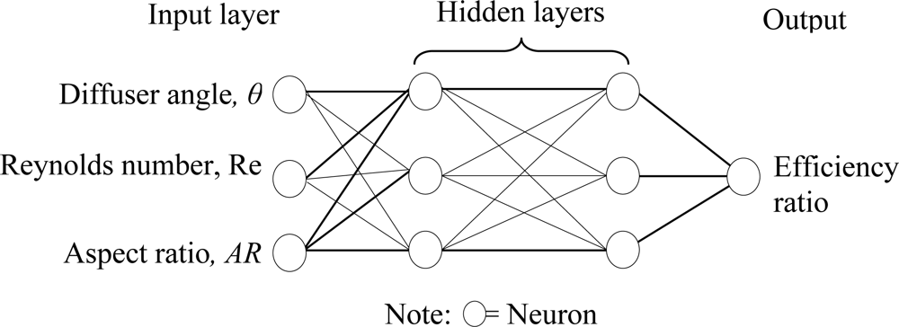
The purpose of this paper will be to present a neuro-genetic methodology to simulate and optimize the performance of the diffuser elements for applications in valveless diaphragm micropumps. The optimization methodology begins by simulating the diffuser model using commercially available numerical simulation software package, CoventorWare® to study the performance of the diffuser element under different working conditions and geometrical parameters. The simulation results obtained will be utilized for training the artificial neural networks (ANN) model.
An artificial neural network (ANN) is based on the working process of human brain in decision making. It is categorized as an artificial intelligence method and has been applied in many different fields such as control [
21], finance, aerospace, industrial and manufacturing [
22,
23]. The typical neural network consists of sets of inputs, sets of outputs and weighting functions. By knowing the input values, the output can be predicted. In other words, the network is defined to correlate between input and output by training the network with available data, such as results from numerical simulations. Once trained, the network can then be fed with any unknown input and is expected to predict the output (in this work, the diffuser efficiency ratio) with a high level of accuracy.
In order to perform optimization, direct associations between ANN and the optimization tool is required. Genetic algorithm (GA), which is also categorized as an artificial intelligence method, offers compatibility with ANN since GA would be able to find the global optimum in the local parametric search space provided by ANN. In view of that, the trained ANN is embedded as a fitness function into GA where the combined artificial neural network-genetic algorithm; hence the term “neuro-genetic”; will be used in sequence as a tool for search and optimization purposes. GA was the desired optimization techniques as both ANN and GA can be easily modeled and integrated in Matlab® since toolbox for both of these techniques is available as standard. Generally, GA is a robust adaptive search method based on Darwinian principles of natural selection, survival of the fittest and natural genetics. It combines survival of the fittest among string structures with a structured yet randomized information exchange to form a search algorithm with some of the innovative flair of human search [
24]. GA has been widely used for optimization purposes in microelectronic problems as shown in previous works by Man
et al. [
25], Arunasalam
et al. [
26] and Jeevan
et al. [
27], while a more detailed description of GA can be found texts written by Goldberg [
24], Mitchell [
28] and Houck
et al. [
29].
In this work, the purpose of the neuro-genetic optimization was to find the maximum efficiency ratio of diffuser element based on the diffuser angle, Reynolds number and aspect ratio under the specified working conditions and geometrical parameters of the micropump.
3. Results and Discussion
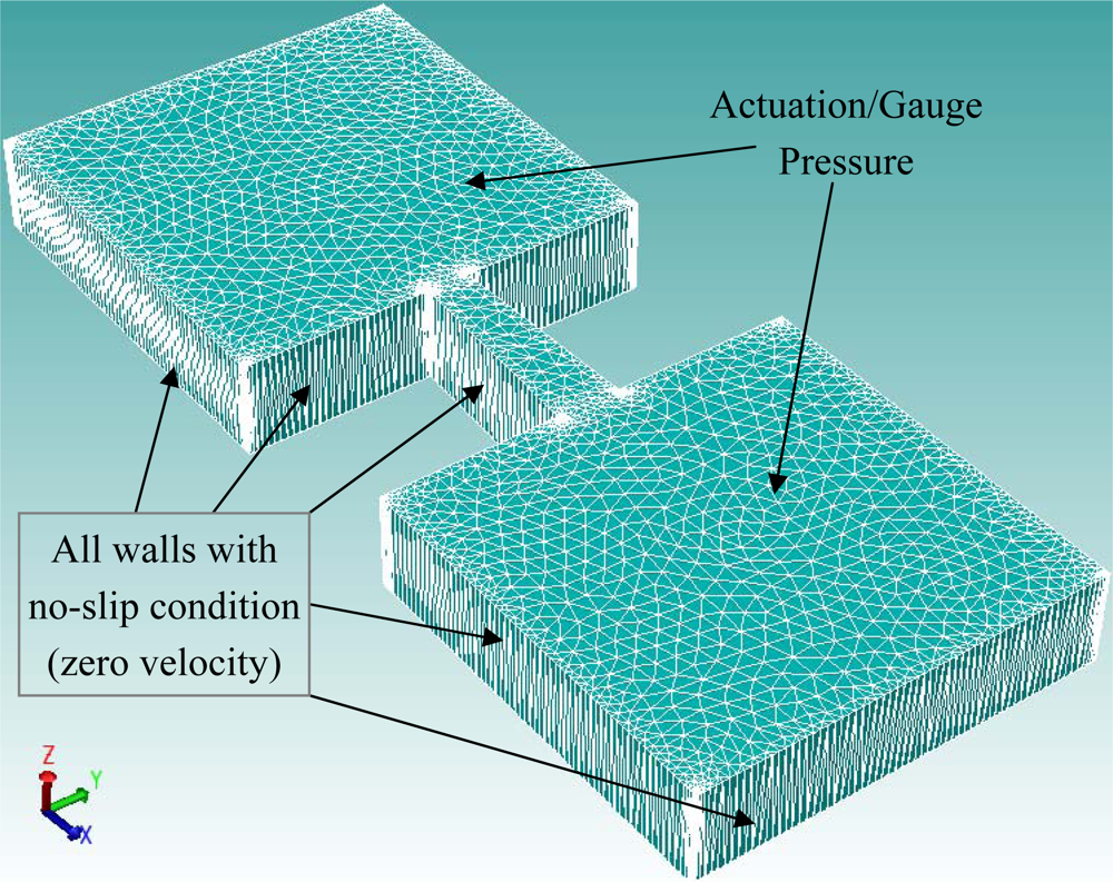
Numerical simulations for both the positive and negative direction of flow for the diffuser element have been conducted using the range of parameters given earlier in
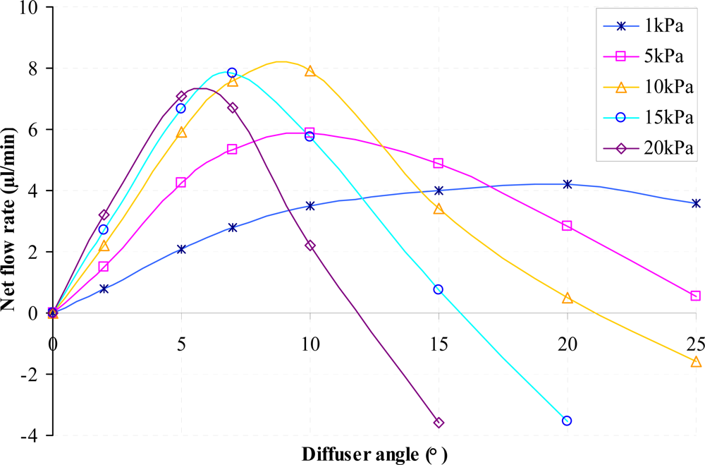
Table 1. Results of the volumetric net flow rate at the throat of the diffuser element obtained from CoventorWare® simulations for different diffuser angle is presented in
Figure 6 while
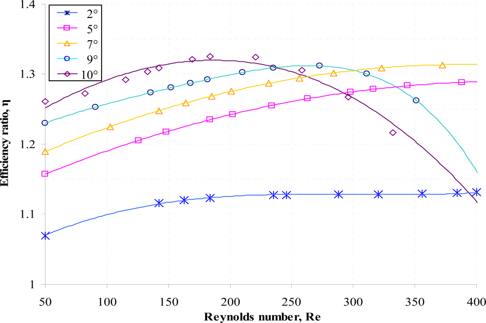
Figure 7 and
Figure 8 shows the efficiency ratio of the diffuser element for variations in Reynolds number and aspect ratio.
The net flow rate shows the effective fluid volume flowing through the diffuser element in the desired direction (positive direction). From
Figure 6 it can be seen that for the respective actuation pressure, an increase of the diffuser angle causes the net flow rate of the diffuser element to increase until reaching a maximum value. Any subsequent increase of the diffuser angle after the maximum net flow rate is reached will results in reduction of the net flow rate until the state where the net flow rate will become zero. At this instance, any further increment of the diffuser angle will instead create backflow where the net flow rate will be from the negative direction. It is apparent that there is an instance where the optimized net flow rate could be achieved at a specific diffuser angle. For cases where the net flow rate is negative, the volumetric flow rate is higher in the nozzle direction as compared to the diffuser direction due to the higher pressure loss coefficient in the diffuser direction. At this stage, net amount of fluid will be instead sucked into the supply chamber each pumping cycle.
Similar characteristics can be observed for variations in Reynolds number where there exists an optimized maximum efficiency ratio for a given diffuser angle as shown in
Figure 7. At higher Re, reduction in the efficiency ratio is imminent as flow separation; the phenomenon where some parts of the flow are actually going in a direction opposite to the bulk flow direction; is higher through the diffuser direction. This is due to the fact that at higher Re, the free stream flow velocity will be higher and will consequently be reduced in a rapid manner due to effect of the adverse pressure gradient present in the diffuser element. The sudden reduction of the free stream flow velocity resulted in the boundary layer unable to be sustained without separating from the wall. At this instance, flow separation will occur where another region of flow, in the opposite direction to the bulk flow direction, will be created near the wall. Meanwhile, pressure gradient inherent at the nozzle direction decreases with the flow direction due to the increasing free stream flow velocity. Hence at increasing Reynolds number, flow separation; which directly contributes to the pressure loss coefficient; increases more rapidly in the diffuser direction as compared to the nozzle direction. It is also apparent that reduction in the efficiency ratio for high Re is more significant at higher diffuser angle since expansion of the diffuser angle promotes more flow separation due to the sudden increase of the flow area which results in the reduction of the free stream flow velocity and consequently increases the adverse pressure gradient. In view of this, the overall pressure loss coefficient of the flow along the diffuser element will be dominated by the occurrence of the flow separation at higher diffuser angle.
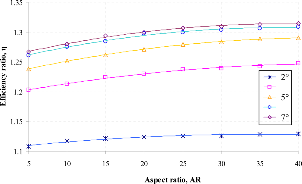
The effect of the diffuser element aspect ratio on the efficiency ratio is given in
Figure 8. As can be observed in the figure, there is a relatively small influence of the diffuser element aspect ratio on the efficiency ratio although generally the efficiency ratio increases when higher aspect ratio of the diffuser element is used. This is due to the fact that as the length increases, a small change of velocity in the diffuser element will be encountered resulting in a small amount of additional pressure recovery for flow through the diffuser direction. Hence a lower pressure loss coefficient at the diffuser direction,
ξd will be generated for the diffuser element. These findings concur well with the experimental results presented by Olsson
et al. [
10,
11].
Following results obtained, it can be ascertained that there are distinctive features for the influence of each parameters (diffuser angle, Reynolds number and aspect ratio) on the efficiency ratio of the diffuser element. Since mathematical modeling relating the efficiency ratio to θ, Re and AR is unknown, optimization could only be achieved by utilizing artificial intelligence tool which is capable of correlating the design parameters to the efficiency ratio with ease. For that purpose, the neuro-genetic optimization method has been performed to find the maximum efficiency ratio for the diffuser element under the range of parameters investigated.
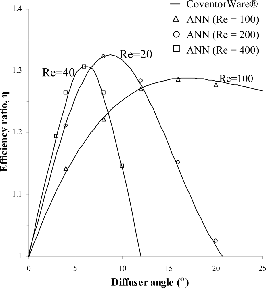
In order to assess the accuracy of the ANN predictions, validation has been made by comparing results for the efficiency ratio of the untrained numerical simulations with the ANN predictions.
Figure 9 shows comparison of the CoventorWare® simulations results with ANN predictions for the efficiency ratio obtained from variations of the diffuser angle at different Reynolds number. Additional comparison of results between CoventorWare® simulations and ANN predictions are presented in
Table 6. As mentioned earlier, five sets of data from each category of parameters from the numerical simulations that were not used for training in ANN will be presented for comparison purpose. From the results of
Figure 9 and
Table 6, it can be ascertain that the trained ANN was able to predict accurately the efficiency ratio of the diffuser element for the range of design parameters investigated. The percentage of errors from the ANN predictions is less than 2% while negligible for some cases, establishing the ANN predictions superiority.
Once a well-trained ANN is found, it is then embedded as a fitness function into genetic algorithms (GA) for optimization purposes. The optimization analysis has been performed to find the maximum efficiency ratio from the range of parameters available for selection in the trained ANN.
Figure 10 shows an example of utilizing GA to find the maximum efficiency ratio for variations in diffuser angle at fixed Reynolds number of 100, 200 and 400. The maximum efficiency ratios obtained along with the corresponding diffuser angle for each Reynolds number are shown in
Table 7 where it should be noted that only integers are used for parameters associated with the diffuser angle.
For the range of parameters indicated earlier in
Table 1 that have been considered for simulations in CoventorWare® and used for training the ANN, the maximum efficiency ratio attainable is 1.38 as optimized by the neuro-genetic methodology. The optimized maximum efficiency ratio achieved is the highest obtained thus far when compared against results from the overall parametric studies. This is due to the fact that the neuro-genetic optimization will be able to take into account all the possible combinations of parameters to generate the predicted output which are then compared until the highest efficiency ratio is found. However, it should be made clear that the highest efficiency ratio produced is only valid for application of the diffuser element within the range of parameters investigated. Another point to note is that in actual application, the range of Reynolds number varies according to flow condition. Hence the expected range of Reynolds number for the flow in the diffuser element should be estimated in advance so that the optimized parameters can be chosen based on the perceived application.
Table 8 shows parameters associated with the maximum efficiency ratio obtained while
Table 9 shows the five highest efficiency ratios generated by the neuro-genetic optimization along with the corresponding parameters. Results from the present study clearly indicate that a well trained ANN combined with GA can be used to optimize the efficiency ratio of the diffuser element with confidence. The neuro-genetic optimization methodology is able to predict the maximum efficiency ratio for the range of parameters under consideration without requiring the actual mathematical model governing the behavior of the fluid flow across the diffuser element to be defined. Additionally parametric studies can be conducted with ease through ANN simulations using only few numerical simulation results as the training inputs, eliminating the needs for extensive remodeling of the numerical model.


