Heat Transfer Measurements with Surface Mounted Foil-Sensors in an Active Mode: A Comprehensive Review and a New Design

Abstract
:1. Introduction
- films are very thin metal layers. They are so thin (typically 10 – 300 nm) that their physical properties and especially their temperature coefficient of electrical resistance, α, deviate from the corresponding bulk values [22,27]. Thin film sensors typically are manufactured by a sputtering technique (metal deposition on a substrate) [1,22].
- foils are thin metal layers typically of thickness ≤ 2 μm. They are thick enough for their physical properties to be the same as those of the corresponding bulk material. Thin foil sensors can be made from sheets of metal foils, glued to a carrier foil and cut or etched in its final shape. This is our new “laminating and etching technology” described in Chapter 4.
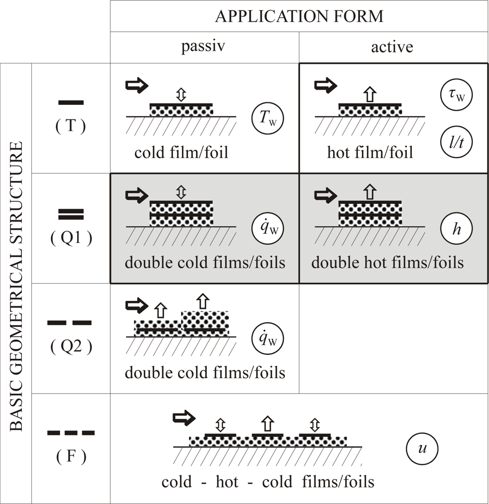
2. Characterization Scheme for RTS Film- and Foil-Sensors
- ❒ Their basic geometrical structure, determined by the quantity to be measured, which can be
- wall temperature TW
- wall heat flux density q̇W
- wall shear stress τW
- location of laminar/turbulent transition (l/t)
- flow velocity, individually defined (u)
- ❒ Their application form on the wall, determined by the mode of measurement, which can be
- a passive mode (negligible self heating)
- an active mode (strong self heating)
- T: one single film/foil for temperature measurement
- Q1: two single films/foils, one upon the other, for heat flux measurements
- Q2: two single films/foils, side by side, for heat flux measurements
- F: two or more single films/foils, side by side, for flow measurements
- Accurate measurements require high values of sensitivity SR. The coefficient α is given by the sensitive material, influenced by the manufacturing technology of the SE due to different film or foil thicknesses. The resistance R0 is given by its material characteristic value ρe and by its geometrical dimensions. According to (4) and (5) high values of resistance R are advantegeous to achieve high sensor signals U with low uncertainties ΔU.
- Local measurements require small sensor areas ASE, i.e. small l and b for three dimensional and small b for two dimensional cases. Characteristic length scales of the phenomena under consideration may vary over a wide range or even orders of magnitude. The geometric sensor dimensions must match these scales. In order to get high values of resistance, however, the sensor should be as large as possible.
- Time resolved measurements require small response times. These time constants are characteristic not only of the TSE but also of the complete sensor on the body under observation. A complete sensor consists of one or more SE, the substrate or carrier on which the SE are mounted, glued or deposited and a casing if requiered. In order to get small response times the sensor should be as small as possible, especially with respect to its heat capacity. The SE should be in good thermal contact with the object under consideration. In the case of wall temperature measurement ((T) passive in Figure 1) a good thermal contact to the body must be guaranteed. For wall shear stress measuremens with a hot-film ((T) active in Figure 1) a good thermal contact to the fluid and a good thermal insulation against the body are requiered.
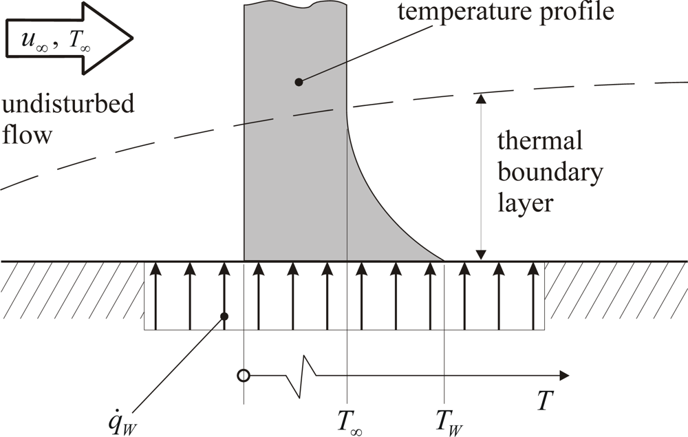
3. The Heat Transfer Sensor Concept
- the local heat flux density, q̇W
- the local wall temperature, TW
- the ambient temperature, T∞
4. Sensor Design and Manufacturing
4.1. Design Considerations
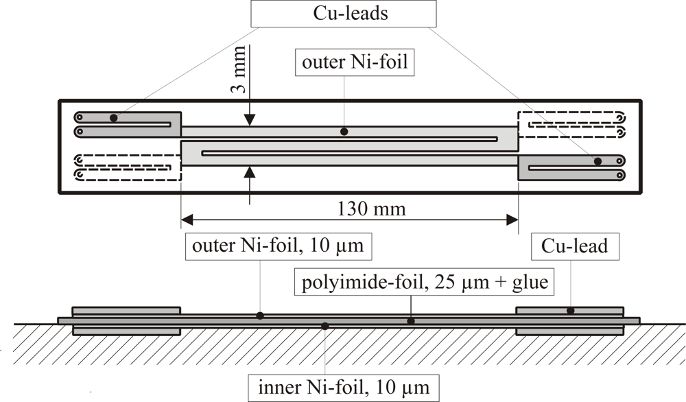
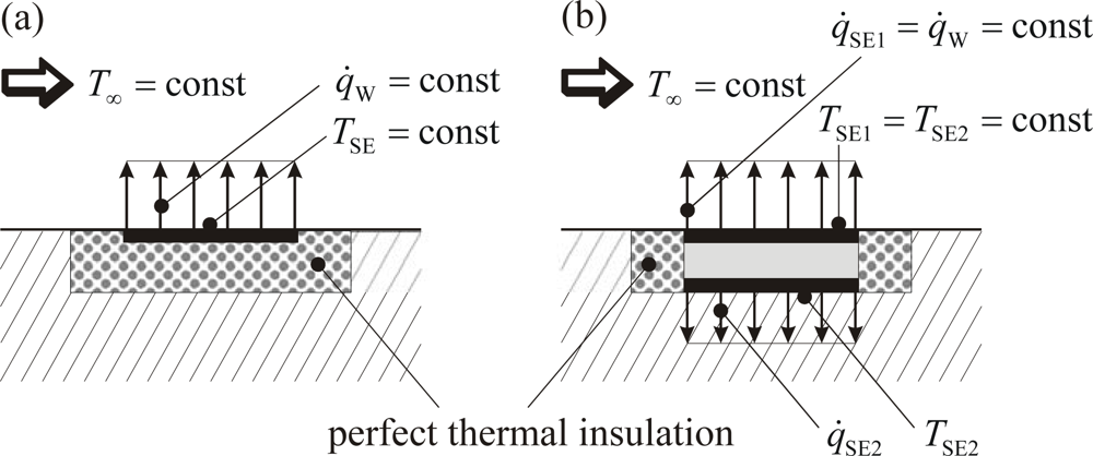
- The size of the sensor is a compromise between “as small as possible for local measurements” and “as large as possible for low measurement uncertainties”. In our case this compromise was b = 3 mm in streamwise direction for the simple prototype according to Figure 4. Here two foils are arranged, one exactly above the other, with a thin polyimide-foil between. The design of the more advanced sensor is shown in Figure 5 and Figure 6 below.
- There should be a good contact between the sensor and the surface and only negligible interference with the flow. When sensors are flush mounted interference can be avoided completely. That, however, requires a surface intrusion and poses additional problems due to the increased heat conduction into the wall material. As an alternative, sensors should be glued to the surface. To avoid inacceptably strong interference with the flow its wall normal extend should be below n+ ≈ 30, with n+ being the turbulent wall coordinate (n+ = uτn/v; : shear stress velocity; τW: wall shear stress; ρ: fluid density; ν: kinematic viscosity [28]). In our cases an overall sensor thickness of H ≈ 200 μm corresponds to H+ = uτH/v ≈ 3 at Re = 26,000.
- The material of the sensor foils should be characterized by a large temperature coefficient α according to equation (2). This is achieved with nickel (foils). They are well protected by an inert oxid layer. This, however, may pose problems with respect to glueing, etching and (electrically) contacting the foils.
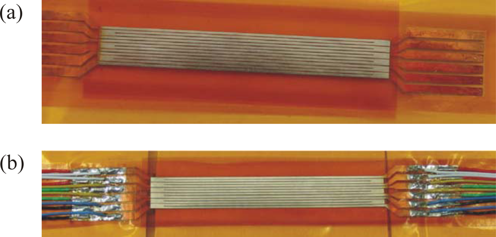
4.2. Manufacturing Details
- In a vacuum process (p < 10−2 Pa) the Ni-foils are heated until red-hot by an electrical current (25A for the 10 μm foil) for about 2 minutes. This reduces the surface oxide layer to a level that allows a subsequent copper vapour deposition of those (end) parts of the foils that will carry the electrical contacts. This is achieved by a mask that clears the area to be coated.
- The partly copper-coated foils then are glued on two separate 25 μm carrier foils (polyimide) with a 25 μm glue layer (epoxy- resin) on one side.
- Like an electrical printed circuit board is etched after a photo mask of the final metal surface is applied, the Ni-foils now take their final shape by etching away their superfluous parts. Special attention must be given to the facts that
- the carrier/Ni-foil combination is highly flexible
- adhesion of the photo resist layer is weak
- the etching behaviour on copper is different from that on nickel
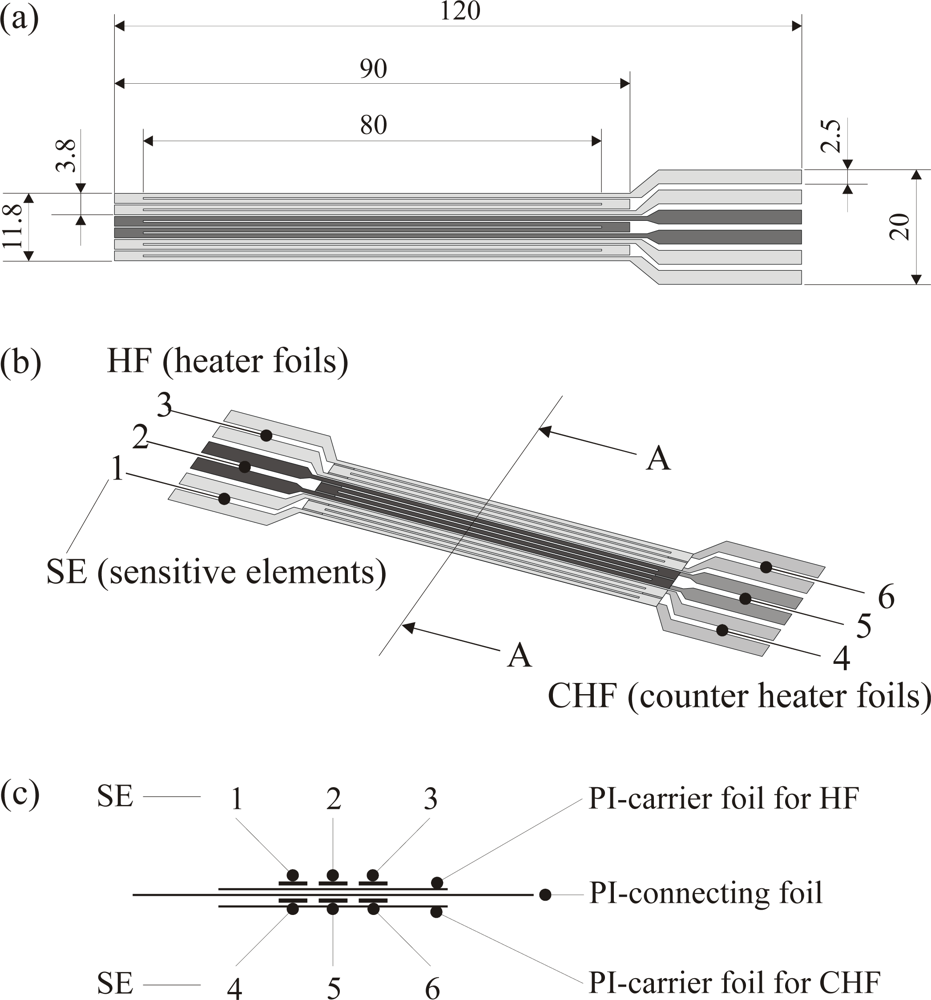
- Both carrier/Ni-foil combinations are glued together by a connecting foil (polyimide with glue layers on both sides) one on top of the other. The upper one now serves as heating foil, the lower one as counter-heating foil.
- After joining the electrical contacts by soldering them to the copper coated end parts of the Ni-foils the sensor is ready for calibration in a temperature controlled calibration chamber.
5. Test Case and Calibration Procedures
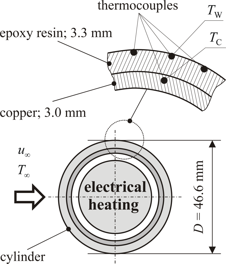
5.1. Test Case: Circular Cylinder in Cross Flow
- (13LT) for Re = 13,000 and low turbulence
- (13HT) for Re = 13,000 and high turbulence
- (26LT) for Re = 26,000 and low turbulence
- (26HT) for Re = 26,000 and high turbulence
5.2. Calibration Procedures
- C1: Calibration of the sensor itself. Results are technical data of the sensor.
- C2: Calibration with respect to systematic errors introduced by implementation of the sensor in the situation under consideration.
- C3: Calibration with respect to the final physical quantity which may differ from the one that is measured directly. The targeted quantity then follows through an equivalence relation.
5.2.1. Step C1: Calibration of the Sensor Itself
5.2.2. Step C2: Calibration with Respect to Systematic Errors
5.2.3. Step C3: Calibration with Respect to an Equivalence Relation
6. Test Measurements, Results
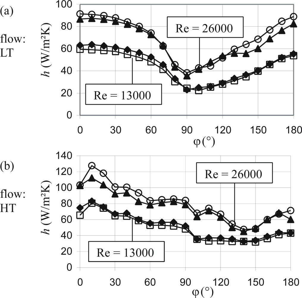
6.1. Heat Transfer Coefficient around a Circular Cylinder (Simple Sensor)
6.2. Heat Transfer Coefficient around a Circular Cylinder (Advanced Sensor)
6.3. Double Foil Sensors in Passive Mode
7. Error Analysis
8. Conclusions
Nomenclature
| A | thermal adjustment coefficient (-) |
| A | area (mm2) |
| b | width (mm) |
| C | coefficient (-) |
| D | diameter (mm) |
| d | diameter, thickness (mm) |
| H | sensor thickness (μm) |
| h, ĥ | heat transfer coefficient (W/m2K) |
| k | thermal conductivity (W/mK) |
| L | characteristic length of a heat transferring sensor or body (mm) |
| l | length (mm) |
| n | wall coordinate (μm) |
| n+ | turbulent wall coordinate (-) |
| Nu | Nusselt number (-) |
| P | electrical power (mW) |
| p | pressure (Pa) |
| q̇ | heat flux density (W/m2) |
| R | electrical resistance (Ω) |
| Re | Reynolds number (-) |
| S | sensitivity of the TSE (Ω/K) |
| T | temperature (°C) |
| U | voltage (V) |
| u | fluid velocity (m/s) |
| uτ | shear stress velocity (m/s) |
| Greek symbols | |
|---|---|
| α | temperature coefficient of electrical resistance (1/K) |
| φ | angle-position of the sensor, glued on the circular cylinder (°) |
| ν | kinematic viscosity (m2/s) |
| ρ | fluid density (kg/m3) |
| ρe | electrical resistivity (Ωm) |
| τW | wall shear stress (N/m2) |
| Subscripts | |
|---|---|
| 0 | baseline |
| ∞ | undisturbed fluid |
| b | body |
| c | cross section |
| C | copper tube |
| cg | carrier and glue |
| cs | complete sensor |
| e | electrical |
| E | epoxy resin |
| eff | effective |
| f | fluid |
| l | lower surface |
| m | measure |
| r | reference |
| R | resistance |
| SE | sensitive element |
| V | placed in series |
| W | wall |
| Abbreviations | |
|---|---|
| CHF | counter heater foil |
| DFS | double foil sensor |
| HE | heating element |
| HF | heater foil |
| HT | high turbulence |
| LT | low turbulence |
| MEMS | microelectromechanical system |
| PCB | printed circuit board |
| PI | polyimide |
| RTS | resistance temperature sensor |
| SE | sensitive element |
| TSE | temperature sensitive element |
| TFTS | thin foil triple sensor |
Acknowledgments
References
- Lichtenwalner, D.J.; Hydrick, A.E.; Kingon, A.I. Flexible thin film temperature and strain sensor array utilizing a novel sensing concept. Sens. Actuat. A 2007, 135, 593–597. [Google Scholar]
- Thorpe, S.J.; Yoshino, S.; Ainsworth, R.W.; Harvey, N.W. An investigation of the heat transfer and static pressure on the over-tip casing of an axial turbine operating at engine representative flow conditions. (I). Time-mean results. Int. J. Heat Fluid Flow 2004, 25, 933–944. [Google Scholar]
- Thorpe, S.J.; Yoshino, S.; Ainsworth, R.W.; Harvey, N.W. An investigation of the heat transfer and static pressure on the over-tip casing of an axial turbine operating at engine representative flow conditions. (II). Time-resolved results. Int. J. Heat Fluid Flow 2004, 25, 945–960. [Google Scholar]
- Piccini, E.; Guo, S.M.; Jones, T.V. The development of a new direct-heat-flux gauge for heat-transfer facilities. Meas. Sci. Technol 2000, 11, 342–349. [Google Scholar]
- Hogendoorn, C.J.; de Lange, H.C.; van Steenhoven, A.A. Design optimization for fast heat-transfer gauges. Meas. Sci. Technol 1998, 9, 428–434. [Google Scholar]
- Epstein, A.H.; Guenette, G.R.; Norton, R.J.G.; Yuzhang, C. High-frequency response heat-flux gauge. Rev. Sci. Instrum 1986, 57, 639–649. [Google Scholar]
- Fralick, G.; Wrbanek, J.; Blaha, C. Thin film heat flux sensor of improved design. Proceedings of NASA Technical Memorandum; NASA: Washington, USA, 2002. NASA/TM-2002-211566. pp. 1–14. [Google Scholar]
- Mocikat, H.; Herwig, H. An advanced thin foil sensor concept for heat flux and heat transfer measurements in fully turbulent flows. Heat Mass Transfer 2007, 43, 351–364. [Google Scholar]
- Stefanescu, S.; DeAnna, R.G.; Mehregany, M. Experimental performance of a micromachined heat flux sensor. Proceedings of NASA Technical Memorandum; NASA: Washington, USA, 1998. NASA/TM-1998-107517. pp. 1–16. [Google Scholar]
- Haselbach, F.; Nitsche, W. Calibration of single-surface hot films and in-line hot-film arrays in laminar or turbulent flows. Meas. Sci. Technol 1996, 7, 1428–1438. [Google Scholar]
- Naughton, J.W.; Sheplak, M. Modern developments in shear-stress measurement. Progr. Aerospace Sci 2002, 38, 515–570. [Google Scholar]
- Desgeorges, O.; Lee, T.; Kafyeke, F. Multiple hot-film sensor array calibration and skin friction measurement. Exp. Fluid 2002, 32, 37–43. [Google Scholar]
- Kim, I.C.; Lee, S.J. Characterization of a miniature thermal shear-stress sensor with backside connections. Sens. Actuat. A 2006, 128, 305–311. [Google Scholar]
- Löfdahl, L.; Gad-el-Hak, M. MEMS-based pressure and shear stress sensors for turbulent flows. Meas. Sci. Technol 1999, 10, 665–686. [Google Scholar]
- Liu, C.; Huang, J.B.; Zhu, A.Z.; Jiang, F.; Tung, S.; Tai, Y.C.; Ho, C.M. A micromachined flow shear stress sensor based on thermal transfer principles. J. Micro. Elec. Mech. Sys 1999, 8, 90–99. [Google Scholar]
- Xu, Y.; Chiu, C.W.; Jiang, F.; Lin, Q.; Tai, Y.C. A MEMS multe-sensor chip for gas flow sensing. Sens. Actuat. A 2005, 121, 253–261. [Google Scholar]
- Chandrasekaran, V.; Cain, A.; Nishida, T.; Cattafesta, L.N.; Sheplak, M. Dynamic calibration technique for thermal shear-stress sensors with mean flow. Exp. Fluid 2005, 39, 56–65. [Google Scholar]
- Lee, T.; Basu, S. Measurement of unsteady boundary layer developed on an oscillating airfoil using multiple hot-film sensors. Exp. Fluid 1998, 25, 108–117. [Google Scholar]
- Jiang, F.; Lee, G.B.; Tai, Y.C.; Ho, C.M. A flexible micromachine-based shear-stress sensor array and its application to separation-point detection. Sens. Actuat 2000, 79, 194–203. [Google Scholar]
- Xu, Y.; Jiang, F.; Newbern, S.; Huang, A.; Ho, C.M.; Tai, Y.C. Flexible shear-stress sensor skin and its application to unmanned aerial vehicles. Sens. Actuat. A 2003, 105, 321–329. [Google Scholar]
- Nguyen, N.T.; Huang, X.Y.; Toh, K.C. Thermal flow sensor for ultra-low velocities based on printed circuit board technology. Meas. Sci. Technol 2001, 12, 2131–2136. [Google Scholar]
- Mailly, F.; Giani, A.; Bonnot, R.; Temple-Boyer, P.; Pascal-Delannoy, F.; Foucaran, A.; Boyer, A. Anemometer with hot platinum thin film. Sens. Actuat. A 2001, 94, 32–38. [Google Scholar]
- Shin, W.C.; Besser, R.S. A micromachined thin-film gas flow sensor for microchemical reactors. J. Micromech. Microeng 2006, 16, 731–741. [Google Scholar]
- Kim, S.; Nam, T.; Park, S. Measurement of flow direction and velocity using a micromachined flow sensor. Sens. Actuat. A 2004, 114, 312–318. [Google Scholar]
- Sabaté, N.; Santander, J.; Fonseca, L.; Gràcia, I.; Cané, C. Multi-range silicon micromachined flow sensor. Sens. Actuat. A 2004, 110, 282–288. [Google Scholar]
- Fürjes, P.; Légrádi, G.; Dücsó, C.; Aszódi, A.; Bársony, I. Thermal characterisation of a direction dependent flow sensor. Sens. Actuat. A 2004, 115, 417–423. [Google Scholar]
- Weiping, Y.; Henan, L.; Junshan, L.; Jihong, G. EPMA and XRD study on nickel metal thin film for temperature sensor. Sens. Actuat. A 2007, 136, 212–215. [Google Scholar]
- Herwig, H. Strömungsmechanik. Springer-Verlag: Berlin Heidelberg, Germany, 2002; pp. 219–248. [Google Scholar]
- Mocikat, H.; Herwig, H. Heat transfer measurements in fully turbulent flows: basic investigations with an advanced thin foil triple sensor. Heat Mass Transfer 2008, 44, 1107–1116. [Google Scholar]
 : metal film/foil;
 : solation,thermal barrier (e.g., polyimide foil);
 : flow direction;
 : heat flux directions;
 : targeted quantity, x = TW, τW, …
: metal film/foil;
: solation,thermal barrier (e.g., polyimide foil);
: flow direction;
: heat flux directions;
: targeted quantity, x = TW, τW, …
: targeted quantity, x = TW, τW, …
: metal film/foil;
: solation,thermal barrier (e.g., polyimide foil);
: flow direction;
: heat flux directions;
: targeted quantity, x = TW, τW, …


 : no heating upstream;
 : one heating foil active upstream;
 : two heating foils active upstream.
: no heating upstream;
: one heating foil active upstream;
: two heating foils active upstream.
: two heating foils active upstream.
: no heating upstream;
: one heating foil active upstream;
: two heating foils active upstream.


| Electrical sensor data | Thermal sensor data | ||||
|---|---|---|---|---|---|
| TFTS SE | RSE0 [Ω] | αRSE0 [mΩ/K] | α [10−3/K] | DFS | (k / d) [W/m2K] |
| 1 | 16.31 | 78.49 | 4.81 | 1 ÷ 4 | 800 |
| 2 | 16.18 | 77.96 | 4.82 | ||
| 3 | 16.08 | 77.64 | 4.83 | 2 ÷ 5 | 705 |
| 4 | 15.34 | 77.02 | 5.02 | ||
| 5 | 15.42 | 78.16 | 5.07 | 3 ÷ 6 | 705 |
| 6 | 15.43 | 77.94 | 5.05 | ||
© 2009 by the authors; licensee MDPI, Basel, Switzerland This article is an open access article distributed under the terms and conditions of the Creative Commons Attribution license (http://creativecommons.org/licenses/by/3.0/).
Share and Cite
Mocikat, H.; Herwig, H. Heat Transfer Measurements with Surface Mounted Foil-Sensors in an Active Mode: A Comprehensive Review and a New Design. Sensors 2009, 9, 3011-3032. https://doi.org/10.3390/s90403011
Mocikat H, Herwig H. Heat Transfer Measurements with Surface Mounted Foil-Sensors in an Active Mode: A Comprehensive Review and a New Design. Sensors. 2009; 9(4):3011-3032. https://doi.org/10.3390/s90403011
Chicago/Turabian StyleMocikat, Horst, and Heinz Herwig. 2009. "Heat Transfer Measurements with Surface Mounted Foil-Sensors in an Active Mode: A Comprehensive Review and a New Design" Sensors 9, no. 4: 3011-3032. https://doi.org/10.3390/s90403011
APA StyleMocikat, H., & Herwig, H. (2009). Heat Transfer Measurements with Surface Mounted Foil-Sensors in an Active Mode: A Comprehensive Review and a New Design. Sensors, 9(4), 3011-3032. https://doi.org/10.3390/s90403011