A Fast Inspection of Tool Electrode and Drilling Depth in EDM Drilling by Detection Line Algorithm

Abstract
:1. Introduction
2. Materials and Methods
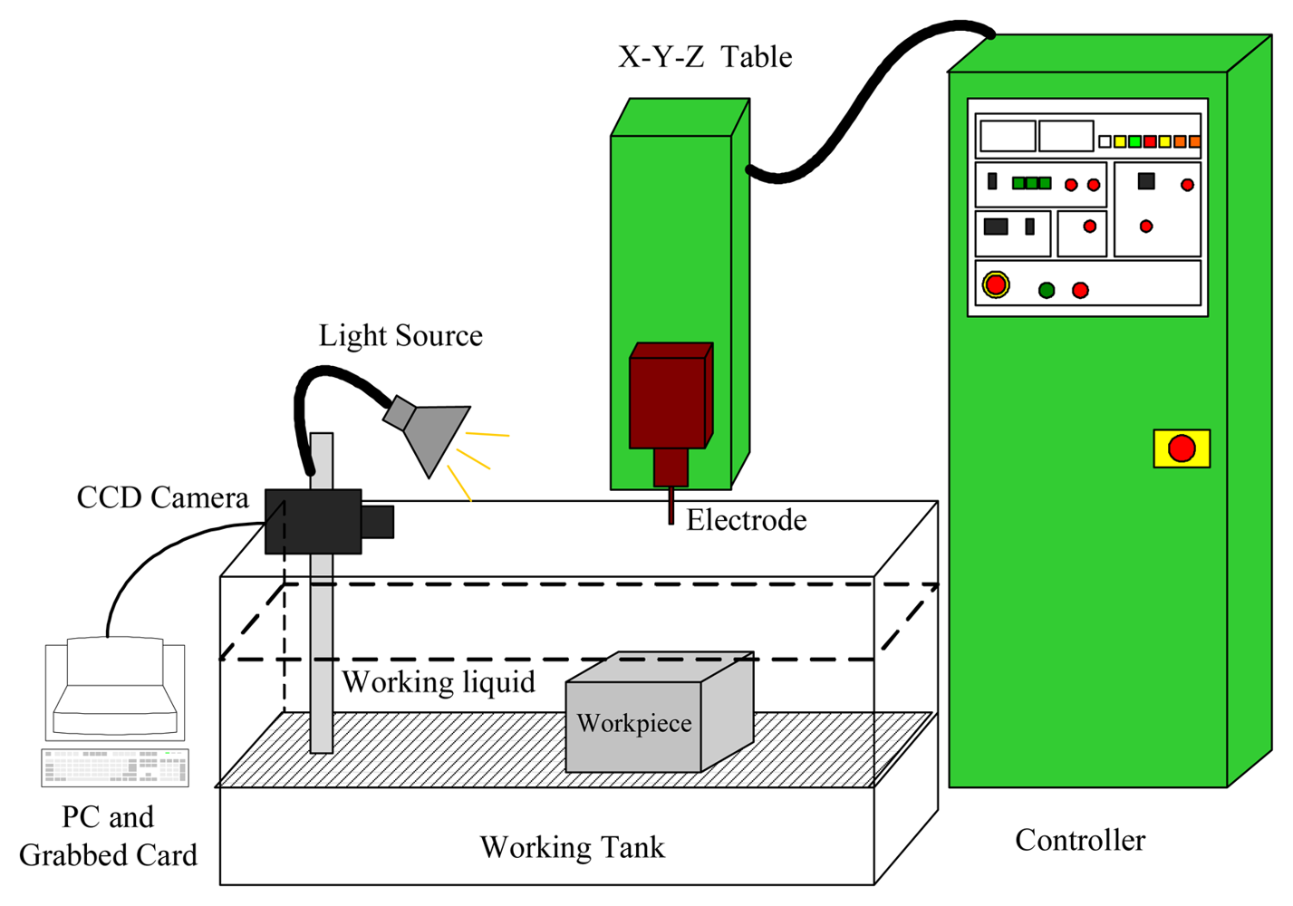
2.1 Image Acquisition System and EDM Drilling Machine
2.2 Electrode Length and Drilling Depth Detection
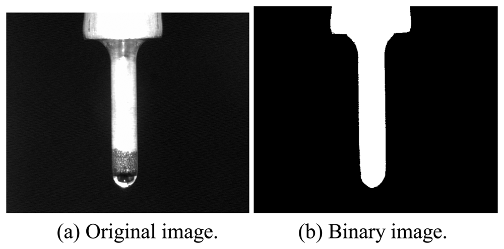
2.2.1 Electrode Image Extraction
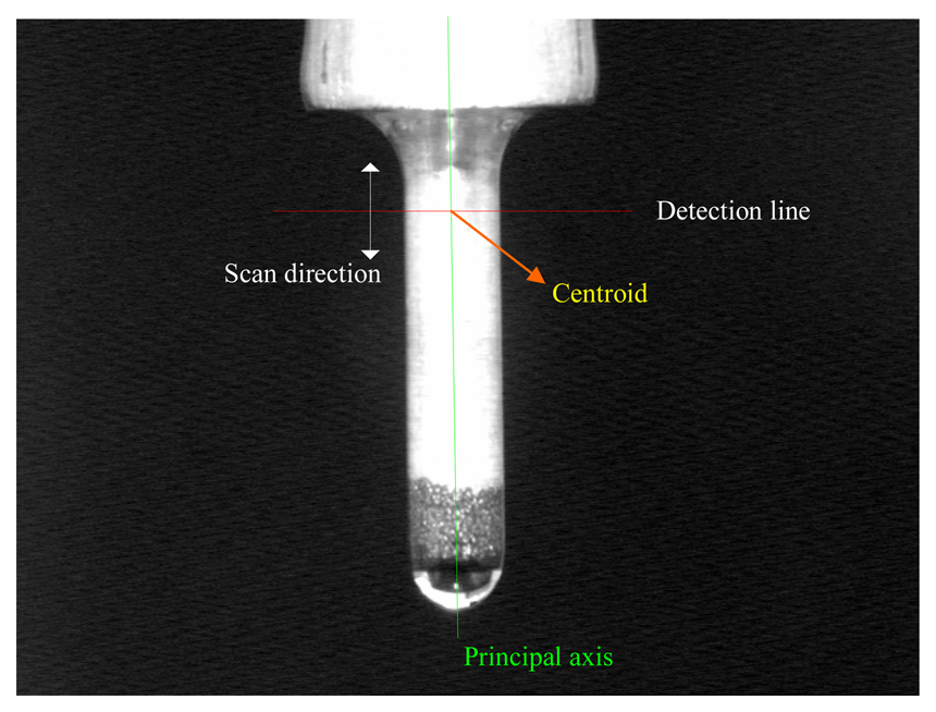
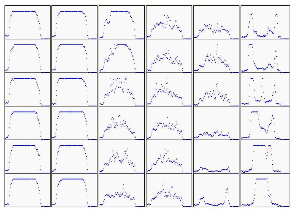
2.2.2 Detection Line Algorithm
- Step 1:
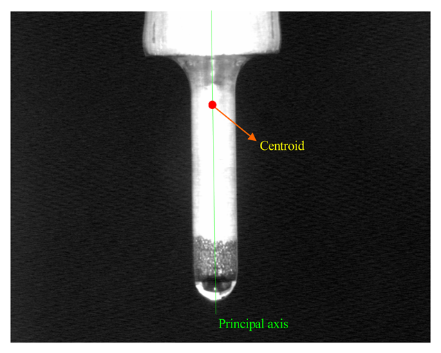
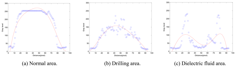
- Compute the distribution function of gray level defined asby a polynomial curve fitting method [11], where p = {p1, p2, …, pn} is a position parameter of the detection line along the principle axis of the tool electrode centroid and t is a distance variable with the detection line.
- Step 2:
- Find the local maximum value gmax(pi,t) according to g(pi,t). Further, the function of local maximize value gmax(p,t) is established by obtaining gmax(pi,t).
- Step 3:
- Determine the boundaries:
- (1)
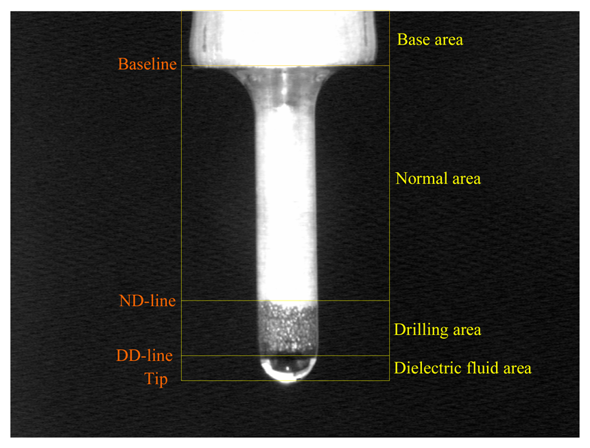
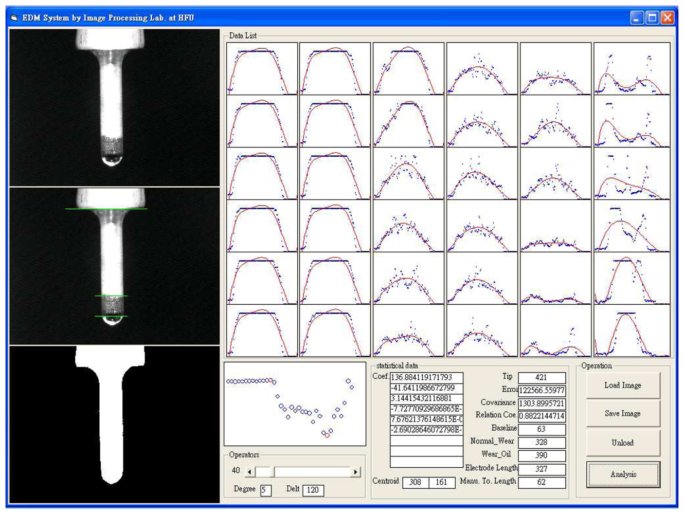
- BaselineThe diameter function of electrode d(p) is established by a detection line. The first-order derivatives of d(p) is defined asThus, the location of baseline is obtained at the point pmax as maximum value of |d′(p)|. It means that an obvious variation of the diameter is at the baseline.
- (2)
- ND-lineThe slope variation m(pi,t) of gmax (pi, t) is defined asTherefore, the position of ND-line can be found at point pND as the first obvious variation |m(pND,t)| ≥ δ on scanning the tool electrode. δ is a positive constant.
- (3)
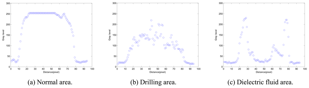
- DD-lineThe peak decision method (PD method) is based on the peak number (PN) of g(pi,t) moving along the tool electrode in this study. The location of DD-line is detected by PD method when PN is alternated from 1 (a single peak) to 2 (a dual peak). PN is defined as
- Step 4:
- The tool electrode length and drilling depth are defined as:
- (1)
- Tool electrode length is the distance between the baseline and ND-line.
- (2)
- Drilling depth is the distance between the ND-line and DD-line.
3. Results and Discussion
4. Conclusions
References and Notes
- Yu, Z.; Masuzawa, T.; Fujiino, M. Micro-EDM for three-dimensional cavities-development of uniform wear method. Ann. CIRP 1998, 47, 169–172. [Google Scholar]
- Tsai, Y.Y.; Masuzawa, T. An index to evaluate the wear resistance of the electrode in micro-EDM. Journal of Materials Processing Tech. 2004, 149, 304–309. [Google Scholar]
- Dauw, D. On the deviation and application of a real-time wear sensor in EDM. Ann. CIRP 1986, 35, 111–116. [Google Scholar]
- Bleys, P.; Kruth, J. -P.; Lauwers, B.; Zryd, A.; Delpretti, R.; Tricarico, C. Real-time tool wear compensation in milling EDM. Ann. CIRP 2002, 51, 157–160. [Google Scholar]
- Bleys, P.; Kruth, J. -P.; Lauwers, B. Sensing and compensation of tool wear in milling EDM. Journal of Materials Processing Technology 2004, 149, 139–146. [Google Scholar]
- Jurkovic, J.; Korosec, M; Kopac, J. New approach in tool wear measuring technique using CCD vision system. International Journal of Machine Tools and Manufacture 2005, 45, 1023–1030. [Google Scholar]
- Kim, J.H.; Moon, D.K.; Lee, D.W.; Kim, J.S.; Kang, M.C.; Kim, K.H. Tool wear measuring technique on the machine using CCD and exclusive jig. Journal of Materials Processing Technology 2002, 130, 668–674. [Google Scholar]
- Sortino, M. Application of statistical filtering for optical detection of tool wear. International Journal of Machine Tools and Manufacture 2003, 43, 493–497. [Google Scholar]
- Kwon, Y.; Fischer, G.W. A novel approach to quantifying tool wear and too life measurements for optimal tool management. International Journal of Machine Tools and Manufacture 2003, 43, 359–368. [Google Scholar]
- Kaneko, T.; Tsuchiya, M.; Kazama, A. Improvement of 3D NC contouring EDM using cylindrical electrodes and optical measurement of electrode deformation and machining of free-curves. Proceedings of 10th International Symposium for Electro Machining (ISEM-10) 1992, 364–367. [Google Scholar]
- Foley, J.D.; Dam, A.D.; Feiner, S.K.; Hughes, J.F. Computer graphics: principles and practice. Addison-Wesley 1997. [Google Scholar]


| Parameters | Values |
|---|---|
| Electrode material | Copper |
| Peak current | 5.0A, 6.0A |
| Open voltage | 90 V |
| Pulse duration | 100 μs |
| Pulse interval | 100 μs |
| Diameter of tool electrode | Ø 2.0, 2.5, 3.0 mm |
| Workpiece material | SKD11 |
| Gap distance | 0.05 mm |
| Dielectric flushing method | Static condition |
| Machined depth | 1.5, 2.0, 2.5, 3.0 mm |
| No. | Machining condition | Electrode diameter | Ave. machining time (min.) | Ave. electrode length (mm) | Ave. Machined depth (mm) | |||||
|---|---|---|---|---|---|---|---|---|---|---|
| Manual | Estimated | Error | Manual | Estimated | Error | |||||
| 1 | Setting depth | 2.0 mm | 1.5 mm | 42 | 19.85 | 19.76 | 0.09 | 2.08 | 1.95 | 0.13 |
| 2.0 mm | 61 | 19.96 | 19.89 | 0.07 | 2.08 | 1.97 | 0.11 | |||
| Peak current | 5.0 A | 2.5 mm | 117 | 19.93 | 19.94 | 0.01 | 2.12 | 1.96 | 0.16 | |
| 3.0 mm | 149 | 19.87 | 19.89 | 0.02 | 2.11 | 1.97 | 0.14 | |||
| 2 | Setting depth | 3.0 mm | 1.5 mm | 53 | 19.77 | 19.88 | 0.11 | 3.13 | 2.89 | 0.24 |
| 2.0 mm | 99 | 19.91 | 19.94 | 0.03 | 3.17 | 2.87 | v0.30 | |||
| Peak current | 5.0 A | 2.5 mm | 152 | 19.85 | 19.94 | 0.09 | 3.04 | 2.82 | 0.22 | |
| 3.0 mm | 199 | 19.91 | 20.04 | 0.13 | 3.14 | 2.87 | 0.27 | |||
| 3 | Setting depth | 4.0 mm | 1.5 mm | 60 | 19.78 | 19.92 | 0.14 | 4.19 | 3.85 | 0.34 |
| 2.0 mm | 114 | 19.91 | 19.94 | 0.03 | 4.10 | 3.89 | 0.21 | |||
| Peak current | 5.0 A | 2.5 mm | 163 | 19.78 | 19.84 | 0.06 | 4.21 | 3.81 | 0.40 | |
| 3.0 mm | 217 | 19.92 | 19.94 | 0.02 | 4.29 | 3.89 | 0.40 | |||
| 4 | Setting depth | 5.0 mm | 1.5 mm | 74 | 19.97 | 19.84 | 0.13 | 5.05 | 4.92 | 0.13 |
| 2.0 mm | 133 | 19.88 | 19.90 | 0.02 | 5.10 | 4.96 | 0.14 | |||
| Peak current | 5.0 A | 2.5 mm | 174 | 20.04 | 20.05 | 0.01 | 5.06 | 4.92 | 0.14 | |
| 3.0 mm | 242 | 20.03 | 19.94 | 0.09 | 5.08 | 4.97 | 0.11 | |||
| 5 | Setting depth | 2.0 mm | 1.5 mm | 28 | 19.92 | 19.94 | 0.02 | 2.14 | 1.88 | 0.26 |
| 2.0 mm | 41 | 19.83 | 19.99 | 0.16 | 2.12 | 1.90 | 0.22 | |||
| Peak current | 6.0 A | 2.5 mm | 72 | 19.95 | 19.89 | 0.06 | 2.13 | 1.86 | 0.27 | |
| 3.0 mm | 104 | 19.99 | 19.84 | 0.15 | 2.11 | 1.89 | 0.22 | |||
| 6 | Setting depth | 3.0 mm | 1.5 mm | 36 | 19.88 | 19.94 | 0.06 | 3.14 | 2.87 | 0.27 |
| 2.0 mm | 65 | 19.86 | 19.84 | 0.02 | 3.19 | 2.88 | 0.31 | |||
| Peak current | 6.0 A | 2.5 mm | 94 | 19.85 | 19.79 | 0.06 | 3.15 | 2.86 | 0.29 | |
| 3.0 mm | 134 | 19.84 | 19.89 | 0.05 | 3.22 | 2.90 | 0.32 | |||
| 7 | Setting depth | 4.0 mm | 1.5 mm | 54 | 19.87 | 19.89 | 0.02 | 4.17 | 3.84 | 0.33 |
| 2.0 mm | 79 | 19.78 | 19.89 | 0.11 | 4.16 | 3.88 | 0.28 | |||
| Peak current | 6.0 A | 2.5 mm | 115 | 19.87 | 19.79 | 0.08 | 4.18 | 3.91 | 0.27 | |
| 3.0 mm | 187 | 19.93 | 19.79 | 0.14 | 4.20 | 3.90 | 0.30 | |||
| 8 | Setting depth | 5.0 mm | 1.5 mm | 65 | 19.82 | 19.94 | 0.12 | 5.16 | 4.89 | 0.27 |
| 2.0 mm | 107 | 19.87 | 19.84 | 0.03 | 5.19 | 4.92 | 0.27 | |||
| Peak current | 6.0 A | 2.5 mm | 148 | 19.59 | 19.74 | 0.15 | 5.13 | 4.87 | 0.26 | |
| 3.0 mm | 213 | 19.73 | 19.84 | 0.11 | 5.15 | 4.90 | 0.25 | |||
| Ave. error | 0.075 | Ave. error | 0.245 | |||||||
© 2008 by the authors; licensee Molecular Diversity Preservation International, Basel, Switzerland. This article is an open access article distributed under the terms and conditions of the Creative Commons Attribution license ( http://creativecommons.org/licenses/by/3.0/).
Share and Cite
Huang, K.-Y. A Fast Inspection of Tool Electrode and Drilling Depth in EDM Drilling by Detection Line Algorithm. Sensors 2008, 8, 4866-4877. https://doi.org/10.3390/s8084866
Huang K-Y. A Fast Inspection of Tool Electrode and Drilling Depth in EDM Drilling by Detection Line Algorithm. Sensors. 2008; 8(8):4866-4877. https://doi.org/10.3390/s8084866
Chicago/Turabian StyleHuang, Kuo-Yi. 2008. "A Fast Inspection of Tool Electrode and Drilling Depth in EDM Drilling by Detection Line Algorithm" Sensors 8, no. 8: 4866-4877. https://doi.org/10.3390/s8084866
APA StyleHuang, K.-Y. (2008). A Fast Inspection of Tool Electrode and Drilling Depth in EDM Drilling by Detection Line Algorithm. Sensors, 8(8), 4866-4877. https://doi.org/10.3390/s8084866