Crime Scene Reconstruction Using a Fully Geomatic Approach
Abstract
:1. Introduction
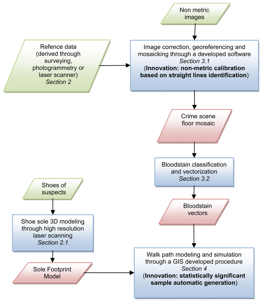
- the specific aim of the procedures described in this paper is to verify the compatibility of the walk paths performed on the crime scene by a suspect, with regards to the bloodstains present on the ground;
- the object of the crime scene mapping, for this specific work, is a floor covered by bloodstains.
- the availability of pictures taken by first aiders (law enforcement agents, forensic scientists, etc.), that provides information about the crime scene before items are moved or interfered with. Generally those pictures are acquired for record keeping purposes, focusing the attention on the semantic content and neglecting the geometric one, thus they are characterized by large geometric distortions that require an adequate modelling to be corrected;
- the availability of the shoes of the suspect (eventually of all the people whose movements on the crime scene have to be verified), to create a sole 3D model required as input data to reconstruct a specific sole footprint. The availability of the real shoes is critical because particular sole consumption shapes may affect significantly shape and extent of the contact surface.
2. Reference data acquisition
2.1. Sole footprint modeling
3. Crime scene mapping
- The goal is to analyze possible walk paths on the crime scene according to the bloodstain pattern on the floor;
- The object to be represented is the floor covered by the bloodstains. The floor can be considered essentially flat, if the results of the surveying network adjustment show height variations limited to few millimeters;
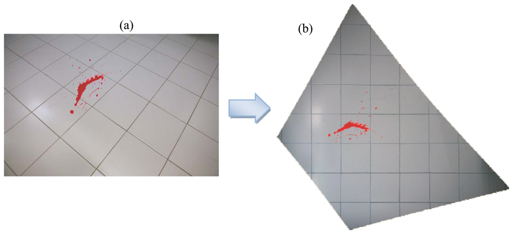
- The pictures acquired immediately after a criminal event represent the only available input data. Generally those pictures are acquired for record keeping purposes, thus the attention is focused on the semantic content neglecting the geometric one. Often the viewing direction is not plumbed to the floor, therefore the images are affected by large geometric distortions induced by the perspective;
- The images are generally acquired with non-metric variable focus cameras and equipped with zoom lenses. Therefore, both the internal orientation parameters of the camera (focal length and position of the principal point) and the lens distortions have to be considered unknown. In the case of non metric cameras the latter can have a value of hundreds of μm in the image plane. Because of the variable focus, these parameters are different for each image acquired with the same camera;
- Several linear entities are usually recognizable in the images (borders of floor tiles, walls edges, doors/windows edges).
3.1. Georeferencing and mosaicking of non metric images
- to generate a complete photo coverage using a single camera with particular lens and a unique focusing;
- to correctly position on the accident scene a sufficient number of markers, whose accurate coordinates have to be surveyed by means of geomatics techniques.
3.1.1. The lens distortion
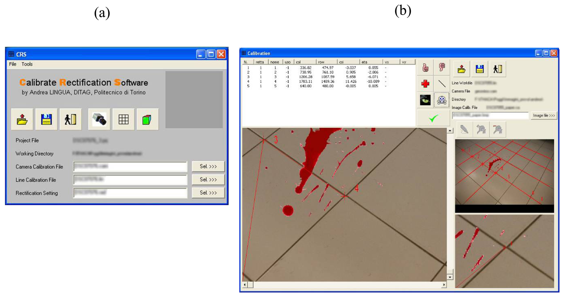
- identification of a certain number of straight lines (in the object space) covering the whole image to be calibrated and collimation of the frame coordinates (ξ′, η′) correspondent to the image coordinates distorted by the lens;
- definition of the straight lines in the ideal image space (not distorted) by the following equation:where i is the number of the identified straight lines
- definition of the straight lines equation respect to the measured coordinates (ξ′, η′) by the following:where:
- for each collimated point the equation (3) is linearised respect to the unknowns (mi, ni, k1, k2) using an approximate solution.
- a least square adjustment is performed, obtaining the desired k1 and k2 coefficients
- the analysis of some statistical parameters allows to estimate the adjustment results and the reliability of the estimated coefficients.
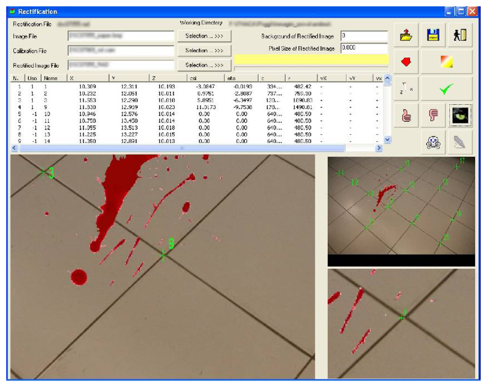
3.1.2. Photographic rectification and mosaicking
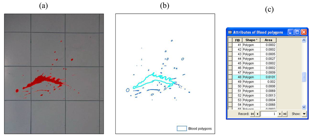
3.2. Data processing
4. Crime scene analysis
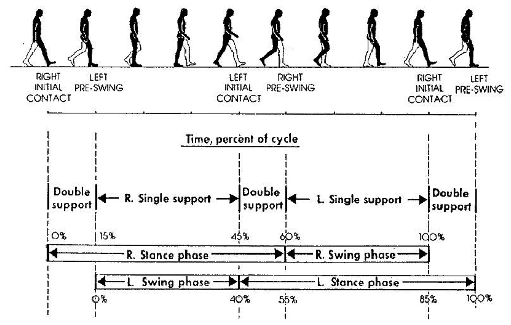
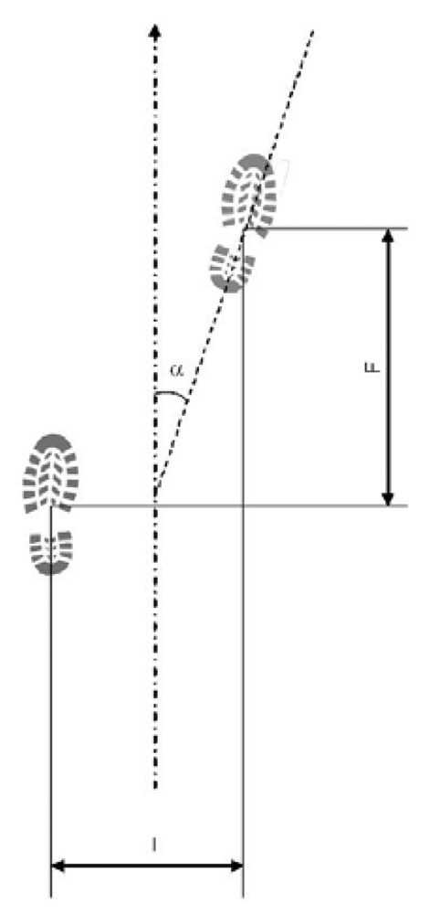
- Feet distance (I): distance between subsequent steps centroids (barycenters), calculated perpendicularly to walk direction;
- Stride (F): distance between subsequent steps centroids (barycenters), calculated parallel to walk direction;
- Rotation angle (α): step rotation in respect of walk direction.
- Feet distance (I): 5 – 20 cm;
- Stride (F): 20 – 40 cm (approximately 0.185 × body height in cm);
- Rotation angle (α): 0 – 15°.
4.1. Walk simulation and GIS based analysis
- n = sample numerosity;
- t = Student's t-distribution;
- Pexp = expected parameter variance;
- D = absolute precision required.
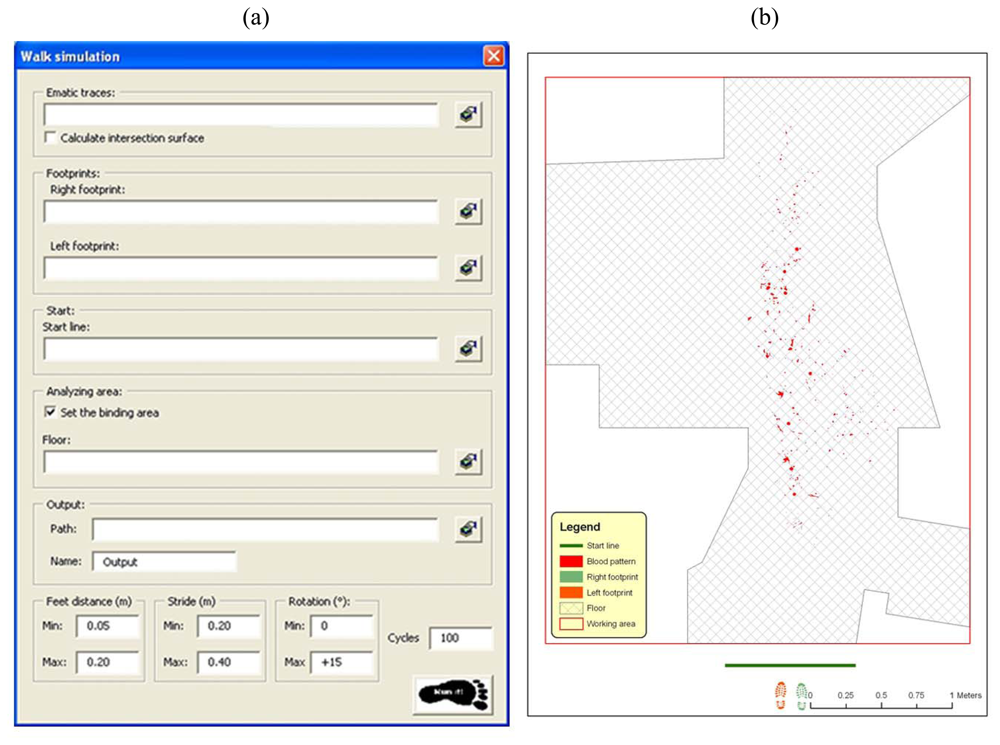
- The on floor delimitation of blood patterns (see Section 3.1.3), with possibility of storing total intersection surface for any single step;
- Left and right footprints derived from the 3D model of the shoe (see Section 2), considering uniquely the part of the shoe sole that touch a flat floor surface while walking. Sole hollows and non-flat surface are not considered while performing geometric intersections among objects;
- The start line of the foot walk, including all the assumed possible extent where first footprint may have occurred;
- The floor area, assumed as the possible walking area (optional). In the specific case it is the area resulting from the removal out of the floor surface of all not walkable areas;
- Minimum and maximum values for distances between feet;
- Minimum and maximum values for stride;
- Minimum and maximum values for rotation angles of every footstep;
- Number of computing cycles (sample dimension);
- Name and path for the output file.
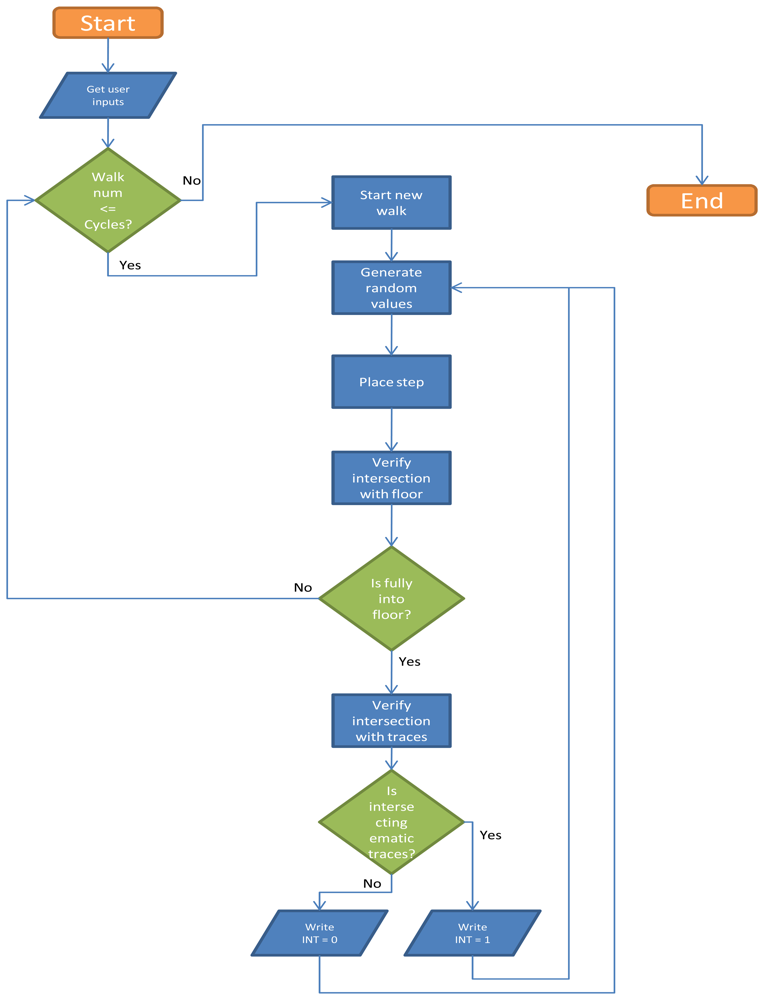
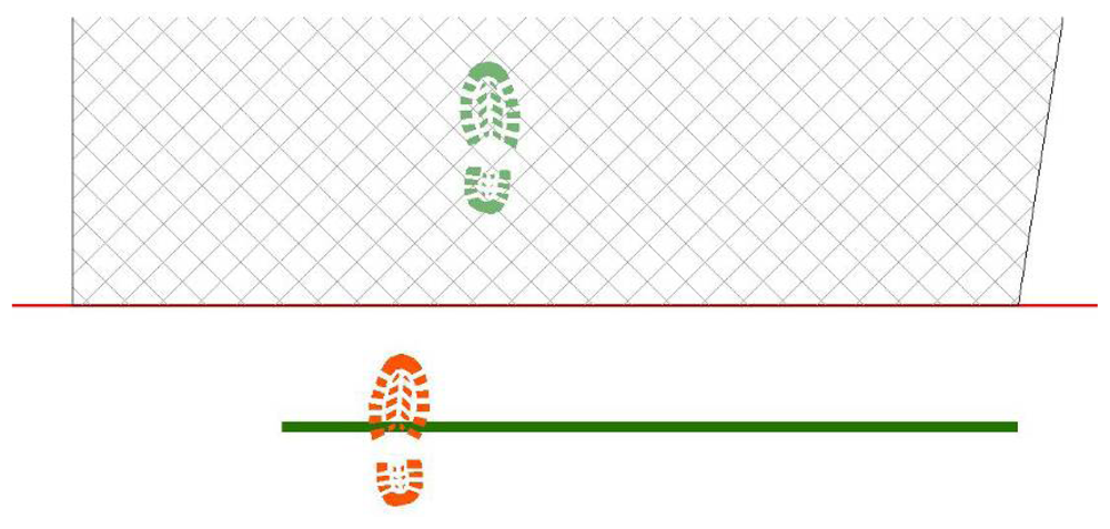
- First step is placed, casually choosing right or left footprint and in proximity of start line, in a casually chosen location (Figure 14);
- Next step values for feet distance, stride and angles are casually generated (according with limit values defined by the user) and new step position is calculated. According with that positioning information, a new feature is generated, using alternate, left or right, footprint shape (Figure 15). All positional parameters (center x and center y coordinates, feet distance, stride and angle) are stored in the associated table;
- (Optional) Intersection with floor area is performed (Figure 16). If footprint is fully contained by floor area (a), then procedure continues running. Otherwise (b), a new walk is generated (point 1). Intersection process result is stored in the associated table;
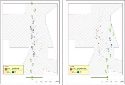
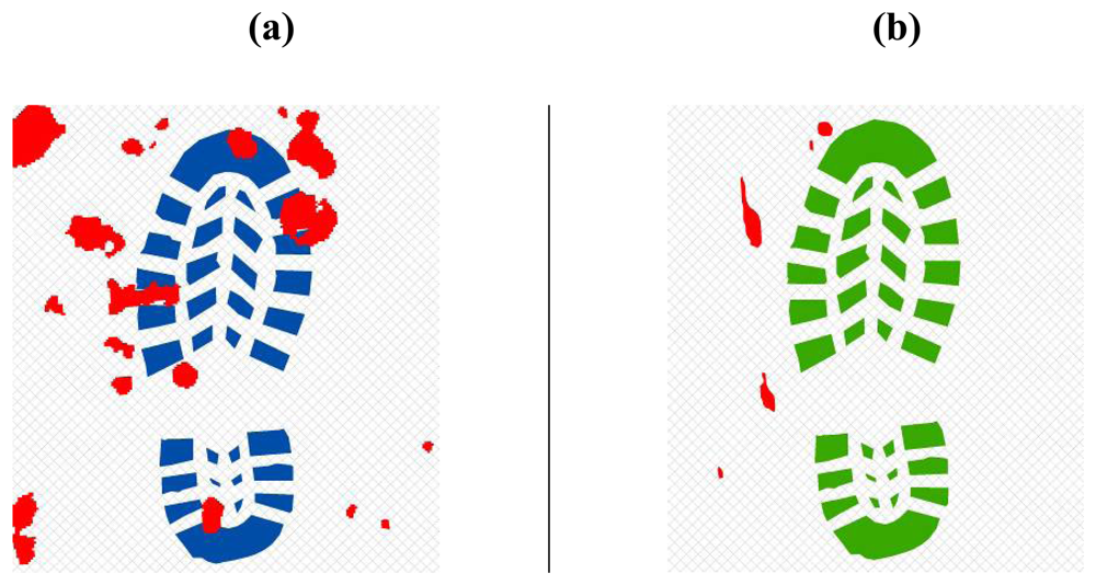
- Intersection with bloodstains is performed; intersection is verified when any part of a single multi-polygon geometry describing a step shares a common part with any polygon describing the ematic traces. Intersection process result is stored in the associated table. If intersection is verified (Figure 17a), the number of emetic traces intersected and the superimposition area (optional) are calculated and stored in the associated table. Otherwise (Figure 17b) the number of emetic traces intersected and the superimposition area are set to 0;
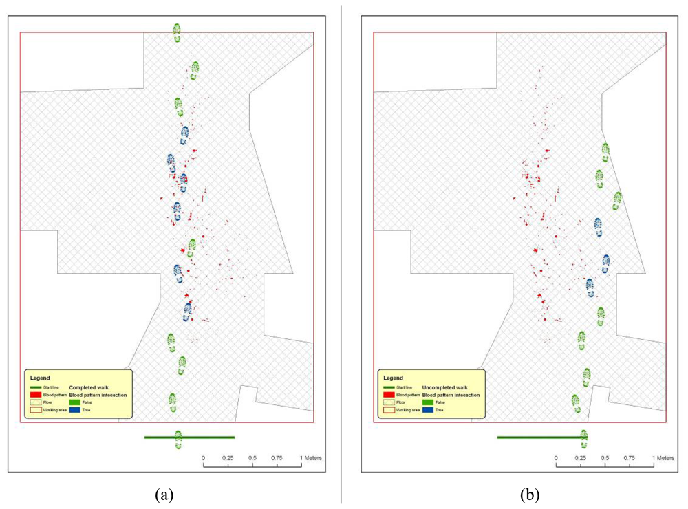
- Steps 2 to 4 are repeated until a new step overpass the top limit of the floor area (Figure 18). If walk loop concludes (no 3(b) events during walk generation process), all steps composing the walk are marked. If one or more steps of the walk has intersected bloodstains, the entire walk is marked. That help in easily discriminate entire walks in function of their main characteristics;
- Steps 1 to 5 are repeated until the number of walks is equal to the number of cycles decided by the user.
4.2. Outputs and results analysis
| SELECT Walk, count(Walk) as Cnt_Walk, sum(IntArea) as Sum_IntArea, |
| sum(W_IntFloor) as Sum_W_IntFloor, sum(IntAreaVal) as Sum_IntAreaVal, |
| sum(Shape_Area) as Sum_Shape_Area, avg(IntAreaNum) as Ave_IntAreaNum, |
| avg(IntAreaVal) as Ave_IntAreaVal |
| FROM [Table1] |
| GROUP BY Walk; |
5. Conclusions
Acknowledgments
References and Notes
- Spalding, R.P. Identification and Characterization of Blood and Bloodstains. In Forensic Science, An introduction to Scientific and Investigative Techniques, 2nd Ed.; James, S.H., Nordby, J.J., Eds.; Taylor & Francis: Washington, USA, 2005; pp. 244–245. [Google Scholar]
- Jenkins, B. Laser Scanning for Forensic Investigation. SparView 2005, 3, 21–22. [Google Scholar]
- Photogrammetric products: Production of digital cartographic products, GIS data, and 3D visualizations. In In Manual of Photogrammetry, 5th Ed.; McGlone, C.; Mikhail, E.; Bethel, J. (Eds.) ASPRS: Bethseda, Maryland, USA, 2004.
- Little, C.Q.; Peters, R.R.; Rigdon, J.B.; Small, D.E. Forensic 3D scene reconstruction. SPIE 2000, 3905, 67–73. [Google Scholar]
- Gibson, S.; Howard, T. Interactive reconstruction of virtual environments from photographs, with application to scene-of-crime analysis. Virtual Reality Software and Technolog, Proceedings of the ACM symposium on Virtual reality software and technology 2000, 41–48. [Google Scholar]
- Horswell, J. Crime scene photograpy. In The Practice Of Crime Scene Investigation; Horswell, J., Ed.; CRC: Boca Raton (FL), USA, 2004; pp. 125–138. [Google Scholar]
- Bornaz, L.; Lingua, A.; Rinaudo, F. Multiple scan registration in lidar close-range applications. Int. Arch. Photogram. Rem. Sens. Spatial Inform. Sci. 2003, 34, 72–77. [Google Scholar]
- Bornaz, L.; Porporato, C.; Rinaudo, F. 3D hight accuracy survey and modelling of one of Aosta's anthropomorphic stelae. CIPA Symposium 2007. [Google Scholar]
- Jung, J.W.; Bien, Z.; Lee, S.W.; Sato, T. Dynamic-footprint based person identification using mat-type pressure sensor. Eng. Med. Biol. Soc. 2003, 3, 17–21. [Google Scholar]
- Chi-Hsuan, L.; Hsiao-Yu, L.; Jia-Jin, J.C.; Hsin-Min, L.; Ming-Dar, K. Development of a quantitative assessment system for correlation analysis of footprint parameters to postural control in children. Physiol. Meas. 2006, 27, 119–130. [Google Scholar]
- Meuwly, D.; Margot, P.A. Fingermarks, shoesole and footprint impressions, tire impressions, ear impressions, toolmarks, lipmarks, bitemarks. A review (Sept 1998- Aug 2001). Forensic Science Symposium 2001, 16–19. [Google Scholar]
- http://www.sportspodiatry.co.uk/biomechanics.htm (last accessed on 08/08/2008)
- http://moon.ouhsc.edu/dthompso/gait/knmatics/stride.htm (last accessed on 08/08/2008)
- Bornaz, L.; Botteri, P.; Porporato, C.; Rinaudo, F. New applications field for the Handyscan 3D: the Res Gestae Divi Augusti of the Augustus temple (Ankara). A Restoration survey. CIPA Symposium 2007. [Google Scholar]
- Cameras and sensing systems. In Manual of Photogrammetry, 5th Ed.; McGlone, C.; Mikhail, E.; Bethel, J. (Eds.) ASPRS: Bethseda, Maryland, USA, 2004; pp. 652–668.
- Analytical photogrammetric operations. In Manual of Photogrammetry, 5th Ed.; McGlone, C.; Mikhail, E.; Bethel, J. (Eds.) ASPRS: USA, 2004; pp. 870–879.
- Temiz, M.S.; Kulur, S. Rectification of digital close range images: sensor models, geometric image transformations and resampling. Int. Arch. Photogram. Rem. Sens. Spatial Inform. Sci. 2008, 37. Part B5. Beijing 2008 (on CD-ROM). [Google Scholar]
- Hanke, K.; Grussenmeyer, P. Architectural Photogrammetry: basic theory, procedures, tools. ISPRS Commission 5 Tutorial 2002, 1–2. [Google Scholar]
- Fraser, C.; Hanley, H. Developments in close-range photogrammetry for 3D modelling: the iwitness example. Int. Arch. Photogram. Rem. Sens. Spatial Inform. Sci. 2004, 34. Part XXX (on CD-ROM). [Google Scholar]
- Fraser, C.; Hanley, H.; Cronk, S. Close-range photogrammetry for accident reconstruction. In Proceedings of Optical 3D Measurements VII; Gruen, A., Kahmen, H., Eds.; Univ. of Vienna: Vienna, 2005; Volume II, pp. 115–123. [Google Scholar]
- Fangi, G.; Gagliardini, G.; Malinverni, E. Photointerpretation and Small Scale Stereoplotting with Digitally Rectified Photographs with Geometrical Constraints. Proceedings of the XVIII International Symposium of CIPA; 2001; pp. 160–167. [Google Scholar]
- Karras, G.; Mavrommati, D. Simple calibration techniques for non-metric cameras. Proceedings of the XVIII International Symposium of CIPA; 2001; pp. 39–46. [Google Scholar]
- http://www2.unipr.it/∼bottarel/epi/campion/dimens.htm (last accessed on 08/09/2008)






| Field Name | Alias Name | Type | Length | Not Null |
|---|---|---|---|---|
| FID | FID | OID | 4 | Yes |
| Shape | Shape | Geometry | 0 | No |
| Id | Step ID | Integer | 4 | No |
| Walk | Walk ID | Integer | 4 | No |
| Step | Step sequence number in Walk | Integer | 4 | No |
| Feet | Right or Left feet | String | 5 | No |
| XCenter | X coordinate of the feature center | Double | 8 | No |
| YCenter | Y coordinate of the feature center | Double | 8 | No |
| Rot | Rotation angle | Double | 8 | No |
| Stride | Stride | Double | 8 | No |
| Distance | Feet distance | Double | 8 | No |
| IntArea | Intersection with bloodstains (1=true, 2=false) | Small Integer | 2 | No |
| IntFloor | Intersection with floor (1=true, 2=false) | Double | 8 | No |
| IntAreaVal | Feet surface touching bloodstains | Double | 8 | No |
| IntAreaNum | Number of intersected bloodstains | Small Integer | 2 | No |
| W IntArea | Walk intersection with bloodstains (1=true, 2=false) | Small Integer | 2 | No |
| W IntFloor | Walk Intersection with floor (1=true, 2=false) | Small Integer | 2 | No |
| Shape Length | Shape Length | Double | 8 | Yes |
| Shape_Area | Shape Area | Double | 8 | Yes |
| Field Name | Alias Name | Type | Length | Not Null |
|---|---|---|---|---|
| OBJECTID | FID | OID | 4 | Yes |
| Walk | Walk ID | Integer | 4 | Yes |
| Cnt_Walk | N. of steps composing Walk | Integer | 4 | Yes |
| Sum_IntArea | Total number of steps intersecting bloodstains | Integer | 4 | Yes |
| Sum_W_IntFloor | N. of steps completely inside the floor area | Integer | 4 | Yes |
| Sum_IntAreaVal | Total surface covered by bloodstains | Double | 8 | Yes |
| Sum_Shape_Area | Total walk surface | Double | 8 | Yes |
| Ave_IntAreaNum | Average number of steps intersecting bloodstains, in comparison with total n. of steps | Double | 8 | Yes |
| Ave_IntAreaVal | Average area intersecting bloodstains, in comparison with total area | Double | 8 | Yes |
© 2008 by the authors; licensee Molecular Diversity Preservation International, Basel, Switzerland. This article is an open-access article distributed under the terms and conditions of the Creative Commons Attribution license (http://creativecommons.org/licenses/by/3.0/).
Share and Cite
Agosto, E.; Ajmar, A.; Boccardo, P.; Giulio Tonolo, F.; Lingua, A. Crime Scene Reconstruction Using a Fully Geomatic Approach. Sensors 2008, 8, 6280-6302. https://doi.org/10.3390/s8106280
Agosto E, Ajmar A, Boccardo P, Giulio Tonolo F, Lingua A. Crime Scene Reconstruction Using a Fully Geomatic Approach. Sensors. 2008; 8(10):6280-6302. https://doi.org/10.3390/s8106280
Chicago/Turabian StyleAgosto, Eros, Andrea Ajmar, Piero Boccardo, Fabio Giulio Tonolo, and Andrea Lingua. 2008. "Crime Scene Reconstruction Using a Fully Geomatic Approach" Sensors 8, no. 10: 6280-6302. https://doi.org/10.3390/s8106280
APA StyleAgosto, E., Ajmar, A., Boccardo, P., Giulio Tonolo, F., & Lingua, A. (2008). Crime Scene Reconstruction Using a Fully Geomatic Approach. Sensors, 8(10), 6280-6302. https://doi.org/10.3390/s8106280


