Article

An influence of polyHEMA gate layer on properties of ChemFETs

by
Marek Dawgul
*,
Dorota G. Pijanowska
,
Alfred Krzyskow
,
Jerzy Kruk
and
Wladyslaw Torbicz
Institute of Biocybernetics and Biomedical Engineering of the Polish Academy of Sciences, ul. Ks. Trojdena 4, 02-109 Warsaw, Poland
*
Author to whom correspondence should be addressed.
Sensors 2003, 3(6), 146-159; https://doi.org/10.3390/s30600146
Submission received: 16 April 2003 / Accepted: 3 June 2003 / Published: 28 June 2003

Abstract

:
A complex deposition procedure of the hydrogel layer of modified poly(2- hydroxyethyl methacrylate) (polyHEMA) covalently linked to the silicon nitride surface and covering only the gate area of the ISFET, was optimized for photolithographic technology, using standard silicon wafers of 3” diameter. The influence of hydrogel composition and layer thickness on the sensors’ parameters was investigated. It was shown, that ISFETs covered with more than 100 µm thick polyHEMA layers in restricted pH-range could be practically insensitive to pH. Regarding mechanical stability of ion-selective sensors, a polyHEMA layer of ca. 20 µm thickness was found to be the best suitable for further manufacturing of durable ion selective sensors (Chemically modified Field-Effect Transistors – ChemFETs). The weak buffering properties of the thin polyHEMA layers had no disadvantageous influence on the sensors’ function.

Introduction

Progress in microelectronics and semiconductor technology enabled new capabilities in the field of sensor construction, particularly of pH sensors based on field-effect transistors (FETs) as transducers of chemical signal. Modification of the field-effect transistors by layers of various pH-sensitive materials (e.g. silicon, tantalum, aluminum, zirconium, hafnium oxides or silicon nitride) [1,2,3,4] enabled construction of miniaturized pH sensors (ion-sensitive field-effect transistors, ISFETs).
Positive results in studies on ISFETs have encouraged many research groups to modify these sensors and develop semiconductor-based sensors for determination of other ions and substances. One of research lines has based on physical deposition of an ion-selective polymeric membrane onto the ISFET gate insulator. In this way, the range of determined substances could be extended by utilization of experience of conventional ion-selective electrodes with liquid and polymeric membranes. It concerns particularly ionophores, which are responsible for the ability of sensors to detect defined substances. Unfortunately, deposition of the ion-selective polymeric membrane directly onto the ISFET gate insulator results in ill-defined phase boundary between membrane and gate insulator, what appears as considerable drift of output signal. Furthermore, influence of carbon dioxide as acidic agent on measurements is observed, which penetrates through the membrane to the gate surface and changes the potential of transistor transducer.
The problem of this ill-defined membrane-gate insulator interface has been solved by introducing poly(2-hydroxyethyl methacrylate) (polyHEMA) as a hydrogel material between the gate insulator and the sensing membrane. An important advantage of polyHEMA is the possibility of its deposition by means of photolithography [5]. In order to enable chemical coupling of the hydrogel, the gate insulator surface of SiO2 is silanized and in result, methacrylate groups, chemically bound to the substrate, are obtained, which can react with methacrylate monomers. Chemical binding of the methacrylate layer with the support is achieved by photochemical polymerization of 2-hydroxyethyl methacrylate. Further advantage of this material is the possibility of chemical binding of the ion-selective membrane to its surface.
The possibility of covalent anchoring of polyHEMA on the surface of silicon nitride, using photolithographic techniques for cross-linking of 2-hydroxyethyl methacrylate (HEMA), was already demonstrated [6]. In this paper, experiments on its optimization in regard to fabrication of ion-selective sensors with polymeric membranes are described.

Experimental

The aim of the presented work was optimization of the deposition method, leading to obtaining of polyHEMA layers of controlled thickness, and investigations on its effect on parameters of ion- selective sensors with polymeric membranes.

Chemicals

Chemicals for preparation of polyHEMA hydrogel layer:
-
2-hydroxyethyl methacrylate (HEMA), purum - Fluka, Buchs
-
3-trimethoxysilylpropyl methacrylate, purum - Fluka, Buchs
-
ethylene glycol dimethacrylate (EGDMA), purum - Fluka, Buchs
-
polyvinylpyrrolidone K-15 (PVP K-15), pract. - Fluka, Buchs
-
polyvinylpyrrolidone K-90 (PVP K-90), BioChemika - Fluka, Buchs
-
2,2’-dimethoxy-2-phenylacetophenone (DMPAP, photoinitiator), 99% - Aldrich
-
toluene, p.a. - POCh, Gliwice
-
2-butanone (ethyl methyl ketone), pure – CHEMPUR, Piekary Slaskie
-
ethanol, 95%
-
hydrogen peroxide solution, 3%
Components of ion-selective membranes:
-
nonactine, Selectophore® - Fluka, Buchs
-
potassium tetrakis(4-chlorophenyl)borate (KTpClPB), Selectophore® - Fluka, Buchs
-
Siloprene K 1000, Selectophore® - Fluka, Buchs
-
Siloprene Crosslinking Agent K-11, Selectophore® - Fluka, Buchs
-
tetrahydrofuran (THF) - Riedel de Haën or Fluka
Components of aqueous solutions for sensor characterization:
-
ammonium chloride, p.a. – POCh, Gliwice
-
sodium chloride, p.a. – Merck, Darmstadt or POCh, Gliwice
-
sodium dihydrogenphosphate, p.a. – POCh, Gliwice
-
sodium hydroxide, p.a., pre-weighed concentrate samples – POCh, Gliwice
-
hydrochloric acid, p.a., pre-weighed concentrate samples – POCh, Gliwice
Inert gas for photopolymerization at UV-light:
-
nitrogen, technically pure (99,9%) - Praxair, Warsaw

Equipment for Fabrication of PolyHEMA Hydrogel Coatings

Silanization

  • Round-bottomed flanged reactor of 1000 ml capacity, with five-necked cover, flange diameter 100 mm, reflux condenser, thermometer, Teflon sleeves for ground joints – Bibby Quickfit, Great Britain.
  • Electric heating mantles matching the reactor.
  • Autotransformer for power supply control of the heating mantle.

Photopolymerization

-
Centrifuge with controlled spin-rate for uniform distribution of liquid HEMA mixture onto 3”-wafers – Laboratory of Biochemical Sensors of the Institute of Biocybernetics and Biomedical Engineering of Polish Academy of Sciences (IBBE).
-
UV lamp – EPROM eraser, model 910 EE, MOMIK Electronics, Warsaw –- with additional accessories for fastening of mounted sensors and blowing through the casing with nitrogen, fabricated at the IBBE.
-
Photolithography station, consisting of illuminator with light-guide, power supply unit, wafer support with mask aligner and optical bench.
Wafer support with mask aligner was designed and fabricated at the IBBE. It serves aligning of 3”- wafers with ISFET structures with photo-mask, enabling deposition of photo-cured polymers on demanded wafer areas.
The photopolymerization proceeds in inert gas atmosphere. It is enabled by hermetic support and aligner casing blown through with nitrogen.

Characterization of the Partial Technological Processes

The deposition of the hydrogel layer is a multi-stage process, consisting of hydration, silanization, deposition of liquid HEMA cocktail, and photopolymerization.

Hydration

In order to increase the number of Si-OH groups on the surface of Si3N4, the wafers were hydrated by dipping in 3% hydrogen peroxide solution for 2.5 to 3 hours, and then left for drying overnight. Next day, after washing with ethanol, the wafers were silanized.

Silanization

The wafers were placed in a round-bottomed flanged reactor of 1000 ml capacity, equipped with reflux condenser and thermometer, containing mixture of composition as follows:
-
toluene: 450 ml,
-
3-(trimethoxysilyl)propyl methacrylate: 50 ml,
-
deionized water: 2 ml,
and were heated by an electric heating mantle for 4 hours at 80-82°C. After cooling of the mixture to about 30-35°C, the wafers were taken out from the reactor and washed four-times with 2-butanone. The fourth washing was proceeded in an ultrasonic bath. The wafers were left for drying overnight.
The wafer surface after hydration and silanization process looks apparently identical as the not chemically modified one (even if observed under a microscope). However, they have different chemical properties, in comparison with the not modified surfaces. The differences become appreciable only after deposition of hydrogel layer and its conditioning in water or aqueous electrolyte solution.

Deposition of Hydrogel Layer

In the next stage, liquid HEMA mixture was deposited onto the wafer and photochemically polymerized by UV-irradiation. In result, a coat of poly(2-hydroxyethyl methacrylate) covalently bound to the substrate is obtained:
Sensors 03 00146 i001
The excess of the non-polymerized HEMA cocktail is removed by washing with ethanol.

Optimization of Technology of PolyHEMA Layer Deposition for Coating of Wafers

The goal of the below presented experiments was optimization of the deposition method of polyHEMA under technological conditions, resulting in obtaining of ISFET structures covered with polyHEMA layers of controlled thickness. The investigated parameters were the cocktail composition and the spin rate and time.

Method 1 – PolyHEMA with PVP K-15 as a Filler

The HEMA cocktail of composition (A), given in Table 1, was spun on the wafer by means of a centrifuge at spin rate of about 500 min-1.
Table 1. Composition (A) of mixture for polyHEMA coatings with PVP K-15 as a filler, expressed in weight percent related to HEMA.
Additives to HEMAWeight percent related to HEMA
PVP K-1510%
DMPAP4%
EGDMA0.5%
The test was performed with use of a non-modified and a silanized wafer. On the surface of the non- modified wafer, the HEMA mixture could be spread as a thin layer. It was observed that several seconds after stop spinning some individual areas, not covered by the liquid mixture, appeared on the wafer surface. However, some extra movements with the wafer during carrying it from the centrifuge to the UV-light exposure set-up were sufficient to distribute the mixture over the uncovered regions. Finally, this effect had no significant influence on the quality of the polymerized hydrogel layer. In contrary, the HEMA uncovered areas on the silanized wafer enlarged very fast until the almost whole layer was flowed down (only individual, small droplets remained). The reason of this effect was a bad wettability of the wafer surface by liquid HEMA mixture. A very thick layer of HEMA mixture, spread on the wafer without spinning, stayed on the wafer surface for a short period and after several minutes almost completely flowed down. Additional washing of the wafer with ethanol and acetone on the centrifuge did not improve the wettability of the surface. It could be concluded that the bad wettability was not caused by insufficient washing of the wafer after silanization or its accidental contamination. Therefore, the deposition method of the liquid mixture had to be modified.

Method 2 - PolyHEMA with PVP K-15 as a Filler, with Additional Preparation of Silicon Nitride Surface and Increasing of the Thickness of Already Deposited PolyHEMA Layers

In this method, in which some extra preparation steps of the silicon nitride surface were performed, an improved wettability by the HEMA mixture of composition (A) was achieved, in comparison to the Method 1.
The wafer silanized with 3-(trimethoxysilyl)propyl methacrylate was stored on air. Next, the wafer was immersed in a bath consisting of 1 to 2 parts by volume of mixture (A) and 1 part by volume of ethanol for ca. 12 hours. Then, about 1-2 ml of mixture (A) was spread onto the wafer freshly taken out from the conditioning bath without washing. Initially the mixture showed not adequate wettability. The mixture was spun away from the wafer by means of a centrifuge on the maximal spin rate and the wafer was wiped dry with absorbent paper. This operation was performed three times. Each time a better wettability of the surface was observed. At the fourth portion of the liquid HEMA mixture, the wettability was satisfactory. It was spread at spin rate of ca. 500 min-1. Further treatment was the same as in the Method 1. A polyHEMA layer similar to that on the non-silanized wafer, covering only the demanded square-shaped areas was obtained.
The wafer was conditioned for 10 days in 0.1 M NaCl solution. The polyHEMA layer became soft, but it could not be torn off from the surface. It could be scratched off only in small pieces. The result of this test proved a covalent anchoring of the polyHEMA layer to the wafer surface of Si3N4.
The Method 2 was applied for fabrication of the first test series of ISFETs with polyHEMA coating on the gate area. The thickness of the polyHEMA layer was about 15-20 µm.
Due to the tendency to spontaneous flowing down of the low viscous HEMA mixture and problems with achievement of a satisfactory wettability of the wafer surface, a correct polyHEMA coating could be obtained on only ca. 70% of the ISFET structures. Gate areas of 30% of the structures were only partially coated or there was no polyHEMA deposited.

Increasing of Thickness of PolyHEMA Layer Deposited According to the Method 2

In the above-described method of polyHEMA deposition, it was impossible to achieve layer thickness greater than 15-20 µm. The first reason of that was the mentioned problem with adherence of the liquid HEMA mixture to the moment of irradiation by UV lamp. The second reason was the too small distance between the wafer and the mask, which could be achieved using a typical technological equipment and the risk of gluing together of the wafer with the mask in attempts of deposition of thicker layers of liquid HEMA mixture. In this situation, an attempt was made to increase the thickness of polyHEMA layer by dropping of additional portion of polyHEMA by means of a micropipette.
The increasing of the thickness of the polyHEMA layer was performed on structures covered with polyHEMA according to the Method 2. The structures were mounted as dipsticks on printed circuit boards, wired and encapsulated leaving an open window around the gate of about 2 mm diameter.
A droplet of HEMA mixture (of an optimal volume of 0.8 µl) was deposited by a micropipette on the gate areas of ISFETs, which were placed in the drawer of the UV lamp. The lamp housing was blown through with nitrogen in order to obtain oxygen-free atmosphere. After 5 minutes, the lamp was switched on for 6 minutes. The nitrogen inflow was cut off after 5 minutes from the moment of switching off the lamp. The ISFETs were left overnight in the closed housing of the lamp filled with nitrogen.
In this way, polyHEMA layers of total thickness of 100-150 µm were obtained. If smaller amounts of the HEMA mixture (about 0.5-0.6 µl) were placed on the ISFETs’ gate areas, an uniform coating was not possible to obtain, because the liquid mixture did not spill uniformly on the whole ISFET structure area not covered by encapsulation resin, but it gathered as droplet on its edge.

Method 3 - PolyHEMA with PVP K-90 as a Filler, with Addition of KCl Solution

The thickness of polyHEMA layers achieved according to the Method 2 seemed to be too small. Attempts to spread the liquid HEMA mixture at lower spin-rates did not give satisfactory results because the mixture shows tendency to spontaneous flowing off from the wafer surface.
In order to increase the viscosity of the HEMA mixture, its composition was changed (Table 2). Instead of polyvinylpyrrolidone K-15 of molar mass of about 10 000 used in the above-described experiments, polyvinylpyrrolidone K-90 of molar mass of about 360 000 was applied and subsequently 0.1 M aqueous potassium chloride solution was added. Polyvinylpyrrolidone K-90 well dissolves in methacrylate, so the mixture was homogenous after 2 hours of vigorous mixing by means of a laboratory shaker. The potassium chloride solution was added after mixing of organic components. The mixture showed a relative high viscosity and degassed very slowly after shaking, so it is recommended to prepare the mixture at least 1 day before use.
Table 2. Composition (B) of mixture for polyHEMA coatings with PVP K-90 as a filler, expressed in weight percent related to HEMA.
Additives to HEMAWeight percent related to HEMA
PVP K-9010%
DMPAP4%
EGDMA0.5%
0.1 M aqueous KCl solution40%
Due to the changed properties of HEMA mixture and the application of a new optical set-up (COBRABID OPTICA) and a different light source, the change of exposure time was also necessary. In this case, exposure time of 4.5 to 5 min was found to be optimal. At shorter exposure time the mixture was not fully polymerized – the coatings were soft (jelly-like) and dissolved partially in ethanol during washing of the wafer. At longer times of exposure the polymerization proceeded on the whole wafer surface.
It turned out that the HEMA mixture with PVP K-90 as a filler and 0.1 M KCl solution is excellent suitable for deposition of coatings by means of spin-off technique on the silanized silicon nitride substrates because it wets the wafer surface very good and it is possible to deposit a layer of demanded thickness by adjusting the spin rate and time. It has to be stressed that the application of this mixture eliminates the conditioning of the wafer in HEMA mixture diluted with ethanol and preliminary spinning of liquid HEMA mixture with simultaneous rubbing with absorbent paper, as it was described in the Method 2. The application of the new mixture allows to eliminate a laborious operation connected with a risk of wafer crack and to reduce the reagent consumption. An approximate dependence of deposited layer thickness on the spin rate and time is presented in Table 3. For the uniform distribution of the HEMA mixture on the wafer surface, a portion of 2 ml was found to be adequate. The time interval between the end of spinning and the beginning of UV irradiation resulted from the necessity of wafer transfer from the centrifuge to the mask aligner and the alignment of the mask with the wafer.
Table 3. Dependence of the thickness of deposited polyHEMA coatings on spin rate and time. Volume of liquid HEMA mixture dropped on the wafer – 2 ml. Time from the end of spinning to the beginning of irradiation – 5 min. Exposure time in nitrogen atmosphere – 5 min.
Test No.Spin
rate
Spin
Time
Coating thickness in µmISFET
structures
meanat wafer edge
1500 min-130 s60 – 100up to 160yes
2500 min-15 min40 – 60up to 120no
31000 min-15 min20 – 30up to 50no
41500 min-15 min15 – 25up to 40no
52000 min-15 min5 – 15up to 20no
61000 min-17 min15 – 2035*yes
* on individual structures up to 70 µm
The first test, with the shortest spin time, was performed for comparison with the method of deposition of polyHEMA with PVP K-15 as a filler, which was described earlier as the Method 2. In this way, polyHEMA coatings of considerable and differentiated thickness were obtained. It was an indication that the distribution of the liquid HEMA mixture had to be improved by extending the spin time. The goal of the tests 2 to 5 was the selection of a proper spin rate at constant spin time of 5 min. The goal of the last test was to obtain a polyHEMA coating of better uniformity and intermediate thickness between that obtained in tests 3 and 4. The differentiation of coating thickness was satisfactory. PolyHEMA coatings of increased thickness (up to 70 µm) were observed only near the wafer edge, on waste structures.

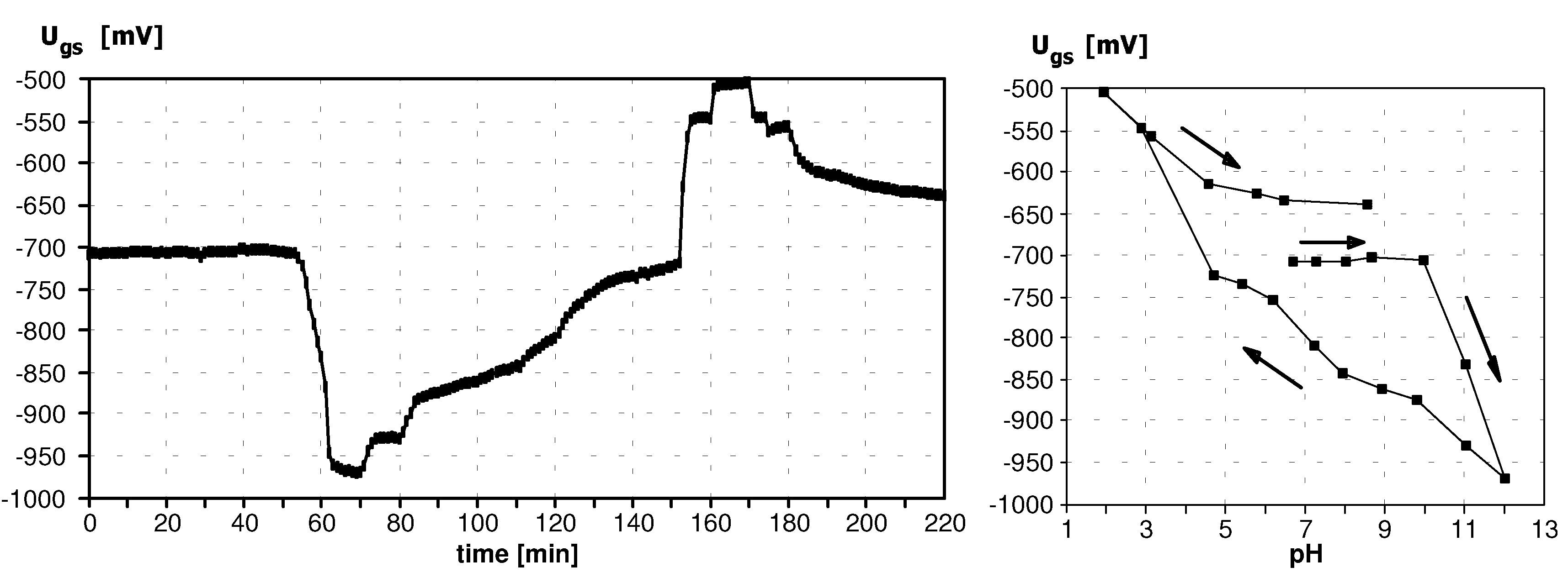
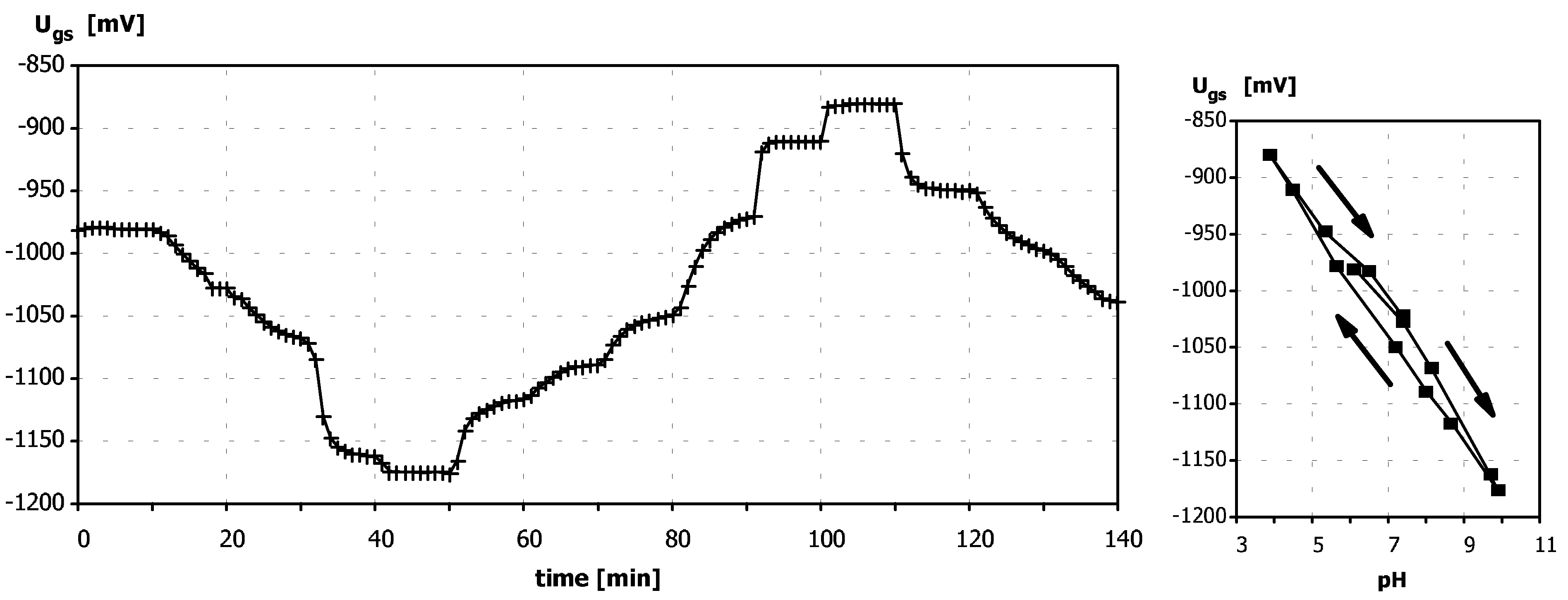
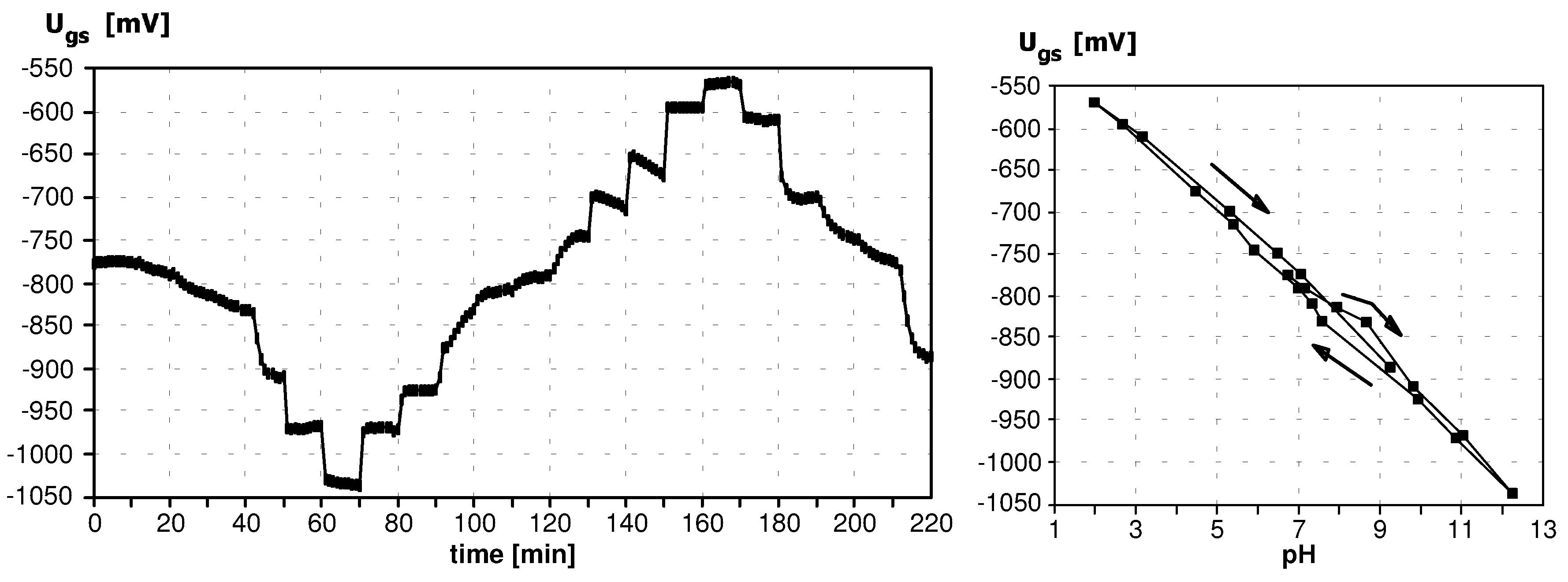
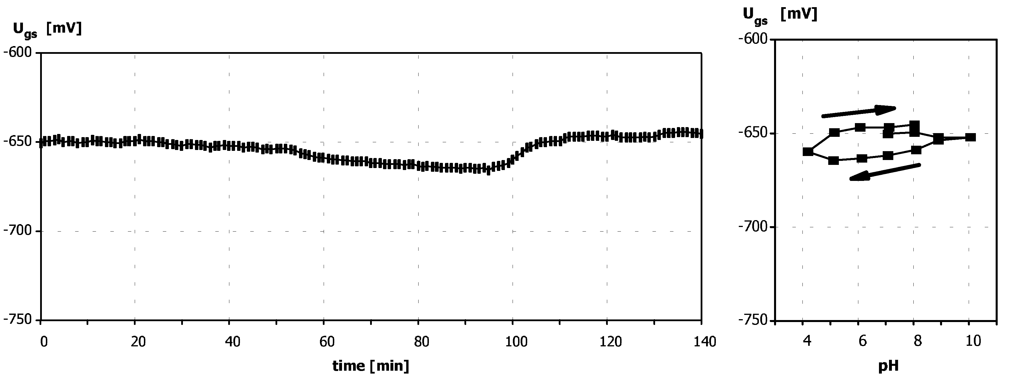
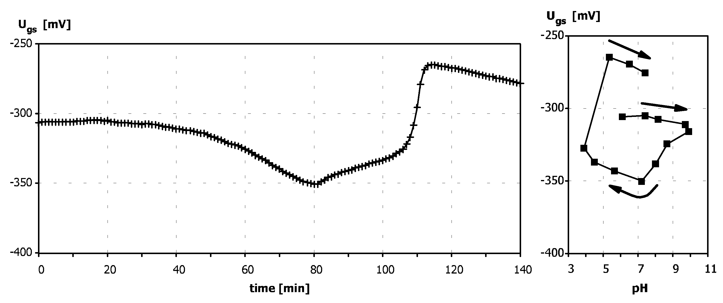
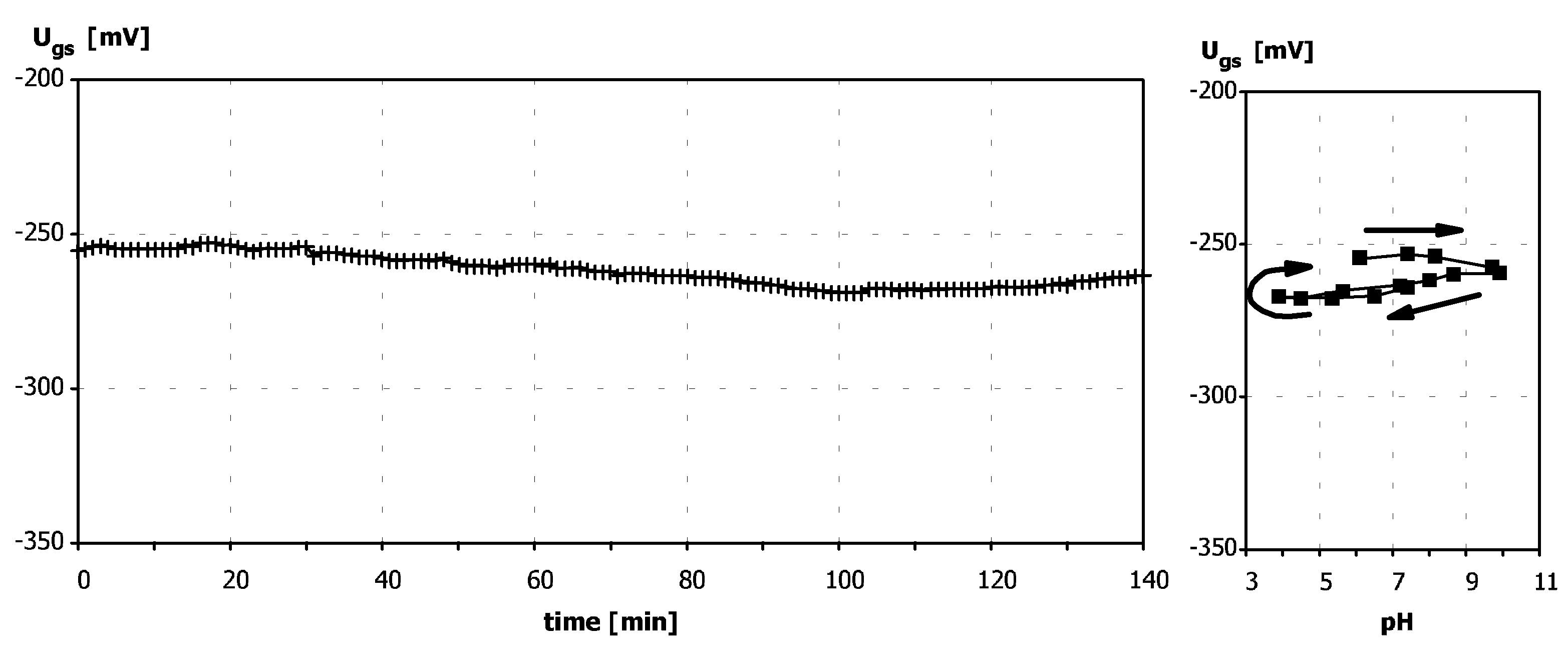
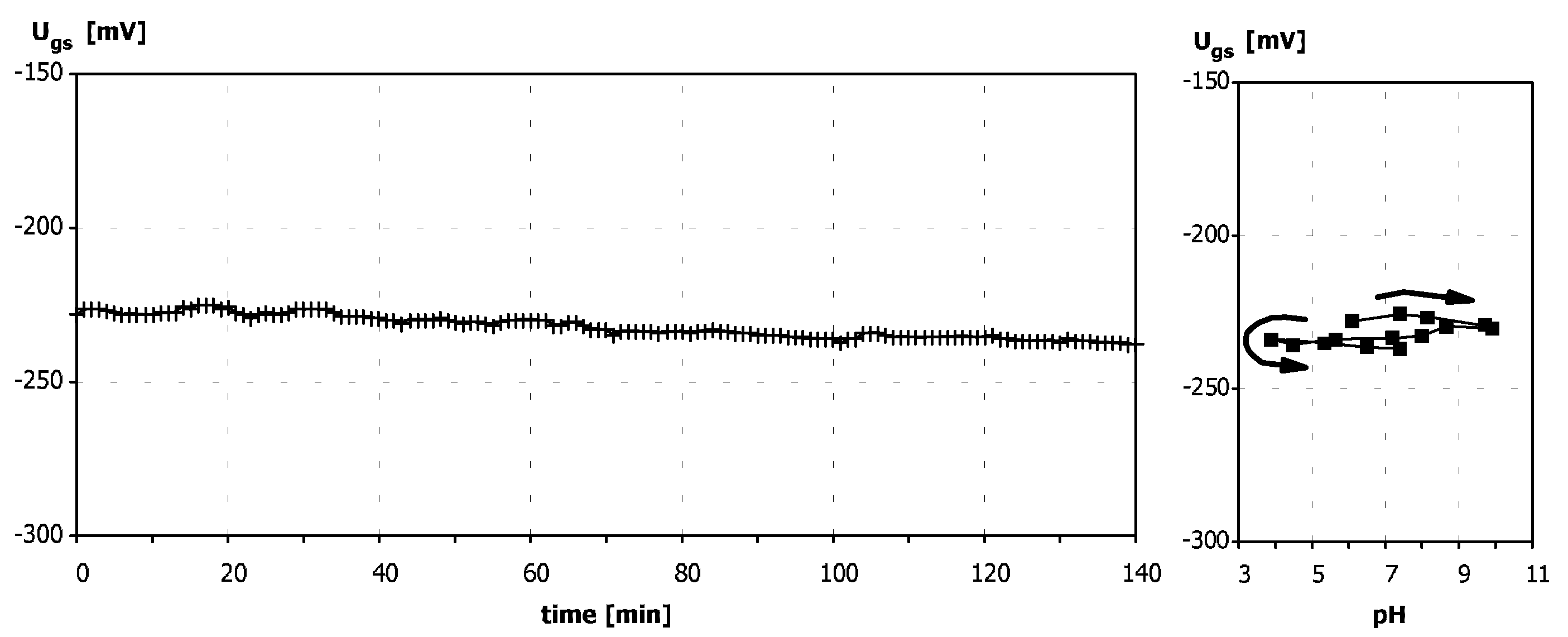
Characterization of ISFETs with Deposited PolyHEMA Layer

Sensitivity to pH

For ISFETs with polyHEMA coatings obtained by means of the above-described methods, pH-response characteristics were performed in order to verify the buffering properties of the polyHEMA. The measurements were carried out after conditioning of the ISFETs in phosphate buffer for 18 hours.
Measurements of Ugs values of ISFETs were performed in buffer solution containing sodium dihydrogenphosphate at concentration of 0.005 M and sodium chloride at concentration of 0.1 M at pH = 6 or pH = 7 (adjusted by addition of sodium hydroxide). The pH value was changed by one unit in range from 2 to 12 or from 4 to 10 by addition of HCl or NaOH solution by means of autoburette. The pH value measured by means of glass electrode was taken. The Ugs values were recorded every one minute during the whole measuring cycle. The Ugs value read after 10 minutes from the moment of change of analyte concentration (signal in steady state) was taken for determination of the calibration curve. Assumption of 10 minutes measuring period for every calibration point enabled control of signal stability and evaluation of sensor functioning.
Figure 1. Response to pH changes of an ISFET with polyHEMA coating deposited according to the Method 2. Cycle of pH changes: 7-12-2-9.
Sensors 03 00146 g001
A typical example of the pH-characteristic of an ISFET with polyHEMA coating deposited by the Method 2 (polyHEMA with PVP K-15, thickness 15-20 µm) is presented in Fig. 1.
The pH-response was almost unchanged in comparison to a non-modified ISFET (slope more than 45 mV/dec.). Only a longer response-time in pH-range from 6 to 9 and a deformation of the dynamic response in pH-range from 2 to 5 were observed. Such behavior of the sensor can testify to a too small thickness of the polyHEMA coating.
In corroboration of this hypothesis, an analogical characteristic was performed for the sensor with the same coating which thickness was increased by dropping of additional portion of HEMA by means of micropipette. The characteristic of this sensor is presented in Fig. 2. As can be seen, in pH range from 5 for 10, the modified polyHEMA coating shows distinctly improved buffering properties. Moreover, the sensor shows a considerable hysteresis. It can be also seen, that at pH values above 10 and below 4, a breakdown of buffer capacity of the polyHEMA layer proceeds, combined with memory effect.
It is confirmed by the pH-characteristic of the same sensor obtained in the restricted pH range, i.e. from 4 to 10, presented in Fig. 3. Under these conditions, the sensors show no response to pH. Further measurements were performed in pH-range from 4 to 10 only, because this range was accepted as sufficient from the point of view of further sensors’ applications.
The influence of polyHEMA layer thickness can be best observed on the example of polyHEMA layers made of polyHEMA with PVP K-90 as a filler. The pH-characteristics in the range from 4 to 10 were performed for sensors with polyHEMA membranes deposited entirely by means of photolithography after spreading the liquid HEMA mixture using “spin-off” technique (Fig. 4, Fig. 5, Fig. 6 and Fig. 7). In the case of coatings 20 µm thick, a deformation of the dynamic response due to prolonged response time to pH is observed (Fig. 4).
For coating ca. 60 µm thick, the sensor characteristic (Fig. 5) is probably a resultant of buffering properties of the polyHEMA coating, a very long response time and breakdown of the buffer capacity combined with a memory effect.
Figure 2. Dynamic response and calibration curve to pH of an ISFET with polyHEMA coating deposited according to the Method 2, with subsequently increased thickness by dropping of additional portion of HEMA by means of micropipette. Cycle of pH changes: 6.5-12-2-8.5.
Sensors 03 00146 g002
Figure 3. Dynamic response and calibration curve to pH of an ISFET with polyHEMA coating deposited according to the Method 2, with subsequently increased thickness by dropping of additional portion of HEMA cocktail by means of micropipette. Cycle of pH changes: 7-10-4-8. (Measurements performed for the same ISFET as in Fig. 3, but in restricted pH-range).
Sensors 03 00146 g003
The polyHEMA coating ca. 100 µm thick ensures that practically no response to pH can be observed (Fig. 6). Further increasing of the coating thickness (up to 160 µm) leads to more stable output signal in the whole measuring range (Fig. 7).ISFETs with polyHEMA coatings were tested as basic structures in ammonium ion-selective sensors. Comparative studies were performed on the example of ion- selective membranes of Siloprene with entrapped nonactine. These membranes have been regarded as the most reliable among membranes, described earlier in [7, 8], which were tested on ISFETs with SiO2 gate insulator covered with polyHEMA, fabricated by Sentron in the Netherlands.Dynamic responses and calibration curves of ammonium sensors were performed by registration of Ugs changes resulting from addition of ammonium chloride standard solutions at concentrations of 0.1 M and 1 M to sodium chloride solution at concentration of 0.1 M. The Ugs values were recorded every one minute during the whole measuring cycle. The Ugs value read after 10 minutes from the moment of change of analyte concentration was taken as the value for the calibration curve.
The ion-selective sensors (ChemFETs), prepared using ISFETs fabricated by the Institute of Electron Technology in Warsaw, showed chemical characteristics (dynamic responses and calibration curves) comparable with the sensors based on Dutch semiconductor structures. It was stated that the composition and thickness of the polyHEMA coating does not have significant effect on the electrochemical characteristic of the sensor.
Figure 4. Dynamic response and calibration curve to pH of an ISFET with polyHEMA coating ca. 20 µm thick, deposited according to the Method 3. Cycle of pH changes: 6-10-4-7.
Sensors 03 00146 g004
Figure 5. Dynamic response and calibration curve to pH of an ISFET with polyHEMA coating ca. 60 µm thick, deposited according to the Method 3. Cycle of pH changes: 6-10-4-7.
Sensors 03 00146 g005

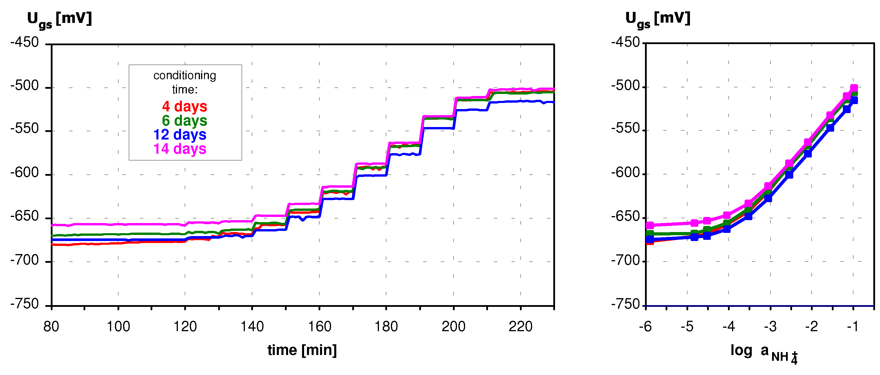
Application of ISFETs wth PolyHEMA Coatings to Construction of Ion-Selective Sensors

The only difference concerned the fabrication repeatability of correctly operating sensors and their lifetime. On the ground of visual control of the defective sensors, it was stated that the mechanical properties of polyHEMA coatings, resulting from their thickness, have considerable influence on the reproducibility of ion-selective sensors’ fabrication and their li fetime.
Figure 6. Dynamic response and calibration curve to pH of an ISFET with polyHEMA coating ca. 100 µm thick, deposited according to the Method 3. Cycle of pH changes: 6-10-4-7.
Sensors 03 00146 g006
Figure 7. Dynamic response and calibration curve to pH of an ISFET with polyHEMA coating ca. 160 µm thick, deposited according to the Method 3. Cycle of pH changes: 6-10-4-7.
Sensors 03 00146 g007
The worst results were obtained for sensors with polyHEMA coatings 60 µm thick and thicker. The ion-selective membranes showed an almost complete lack of adhesion to the polyHEMA coating soaked with aqueous electrolyte solution. Considerable differences in flexibility and hardness between polyHEMA coatings and Siloprene membranes could cause a strong mechanical stress in their
Figure 8. Dynamic responses and calibration curves of an ammonium ion sensor with membrane of Siloprene K 1000, fabricated on ISFET structure with silicon nitride gate insulator.
Sensors 03 00146 g008
interfacial zone and subsequently, detaching of the Siloprene membrane. Furthermore, it was not possible to deposit ion-selective membranes of uniform thickness on the top of the very thick, square- shaped polyHEMA coatings fabricated by means of photolithography.
On the other hand, ISFETs with polyHEMA coatings 15-20 µm thick (fabricated according to the Method 2) and 20 µm thick (deposited according to the Method 3), independent on the filler (PVP K-15 or PVP K-90) could be successfully used for the construction of durable ammonium ion sensors. The Siloprene membrane showed a good adhesion to the polyHEMA-coated substrate. The weak buffering properties of thin polyHEMA layers had no disadvantageous influence on the sensors’ function, even during pH changes of the measuring solution containing ammonium ions. Probably, the hydrophobic ion-selective membrane of Siloprene ensures sufficient insulation of the polyHEMA hydrogel from the measuring solution.
The sensors prepared in this way worked correctly: they showed a stable output signal and a near- Nernstian slope. An exemplary characteristic of a sensor of this type is presented in Fig. 8.

Conclusions

A deposition method of a durable, chemically anchored to the silicon nitride surface, layer of modified poly(2-hydroxyethyl methacrylate) (polyHEMA), ensuring thermodynamically well-defined phase boundaries between the ion-selective membrane and the gate insulator of the ISFET was developed and optimized. It was stated, that the HEMA mixture with PVP K-90 as a filler and 0.1 M KCl solution is excellent suitable for deposition of coatings by means of spin-off technique on the silanized silicon nitride substrates, because it wets the wafer surface very good and it is possible to deposit a layer of demanded thickness by adjusting the spin rate and time.
The influence of the polyHEMA thickness on the pH-sensitivity of the ISFETs was tested. It was shown, that ISFETs covered with more than 100 µm thick polyHEMA layers in restricted pH-range could be practically insensitive to pH.
ISFETs with polyHEMA layers were tested as transducers for ammonium ion sensors with polymeric ion-selective membranes. It turned out, that the composition and thickness of the polyHEMA coating does not have significant effect on the electrochemical characteristic of the sensors. On the other hand, significant differences concerned the fabrication repeatability of correctly operating sensors and their lifetime occurred. Only ISFETs with polyHEMA coatings up to 20 µm thick, independent on the filler (PVP K-15 or PVP K-90), could be successfully used for the construction of durable ammonium ion sensors. The Siloprene membrane showed good adhesion to the polyHEMA-coated substrate. The weak buffering properties of thin polyHEMA layers had no disadvantageous influence on the sensors’ function. The sensors prepared in this way worked correctly: they showed a stable output signal and a near-Nernstian slope.

References

  1. Bergveld, P.; Sibbald, A. Analytical and biomedical applications of ion-sensitive field effect transducers; Elsevier Science Pub. B.V.: Amsterdam, 1988. [Google Scholar]
  2. Torbicz, W. Theory and properties of field effect transistors as biosensors; Ossolineum: Wroclaw, 1988. [Google Scholar]
  3. Pijanowska, D.; Torbicz, W. Long-term stability of Si3N4, Al2O3 and Ta2O5 gate pH-ISFETs. Proc. of SPIE - The Int. Society for Optical Engineering on Optoelectronic and Electronic Sensors, USA 1995, 2634, 210. [Google Scholar]
  4. Torbicz, W.; Pijanowska, D. ISFETs Instability Problems and Methods of their Minimization for Long-term pH Monitoring Purposes. Biocybernetics and Biomedical Engineering 1996, 16(1–2), 71–91. [Google Scholar]
  5. Sudhölter, E. J. R.; van der Wal, P. D.; Skowronska-Ptasinska, M.; van den Berg, A.; Bergveld, P.; Reinhoudt, D. N. Anal. Chim. Acta 1990, 230, 59.
  6. Dawgul, M.; Jazwinski, J.; Koszur, J.; Brzozka, Z.; Torbicz, W. Development of an intermediate hydrogel layer for chemically modified FET based on Si3N4. In Proc. of Eurosensors XI, The 11th European Conference on Solid State Transducers, Warsaw, Poland, September 21-24, 1997; 1275.
  7. Brzózka, Z.; Dawgul, M.; Pijanowska, D.; Torbicz, W. Development of NH4+-sensitive polymer membranes for long term performance microsensor. Proc. of SPIE - The Int. Society for Optical Engineering on Optoelectronic and Electronic Sensors 1996, 3054, 187–196. [Google Scholar]
  8. Brzózka, Z.; Dawgul, M.; Pijanowska, D.; Torbicz, W. Durable NH4+-sensitive CHEMFET. Sensors and Actuators B 1997, 44, 527–531. [Google Scholar]
  9. Pijanowska, D.; Torbicz, W. Long-term stability of Si3N4, Al2O3 and Ta2O5 gate pH-ISFETs. Proc. of SPIE - The Int. Society for Optical Engineering on Optoelectronic and Electronic Sensors, USA 1995, 2634, 210. [Google Scholar]
  • Sample Availability:

