
Aerodynamics Analysis of Helicopter Rotor in Flight Test Using Strain Gauge Sensors


Abstract
1. Introduction
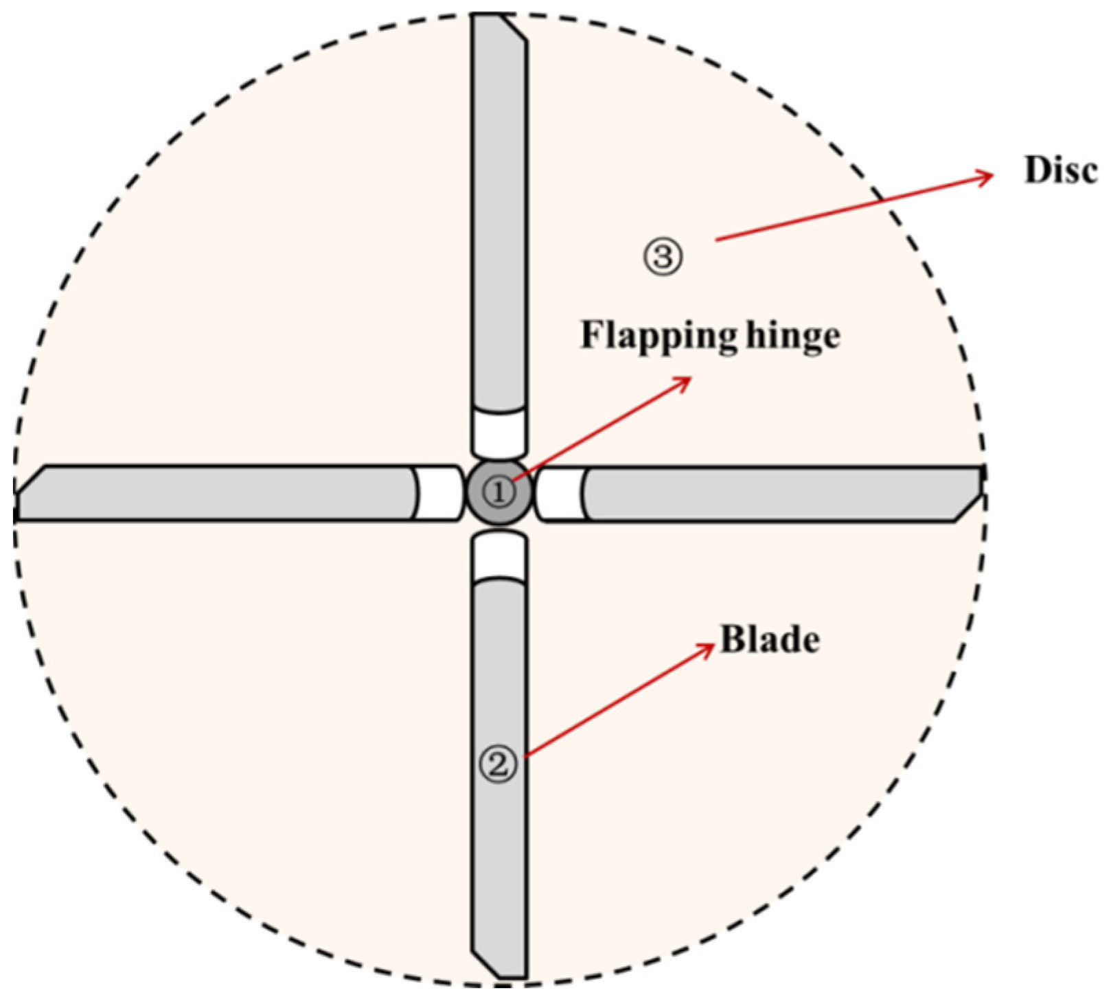
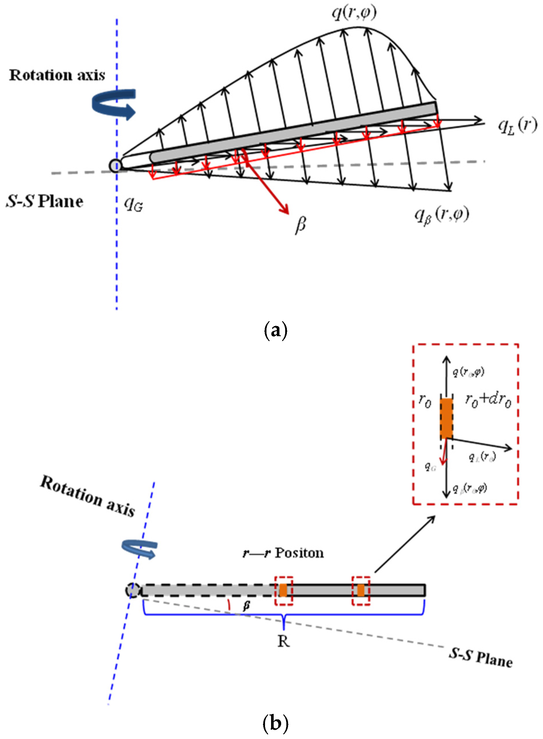
2. Flapping Motion Model with Strain
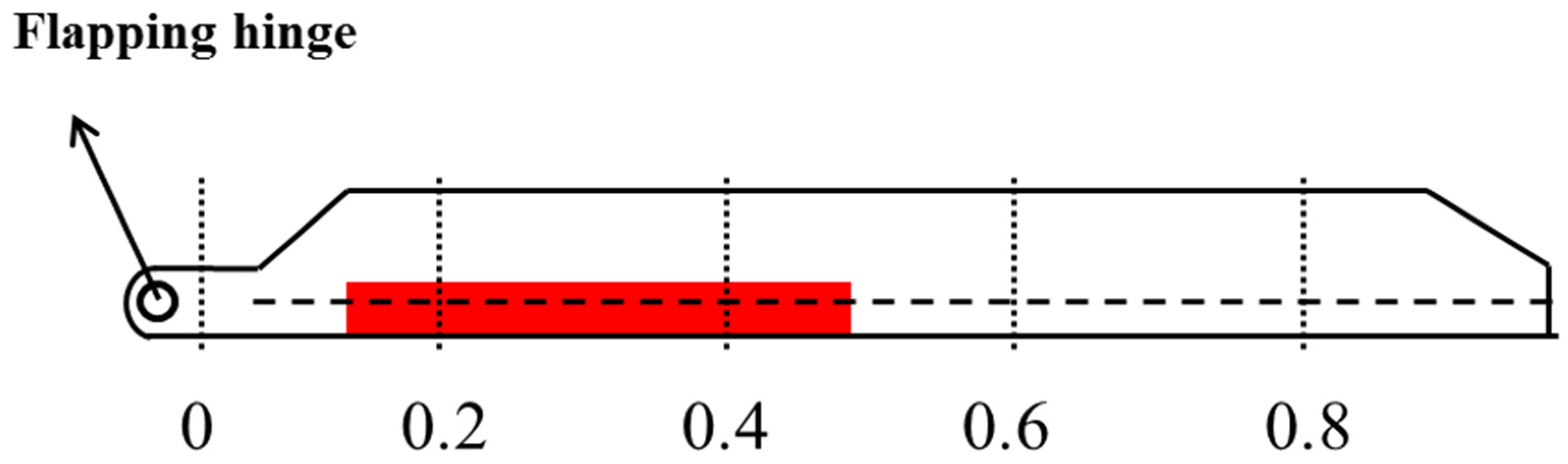
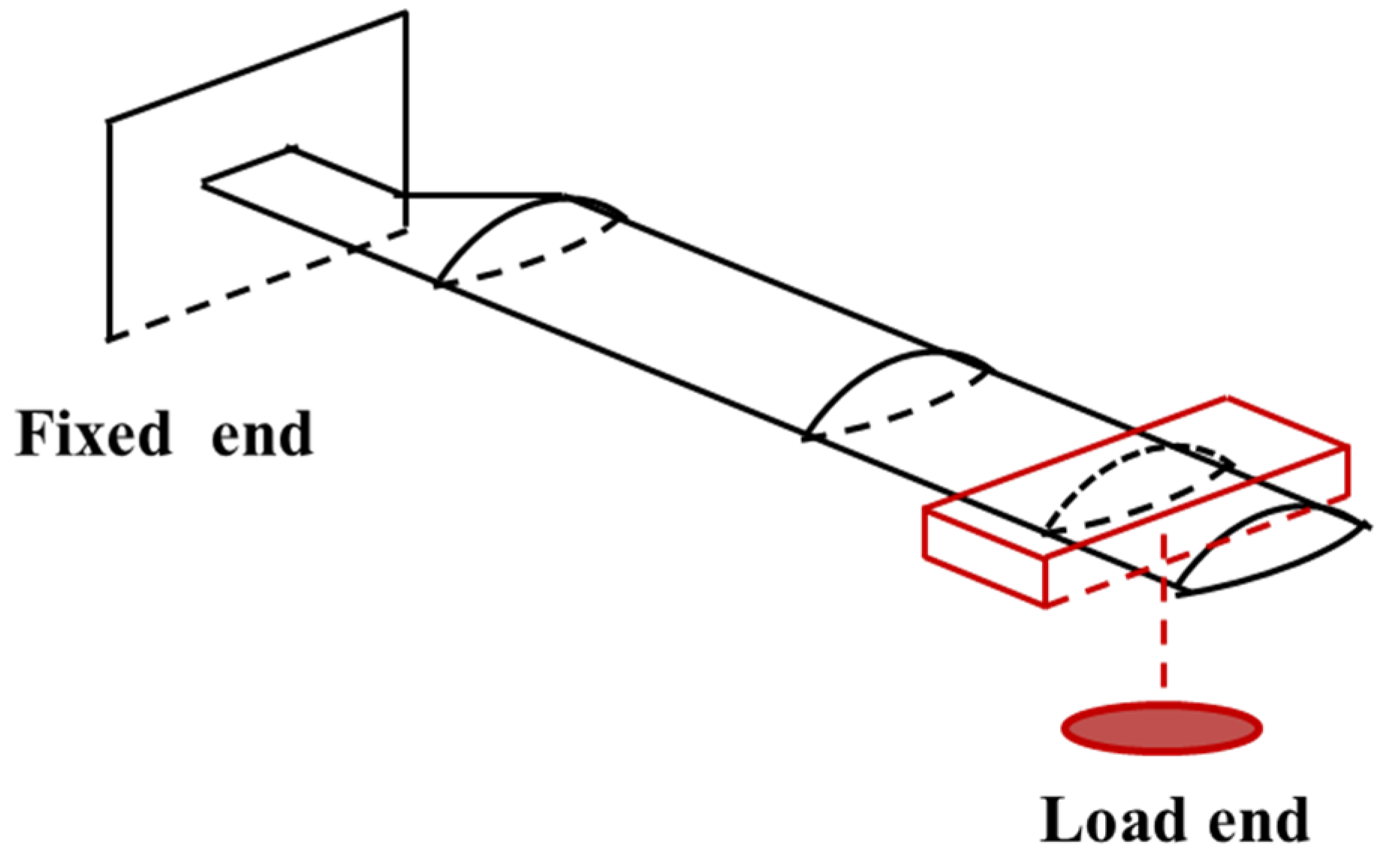
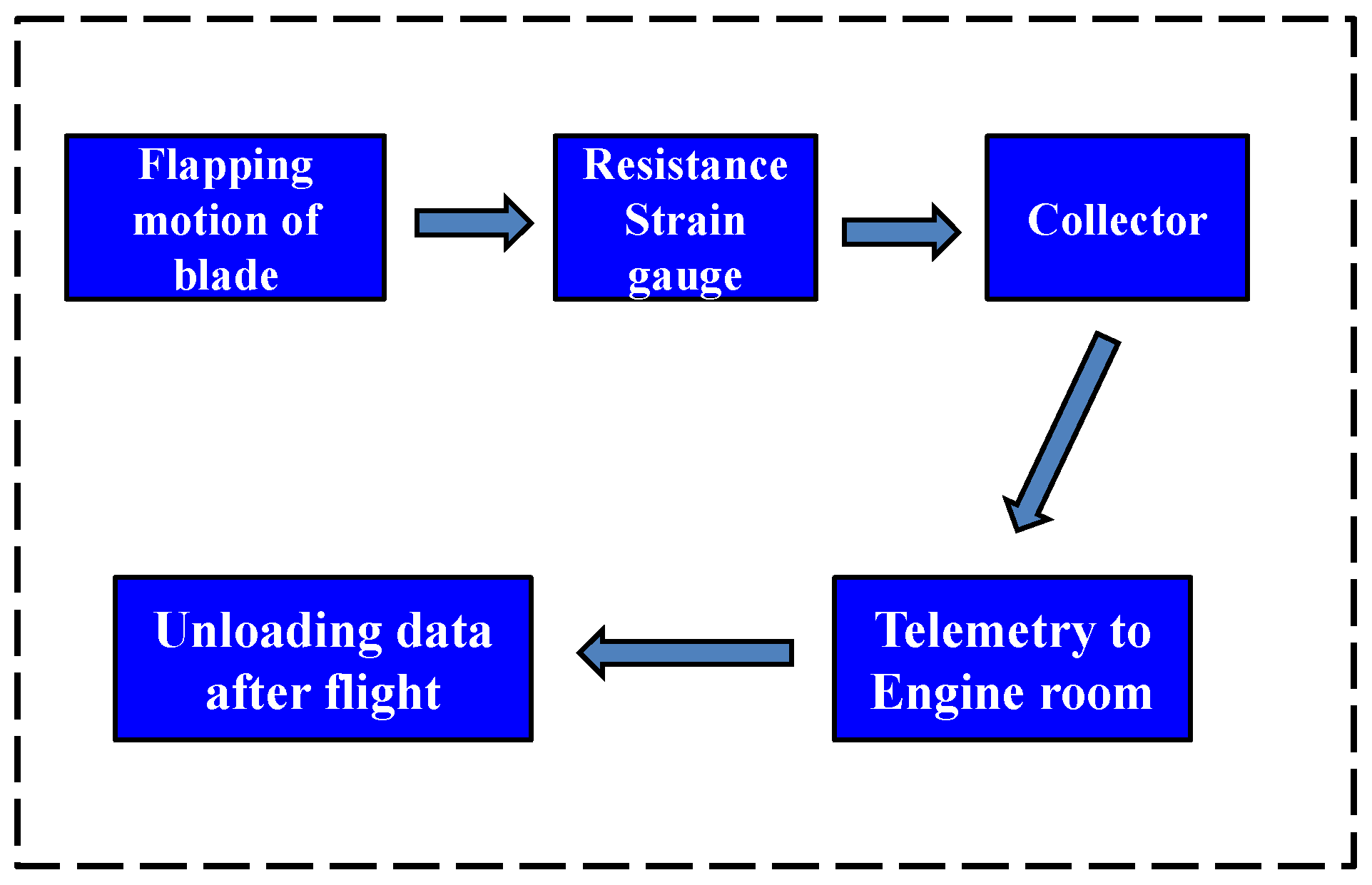
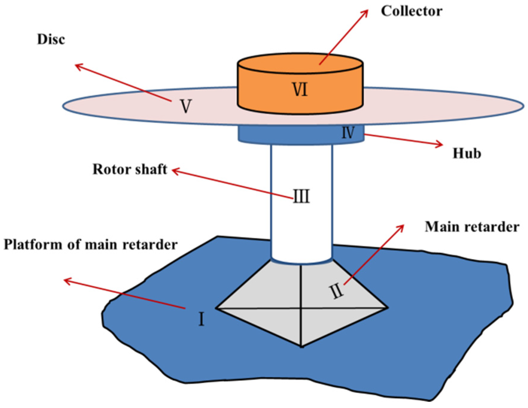
3. The Flight Measurement of Blade Strains
4. Calculation of Aerodynamics
5. Conclusions
- (1)
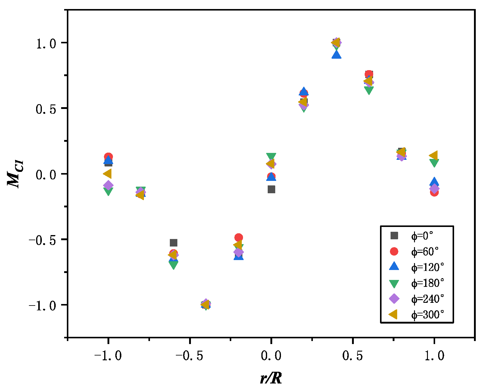
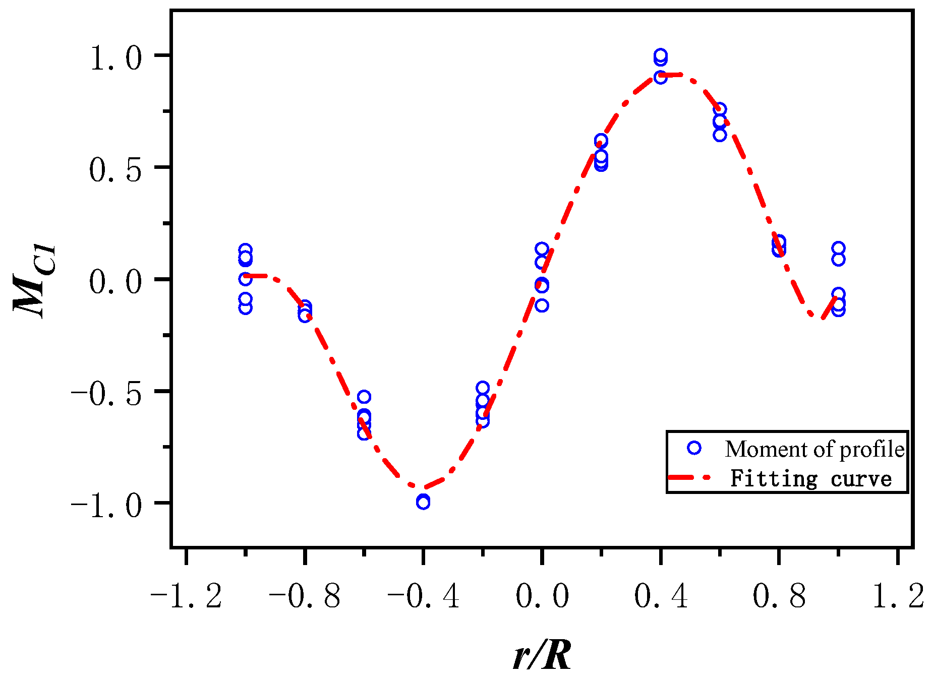
- The radial distribution of flapping moment increases first and then decreases, which is related to the existence of flapping hinge, and the maximum moment load is about r = 0.4;
- (2)
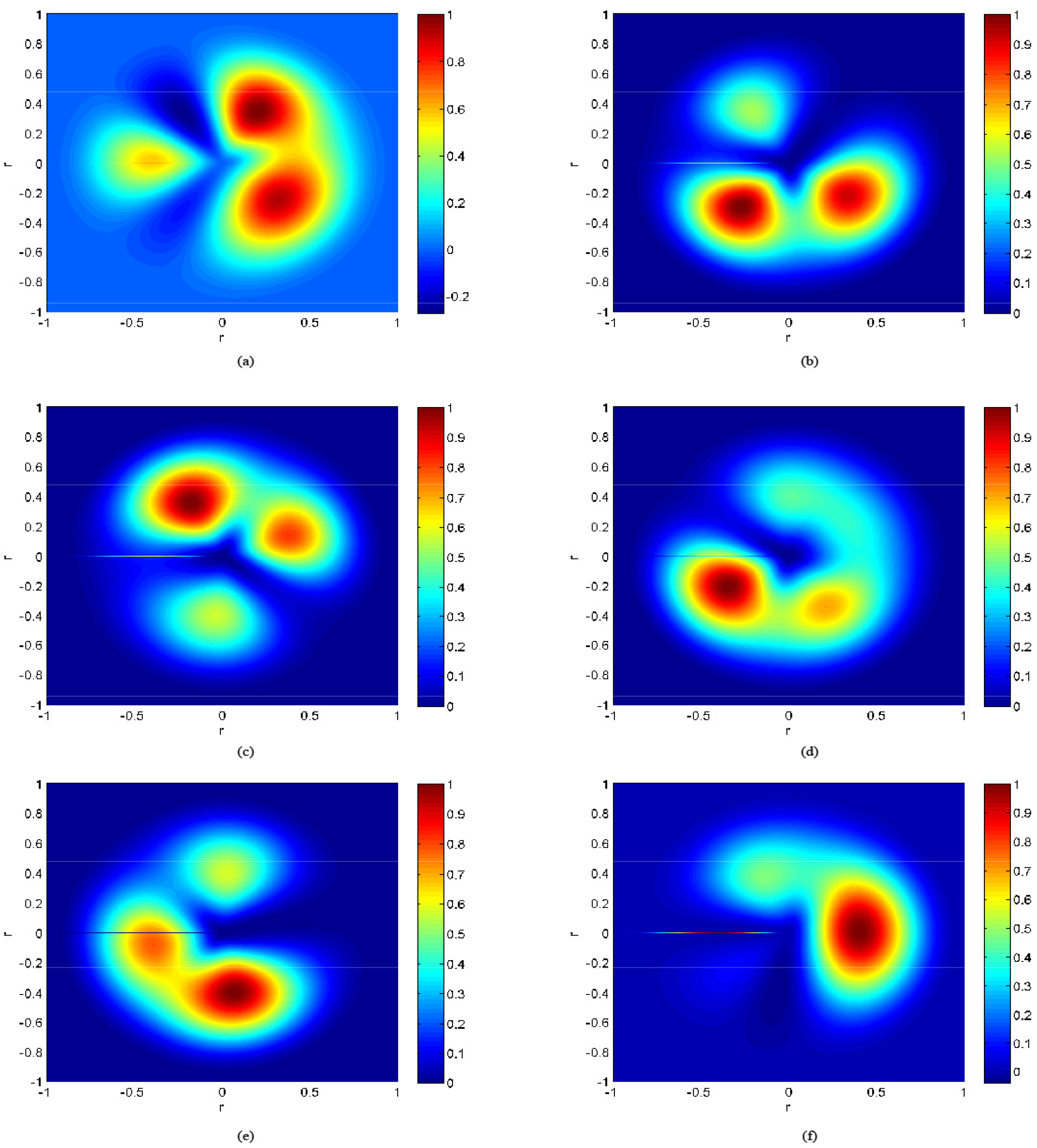
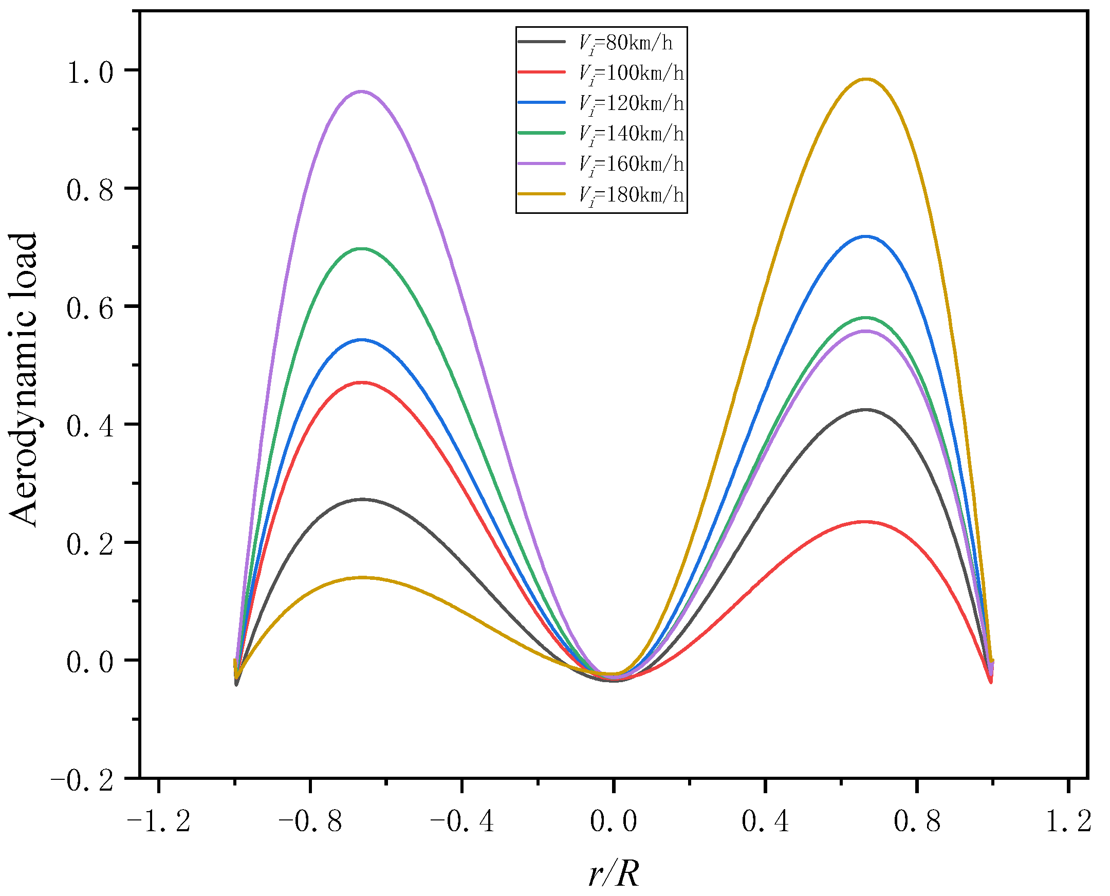
- The radial distribution of aerodynamic force increases first and then decreases, which is related to the existence of the flow field of blades, and the maximum aerodynamic force is about r = 0.7 which is consistent with the calculation results in the literature;
- (3)
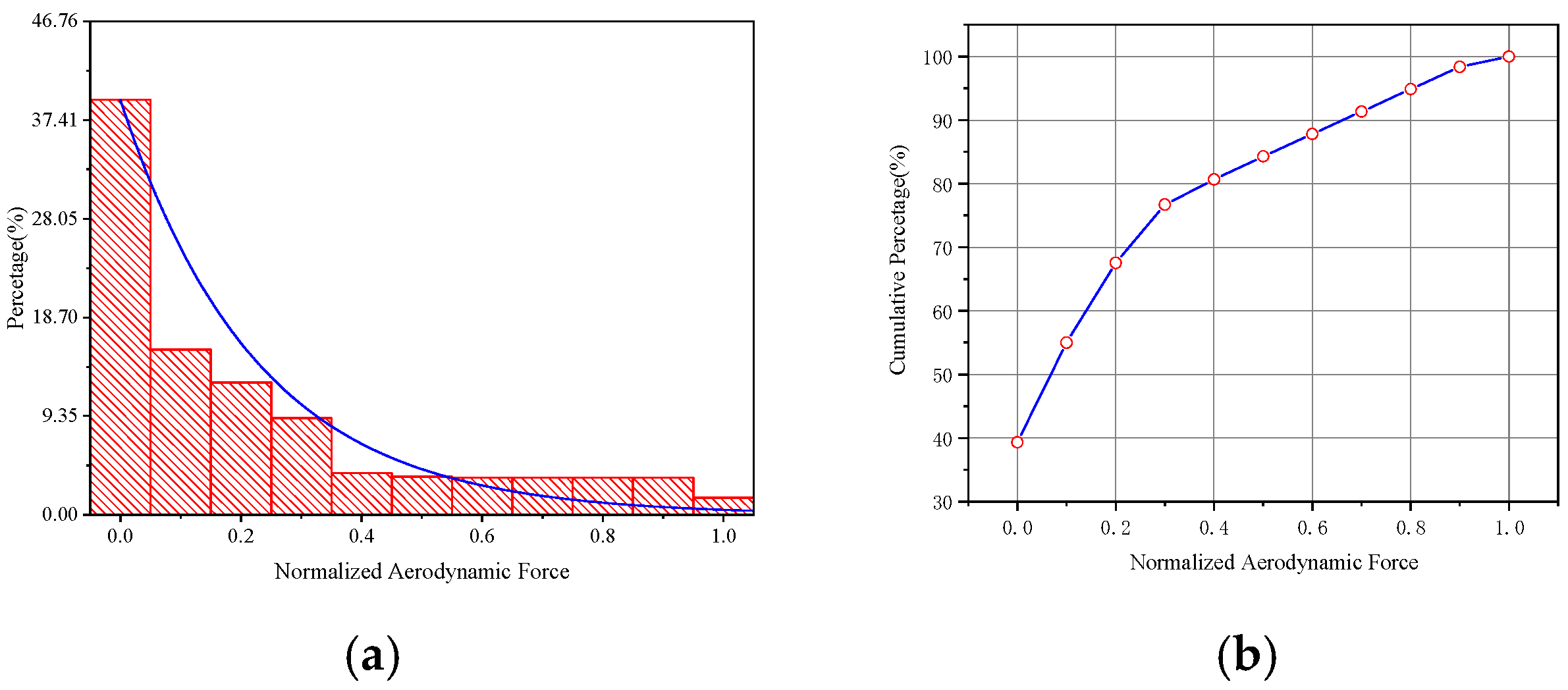
- The aerodynamic force of the helicopter rotor presents a negative exponential distribution, and the values are concentrated between 0 and 0.4;
- (4)
- The main component of aerodynamic force is smaller load, which accounts for nearly 90%.
Author Contributions
Funding
Institutional Review Board Statement
Informed Consent Statement
Data Availability Statement
Acknowledgments
Conflicts of Interest
References
- Sun, Z.Z. Helicopter Strength Specifications; Aviation Industry Press: Beijing, China, 2011; p. 77. [Google Scholar]
- Cong, J.Q.; Jing, J.P.; Chen, C.G.; Dai, Z.Z. Development of a PVDF sensor array for measurement of the dynamic pressure field of the blade tip in an axial flow compressor. Sensors 2019, 19, 1404. [Google Scholar] [CrossRef] [PubMed]
- Zhang, X.G. Helicopter Dynamics Design; Aviation Industry Press: Beijing, China, 1995; pp. 18–32. [Google Scholar]
- Liu, S.S. A survey of rotor load analysis in the UK. J. Nanjing Univ. Aeronaut. Astronaut. 1990, 22, 96–104. [Google Scholar]
- Cumbo, R.; Tamarozzi, T.; Jiranek, P.; Desmet, W.; Masarati, P. State and force estimation on a rotating helicopter blade through a kalman-based approach. Sensors 2020, 20, 4196. [Google Scholar] [CrossRef] [PubMed]
- Daughaday, H.; Kline, J. An Approach to the Determination of Higher Harmonic Blade Stresses; Springer: Boston, MA, USA, 1953; p. 52. [Google Scholar]
- Loewy, R.G.; Sternfeld, J.H.; Spencer, R.H. Evaluation of Rotor Blade Generalized Forces as Determined from Flight Strain Data; WADD Technical Report; 1960; pp. 24–59. [Google Scholar]
- Scheiman, J. A Tabulation of Helicopter Rotor-Blade Differential Pressures, Stresses, and Motions as Measured in Flight; National Aeronautics and Space Administration: Washington, DC, USA, 1964. [Google Scholar]
- DuWaldt, F.A.; Statler, I.C. Derivation of Rotor Blade Generalized Air Loads from Measured Flapwise Bending Moment and Measured Pressure Distributions; Cornell Aeronautical Laboratory: Buffalo, NY, USA, 1966. [Google Scholar]
- Bartlett, F.D.; Flannelly, W.D. Modal Verification of Force Determination For Measuring Vibration Loads. J. Am. Helicopter Soc. 1979, 19, 10–18. [Google Scholar] [CrossRef]
- Giansante, N.; Jones, R.; Calapodas, N.J. Determination of In-Flight Helicopter Loads. J. Am. Helicopter Soc. 1982, 27, 58–64. [Google Scholar] [CrossRef]
- Zhang, J.H.; Li, W.X. Six-Force-Factor Identification of Helicopters. Acta Aeronaut. Astronaut. Sin. 1986, 7, 139–146. [Google Scholar]
- Bousman, W.G. Estimation of Blade Airloads from Rotor Blade Bending Moments. In Proceedings of the 13th European Rotorcraft Forum, Arles, France, 8–11 September 1987. [Google Scholar]
- Liu, S.S.; Davies, G.A.O. The Determination of Rotor Blade Loading from Measured Strains. In Proceedings of the 13th European Rotorcraft Forum, Arles, France, 8–11 September 1987; Available online: http://hdl.handle.net/20.500.11881/2837 (accessed on 1 July 2016).
- Liu, S.S.; Li, N.H. A Technology for Determining Rotor Blade Load. Aerodyn. Exp. Meas. Control 1991, 5, 46–52. [Google Scholar]
- Liu, S.S.; Jerry, P.H.; Daniel, P.S. On the Determination of Helicopter Loads. In Proceedings of the American Helicopter Society Specialist Conference, San Francisco, CA, USA, 19–21 January 1994. [Google Scholar]
- Liu, S.S.; Jerry, P.H.; Daniel, P.S. Coupled Flap-Lag Rotor Blade Load Identification. In Proceedings of the American Helicopter Society 51st Annual Forum, Fort Worth, TX, USA, 9–11 May 1995; pp. 1799–1807. [Google Scholar]
- Jerry, P.H.; Liu, S.S.; Daniel, P.S. Inflow and Load Identification of A Coupled Flap-Lag-Torsion Rotor Blade. In Proceedings of the Twenty Second European Rotorcraft Forum, Brighton, UK, 17–19 September 1996; Available online: http://hdl.handle.net/20.500.11881/3207 (accessed on 13 March 2025).
- Jerry, P.H. Rotor Blade Torsional Load Identification; Kawada: Hiroshima, Japan, 1997; Volume 16, pp. 76–81. [Google Scholar]
- Liu, S.S.; Jerry, P.H.; Daniel, P.S. Approaches for Improving Rotor Load Identification Technology. In Proceedings of the American Helicopter Society 56th Annual Forum, Virginia Beach, VA, USA, 2–4 May 2000; pp. 752–765. [Google Scholar]
- James, S.W.; Kissinger, T.; Weber, S. Dynamic Measurement of Strain and Shape on a Rotating Helicopter Rotor Blade Using Optical Fiber Sensors. In Proceedings of the European Test and Telemetry Conference, Nuremberg, Germany, 23–25 June 2020; pp. 50–53. [Google Scholar]
- Liu, S.S.; Daniel, P.S. Rotor Load and Inflow Determination Technology. In Proceedings of the 2nd International Basic Research Conference Rotorcraft Technology, Nanjing, China, 7–9 November 2005. [Google Scholar]
- Chen, W.; Xia, P.Q. Identification of helicopter rotor blade distributed loads by using fiber optic sensor measurement. J. Vib. Eng. 2009, 22, 183–187. [Google Scholar]
- Sun, Q. Aerodynamic Load Identification of Helicopter Rotor Blade Based on Hybrid Force-Modal Analysis; Nanjing University of Aeronautics and Astronautics: Nanjing, China, 2009. [Google Scholar]
- Simone, W.; Thomas, K.; Edmond, C.H. Application of fibre optic sensing systems to measure rotor blade structural dynamics. Mech. Syst. Signal Process. 2021, 158, 1–17. [Google Scholar] [CrossRef]
- Zhang, H.L. Helicopter Vibration Load Identification Using Inverse Pseudo Excitation Method; Nanjing University of Aeronautics and Astronautics: Nanjing, China, 2011. [Google Scholar]
- Li, Z. Time-Domain Identification of Distributed Dynamic Load on Helicopter Rotor Blade Model; Nanjing University of Aeronautics and Astronautics: Nanjing, China, 2014. [Google Scholar]
- Chen, G.J. Identification of Distributed Dynamic Load on Helicopter Rotor Blade Models Based on Frequency-Domain Method; Nanjing University of Aeronautics and Astronautics: Nanjing, China, 2014. [Google Scholar]
- Zhang, H.L.; Wang, Z.F.; Teng, F.; Xia, P.Q. Dynamic strain measurement of rotor blades in helicopter flight using fiber bragg grating sensor. Sensors 2023, 23, 6692. [Google Scholar] [CrossRef] [PubMed]
- Meng, W.; Pal, A.; Bachilo, S.M.; Weisman, R.B.; Nagarajaiah, S. Next-generation 2D optical strain mapping with strain-sensing smart skin compared to digital image correlation. Sci. Rep. 2022, 12, 11226. [Google Scholar] [CrossRef] [PubMed]


| Type | Resistance/(Ω) | Sensitivity Coefficient |
|---|---|---|
| Resistance Strain Gauge BA350-2AA(9)-G150-JQC | 349.9 ± 0.2 | 2.12 ± 0.01 |
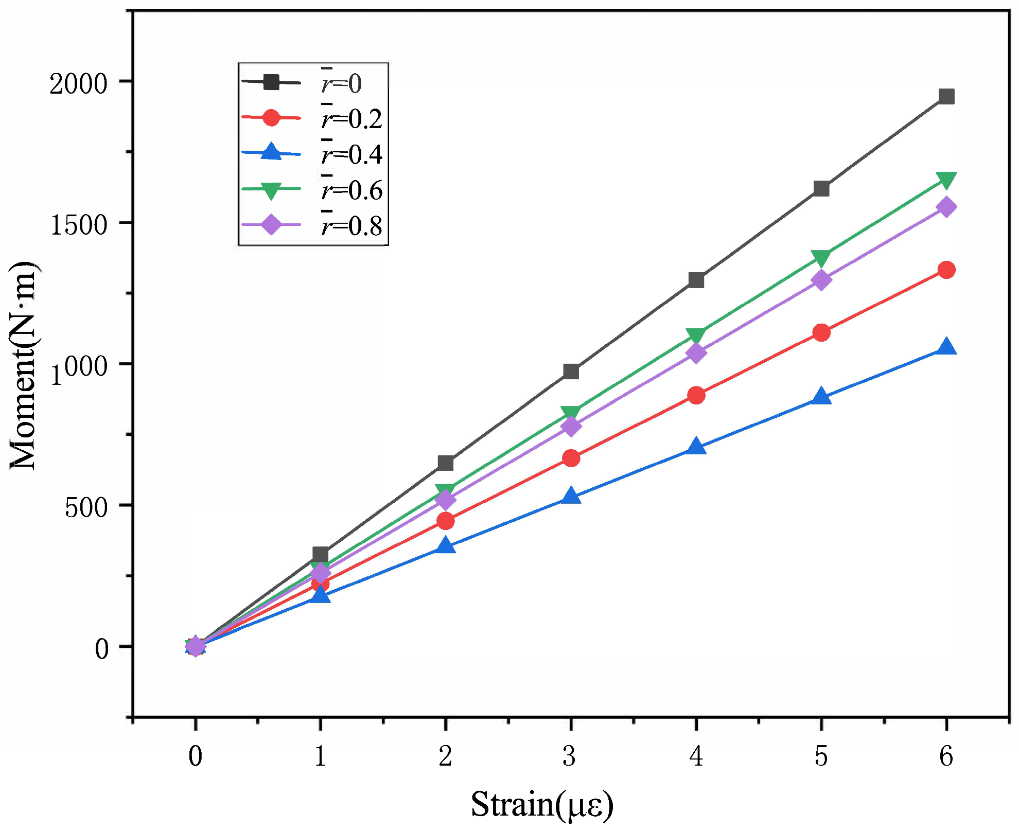
| Section | Curves (x (mV/V), y (N·m)) |
|---|---|
| 0 | y = 324.22x − 0.1107 |
| 0.2 | y = 222.14x − 0.1302 |
| 0.4 | y = 175.72x − 0.1332 |
| 0.6 | y = 276.07x − 0.0222 |
| 0.8 | y = 259.3x + 0.0322 |
Disclaimer/Publisher’s Note: The statements, opinions and data contained in all publications are solely those of the individual author(s) and contributor(s) and not of MDPI and/or the editor(s). MDPI and/or the editor(s) disclaim responsibility for any injury to people or property resulting from any ideas, methods, instructions or products referred to in the content. |
© 2025 by the authors. Licensee MDPI, Basel, Switzerland. This article is an open access article distributed under the terms and conditions of the Creative Commons Attribution (CC BY) license (https://creativecommons.org/licenses/by/4.0/).
Share and Cite
Jiao, S.; Zheng, J. Aerodynamics Analysis of Helicopter Rotor in Flight Test Using Strain Gauge Sensors. Sensors 2025, 25, 1911. https://doi.org/10.3390/s25061911
Jiao S, Zheng J. Aerodynamics Analysis of Helicopter Rotor in Flight Test Using Strain Gauge Sensors. Sensors. 2025; 25(6):1911. https://doi.org/10.3390/s25061911
Chicago/Turabian StyleJiao, Shuaike, and Jiahong Zheng. 2025. "Aerodynamics Analysis of Helicopter Rotor in Flight Test Using Strain Gauge Sensors" Sensors 25, no. 6: 1911. https://doi.org/10.3390/s25061911
APA StyleJiao, S., & Zheng, J. (2025). Aerodynamics Analysis of Helicopter Rotor in Flight Test Using Strain Gauge Sensors. Sensors, 25(6), 1911. https://doi.org/10.3390/s25061911