1. Introduction
Permanent magnet synchronous motors (PMSMs) are widely used in high-reliability applications such as aerospace and precision manufacturing due to their significant advantages, including high efficiency and high-power density [
1,
2,
3,
4]. However, under harsh conditions—such as extreme temperatures and strong vibrations—the likelihood of faults occurring in various motor system components increases, with position sensor faults being among the most common [
5,
6,
7]. As a critical element of the motor control system, the position signal directly influences key control algorithms, including coordinate transformations. Sensor faults can cause a severe decline in system performance or even complete failure, posing a serious threat to high-reliability applications.
Current position sensor fault diagnosis methods are primarily categorized into two technical approaches: hardware redundancy and analytical redundancy [
8]. Hardware redundancy enhances system reliability by incorporating backup sensors; however, it increases system size, cost, and complexity, making it challenging to meet the requirements for lightweight design and high integration. Conversely, analytical redundancy methods generate redundant information by establishing mathematical models of the system without the need for additional hardware, gradually becoming the mainstream in research. These methods include signal-based, model-based, and knowledge-based approaches [
9], with model-based methods offering a slight advantage in designing fault-tolerant control strategies. Nevertheless, existing methods still require improvements in adaptability to dynamic operating conditions, multi-fault handling capabilities, and engineering implementation complexity, underscoring the urgent need to develop more advanced and flexible fault diagnosis and fault-tolerant control technologies.
In recent years, numerous scholars have conducted in-depth research on fault diagnosis and fault-tolerant control of PMSM position sensors. Reference [
10] proposes a diagnosis and fault-tolerant control method by analyzing the impact of current and position sensor faults on system performance; however, its diagnostic accuracy is relatively low in low-speed regions. Reference [
11] achieves fault identification by utilizing the relationship between sensor detection signals and induced current; nevertheless, it relies on a dual-sensor configuration, resulting in increased system complexity and limited stability. Reference [
12] indirectly diagnoses position faults based on rotor internal resistance and estimated current but does not propose a corresponding fault-tolerant control scheme. Reference [
13] presents an integrated method of fault detection, reconstruction, and fault-tolerant control based on sliding mode control, enabling real-time fault handling; however, its robustness and computational efficiency in multi-fault coupling scenarios require improvement. Reference [
14] combines generalized likelihood ratio testing with structural analysis to achieve highly sensitive early detection of inter-turn short circuits and sensor faults, but it strongly depends on model accuracy, and its reliability under strong noise conditions requires further verification. Reference [
15] proposes a static fault diagnosis method based on current estimation, identifying offset faults through current residuals; it demonstrates good robustness at low speeds but exhibits weak adaptability to parameter variations and load disturbances. Reference [
16] employs a high-frequency injection method for zero and low-speed conditions, estimating rotor position through high-frequency response and maintaining 90% of rated torque at 5 rpm; however, it introduces additional copper losses and electromagnetic interference and demands a high inverter switching frequency.
To enhance estimation accuracy and control performance, various advanced observers have been developed. Reference [
17] employs an Active Disturbance Rejection Controller (ADRC) to replace the traditional sliding mode observer. It estimates the rotor position using an extended back electromotive force (EMF) model and extracts speed and position signals through a phase-locked loop (PLL). This approach effectively mitigates the chattering and lag issues associated with sliding mode observers, thereby improving steady-state performance; however, its robustness against variations in permanent magnet parameters remains to be verified. Reference [
18] proposes a sensorless fault-tolerant control method based on a back-EMF observer, enabling continuous system operation following sensor failure. Experimental results demonstrate its effectiveness in steady-state conditions but reveal significant position estimation errors at low speeds or during transient processes. Reference [
19] designs a robust state observer to achieve real-time detection and isolation of position and current sensor faults, ensuring stable system operation after faults occur. Nevertheless, under high dynamic loads, the observer’s convergence speed is relatively slow, which adversely affects transient response.
In the field of signal processing and model reconstruction, reference [
20] proposes a sensorless fault-tolerant control scheme for PMSMs based on the separation of positive and negative sequence components. It employs zero-crossing detection and rotating coordinate system component extraction to achieve fault monitoring and position reconstruction. Experimental results validate its effectiveness; however, the real-time performance of the algorithm under high-speed or sudden load changes was not evaluated. Reference [
21] develops fault feature quantities based on the input/output power relationship to enable online detection of sensor deflection faults and estimation of error angles. This method is suitable for the vibration environment of electric vehicles but relies on power calculations, which may reduce detection sensitivity under low-load conditions. Reference [
22] presents a sensorless fault-tolerant strategy based on current space vector error reconstruction. When encoder faults occur, the rotor position is estimated through current error, enabling smooth switching. However, this approach is sensitive to current sampling accuracy and system delay, and its performance degrades under low signal-to-noise ratio conditions.
To further optimize the fault-tolerant process, reference [
23] employs a vector tracking observer to achieve fault tolerance for Hall sensors. During faults, the system switches to an open-loop observer to suppress current surges, supporting dual Hall sensor fault handling and significantly improving transient performance. However, open-loop operation may lead to short-term accumulation of estimation errors. Reference [
24] proposes a rapid fault diagnosis method based on a pseudo-acceleration change threshold, combined with an improved fault-tolerant interpolation method and an adaptive notch angle observer. This approach effectively addresses diagnostic delays and control accuracy degradation caused by installation deviations in permanent magnet synchronous motor (PMSM) Hall position sensor faults but does not consider complete sensor failure scenarios without position feedback control strategies. Reference [
25] detects faults by analyzing the relationship between Hall signal transition edges and system states and reconstructs position information through harmonic analysis. It supports fault tolerance for single or dual Hall sensor failures, maintaining good system performance; however, the computational burden is relatively high, limiting its application in high-frequency scenarios. Reference [
26] addresses open-circuit faults in five-phase PMSMs by combining sliding mode control with a nonlinear extended state observer (NESO), significantly suppressing torque fluctuations, but does not cover other fault types such as inter-phase short circuits.
Building upon previous research, this paper addresses the vulnerability of position sensors in permanent magnet synchronous motors (PMSMs) within electromechanical actuation systems to failures under complex operating conditions. It proposes an integrated fault diagnosis and fault-tolerant control method based on the Cubature Kalman Filter (CKF). The objective is to enable precise identification of multiple typical and compound faults while ensuring stable system operation under fault conditions. The main research questions addressed in this paper include: (1) How to establish a unified mathematical model encompassing both basic and compound fault types; (2) how to achieve high-precision and robust reconstruction of motor states; (3) how to design a diagnostic mechanism capable of distinguishing among multiple fault modes; and (4) how to ensure the effectiveness of the fault-tolerant control strategy under various disturbance conditions. The key innovations of this work are as follows: (1) A comprehensive fault model is constructed, covering signal disconnection, signal stalling, signal offset, intermittent disconnection, and coupled disconnection-offset faults—capturing the full spectrum of anomalies commonly encountered in practical engineering scenarios. (2) A CKF-based state reconstruction method utilizing innovation and residual sequences is proposed, enabling highly accurate and robust estimation of rotor position and speed. (3) A dual-parameter threshold-based fault diagnosis mechanism is designed, which not only effectively identifies and differentiates multiple fault patterns but also synchronously triggers a robust fault-tolerant control strategy. The reliability and adaptability of the proposed method are validated through simulations under multiple disturbance scenarios. The remainder of this paper is organized as follows:
Section 2 summarizes typical fault types of position sensors, establishes a unified mathematical model, and analyzes the impact of these faults on key motor state variables.
Section 3 presents the CKF-based state reconstruction approach, accompanied by Lyapunov stability analysis and computational complexity evaluation.
Section 4 details the design of the fault diagnosis mechanism and fault-tolerant control strategy, followed by simulation verification and robustness analysis.
Section 5 concludes the paper with a summary and outlook.
4. Position Sensor Fault Diagnosis and Fault-Tolerant Control
Permanent magnet synchronous motors in electromechanical actuator systems typically operate within the medium to high-speed range at rated speeds. Consequently, the likelihood of position sensor failure during zero or low-speed startup is relatively low. This paper primarily focuses on the study of position sensor faults occurring during the medium to high-speed operation phase of permanent magnet synchronous motors used in electromechanical actuators.
4.1. Fault Diagnosis and Fault-Tolerant Strategies
This paper introduces a dual-threshold diagnostic mechanism that utilizes position residuals and signal anomaly duration thresholds within the fault diagnosis logic. This approach effectively mitigates misjudgments and missed detections commonly caused by traditional methods relying on a single reference value, which is susceptible to noise and parameter perturbations. As a result, it significantly enhances the robustness of the diagnostic strategy. The diagnostic logic for individual single faults is illustrated in
Figure 2 and
Table 3. Because complex faults consist of combinations of single faults, separate diagnostic logic for complex faults has not been established.
Using the absolute value of the position signal, |θe|, to diagnose disconnection faults in the position signal. When a fault occurs, the position signal rapidly drops and remains at zero. To prevent false alarms, an abnormal time parameter, Tthreshold, should be incorporated. During the fault period ΔT, if the absolute value of the position signal |θe| equals zero and ΔT is greater than or equal to Tthreshold, it can be concluded that the position sensor has a signal disconnection fault, and the fault diagnosis flag is set to a high level.
Using the rate of change in the position signal, dθe/dt, to diagnose position signal stalling faults: when a fault occurs, the sensor output signal remains fixed at the value present at the time of the fault and no longer changes. By monitoring whether dθe/dt equals zero and incorporating an abnormal time threshold, Tthreshold, to prevent false alarms, it can be determined that a position sensor signal stalling fault has occurred if, during the fault duration ΔT, the rate of change continuously remains zero and ΔT ≥ Tthreshold. In this case, the fault diagnosis flag is set to a high level.
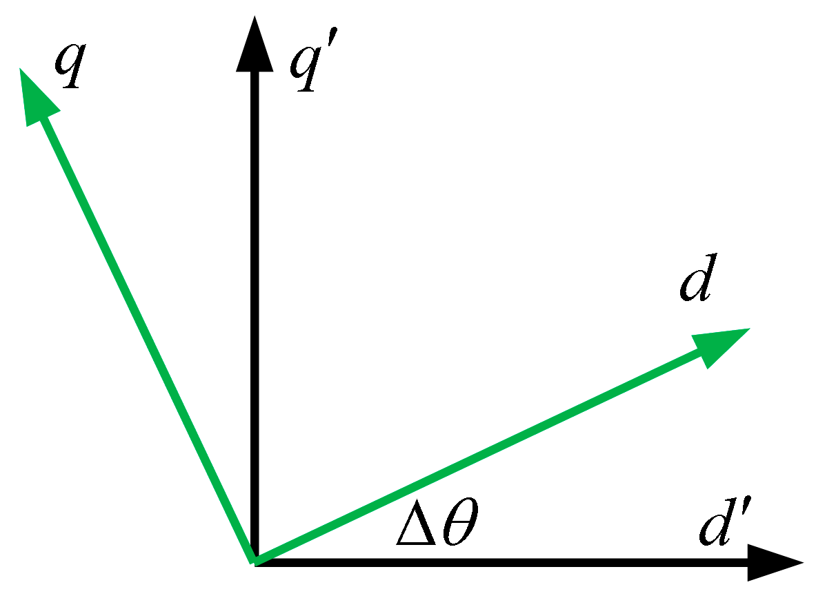
Using the position signal residual Δθ to diagnose position signal shift faults. When the system maintains Δθ < θthreshold, it indicates that the position sensor is functioning normally. A typical characteristic of a signal shift fault is a constant difference between the rotor’s actual position and the position measured by the sensor, with this difference exceeding the threshold θthreshold. Since the position signal crosses zero once every rotation cycle, an abnormal time parameter threshold, Tthreshold, is introduced to prevent false detections. A shift fault can only be confirmed when, during the fault period t > Ton, the measured position error exceeds the position residual threshold θthreshold and the duration ΔT ≥ Tthreshold. At this point, the fault diagnosis flag is set to a high level.
As shown in
Figure 3, the output of the fault-tolerant control module is governed by the fault flag signal. Its inputs include the position and speed values detected by the sensor, as well as the position and speed values reconstructed through the volumetric Kalman filter. When the position sensor is functioning normally, the fault flag signal is low. In this state, the fault-tolerant control module uses the sensor-detected values for the motor’s vector control. However, when the fault detection module sets the fault flag signal high, the fault-tolerant control module switches to fault-tolerant mode, using the CKF-reconstructed values for vector control to ensure stable motor operation.
4.2. Simulation Verification
A simulation model was developed in the MATLAB/Simulink (2023b) environment to validate the proposed fault diagnosis and fault-tolerant control strategy. Within the standard Field-Oriented Control (FOC) framework, the outer speed loop controller utilizes three alternatives: conventional PI control, Sliding Mode Control (SMC), and an Improved Sliding Mode Control (ISMC). The inner current loop employs a PI controller. The simulation uses a fixed-step oed3 solver with a sampling frequency of 10 kHz and a total simulation duration of 0.5 s. The position signal fault detection threshold is set to 10°, and the abnormal duration threshold is 0.2 s.
Table 4 lists the relevant parameters of the PMSM, while
Table 5 presents the controller parameters.
4.2.1. Performance Analysis of State Reconstruction Under Normal Operating Conditions
When the position sensor operates normally, the system simultaneously runs the Adaptive Cubature Kalman Filter (ACKF) with adaptive parameters, the standard Cubature Kalman Filter (CKF) with fixed parameters, and the Extended Kalman Filter (EKF) with fixed parameters to reconstruct the rotor position state. This approach aims to pre-evaluate the performance of each algorithm and select the optimal backup algorithm for seamless switching in the event of a fault.
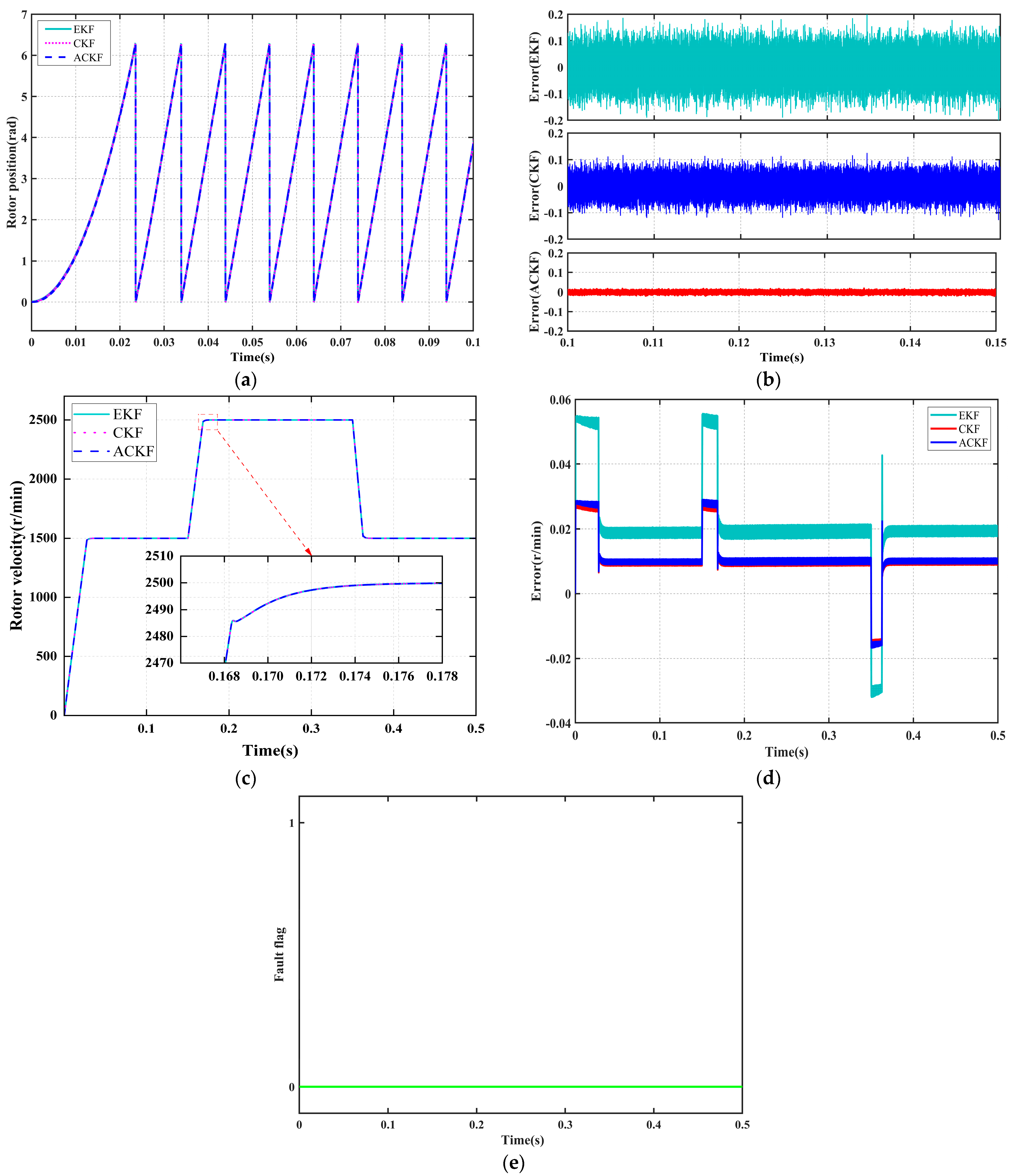
Figure 4 illustrates the reconstructed trajectories and error characteristics of the three algorithms.
Figure 4a displays the time-domain response curves of the measured rotor position values alongside the reconstructed values from each filter, while
Figure 4c presents the corresponding reconstruction results for rotor speed. As shown in
Figure 4b,d, the position reconstruction errors for all three filtering algorithms remain within ±0.2 rad, and the speed reconstruction errors are within 1 r/min. Notably, the ACKF demonstrates the smallest error magnitude and the least fluctuation, indicating superior tracking stability. Furthermore, as depicted in
Figure 4e, the introduction of a dual-criterion mechanism combining a time delay threshold with a position residual threshold enables the system to effectively suppress false alarms caused by filter tracking delays or transient disturbances during normal operation.
For a more comprehensive quantitative comparison,
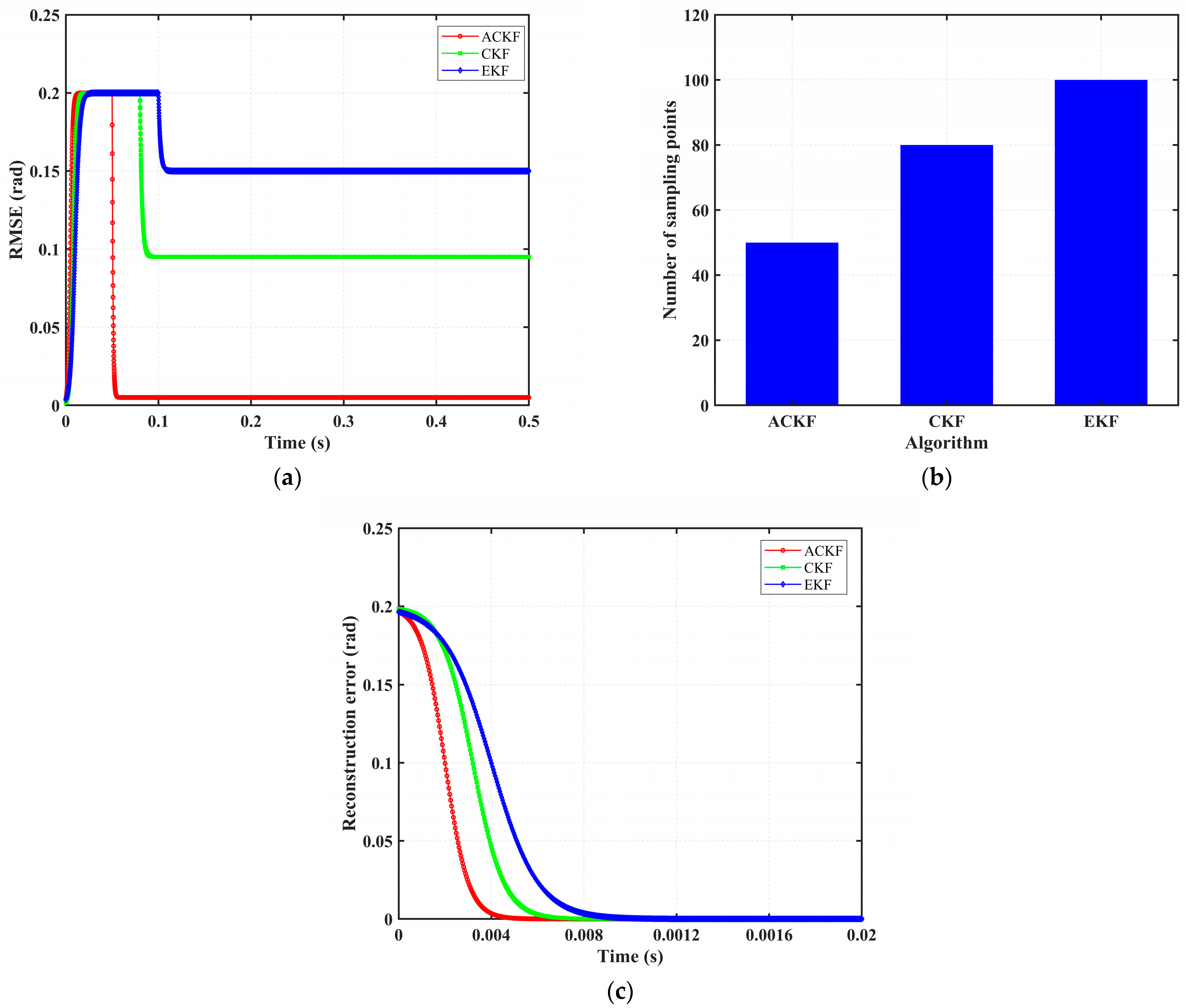
Figure 5 systematically evaluates performance across three dimensions: state estimation accuracy, computational efficiency, and convergence speed. The corresponding data are summarized in
Table 6. As illustrated in both the figure and the table, the ACKF outperforms other state reconstruction algorithms by achieving the highest estimation accuracy, greatest computational efficiency, and fastest convergence speed, thereby demonstrating significant advantages in all evaluated aspects.
Based on the above analysis, this paper selects the ACKF algorithm as the backup reconstruction method for position sensor faults, ensuring seamless and high-precision state recovery in the following five fault scenarios.
4.2.2. Signal Disconnection Fault
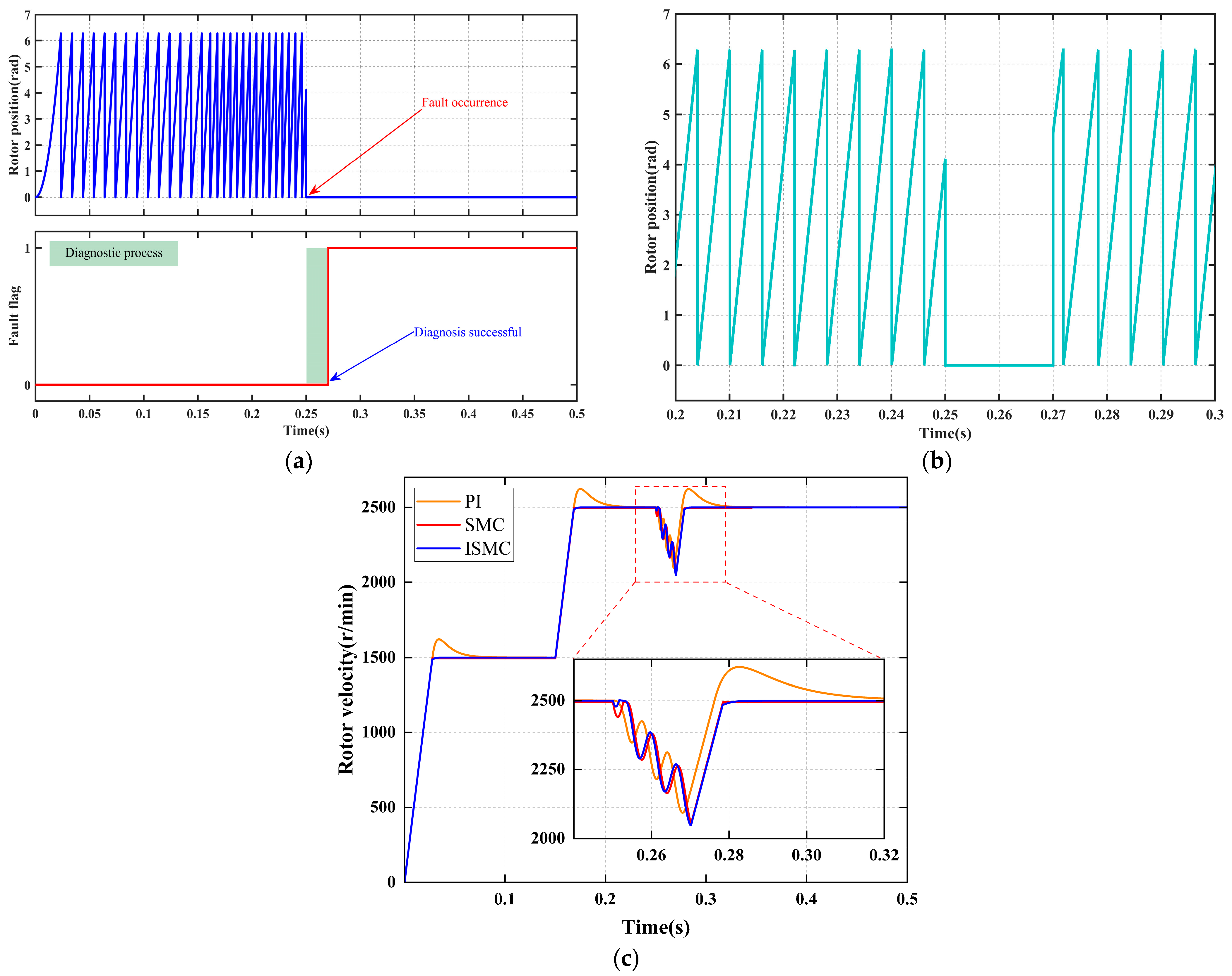
Figure 6 systematically illustrates the collaborative response performance of the fault diagnosis mechanism and the fault-tolerant control strategy under a “position signal disconnection fault. As shown in
Figure 6a, at 0.25 s, a position sensor signal disconnection fault occurs, causing the sensor output to instantly drop to zero. Upon real-time detection of this abnormal signal by the fault diagnosis module, a signal anomaly duration detection mechanism is immediately activated. When the anomaly duration exceeds the preset threshold, the system sets the fault flag signal to a logic high “1” at 0.27 s, thereby accurately diagnosing the position sensor signal disconnection fault.
As shown in
Figure 6b, once the fault flag signal is set at 0.27 s, the position signal seamlessly switches to the reconstructed value derived from the faulty position sensor signal, without any disturbance. At this point, the system transitions to a fault-tolerant operation mode, ensuring continuous and stable operation.
Figure 6c and
Table 7 present the dynamic response characteristics under the fault-tolerant operation mode. The diagnostic system achieves an ultra-fast fault detection response time of 20 ms, while state reconstruction ensures continuous control. Although the ISMC strategy experiences the largest speed drop, it achieves non-overshoot and zero steady-state error control within the shortest recovery time of 0.03 s, demonstrating the best overall dynamic performance.
4.2.3. Signal Stagnation Faults
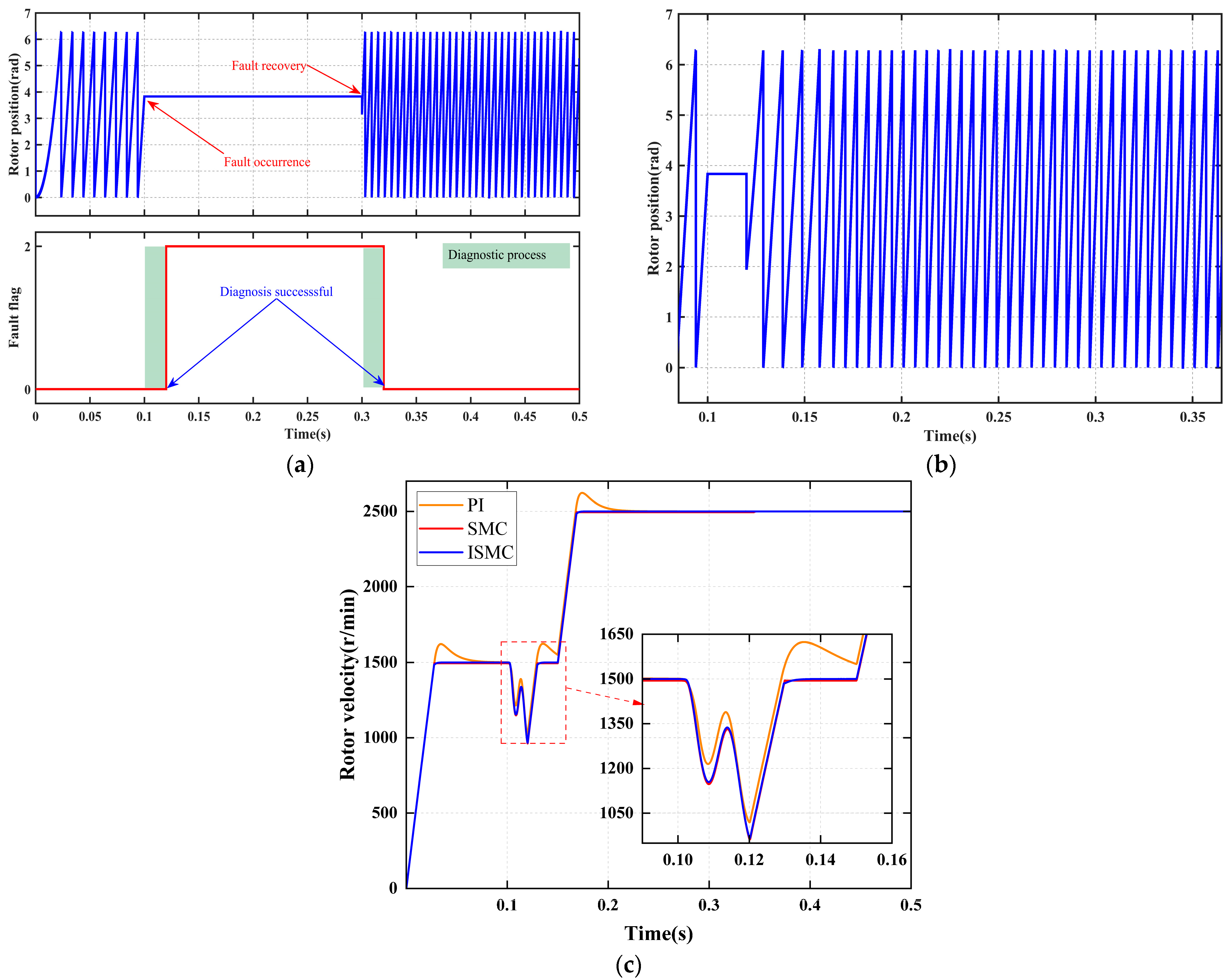
Figure 7 systematically illustrates the coordinated response performance of the fault diagnosis mechanism and fault-tolerant control strategy under the stall fault condition. The fault occurs at 0.1 s, and the system completes diagnosis and achieves smooth switching of the position signal by 0.12 s. Subsequently, the three control strategies, PI, SMC, and ISMC, demonstrate significant differences in dynamic speed recovery, comprehensively validating the effectiveness of the fault diagnosis and fault-tolerant control strategies in scenarios involving sensor signal stagnation.
Figure 7a demonstrates that the diagnostic module accurately detects signal stall characteristics within 20 ms of fault occurrence and promptly outputs the fault flag, thereby satisfying the functional safety requirement for millisecond-level diagnostic response.
Figure 7b shows that immediately following diagnostic confirmation, the reconstruction algorithm activates, enabling a smooth, shock-free transition from the measured signal to the estimated trajectory, thus ensuring continuity of the control layer inputs.
Figure 7c and
Table 8 quantitatively illustrate the following: under PI control, the speed drops by 478 r/min, recovers in 0.052 s, and exhibits an overshoot of 124 r/min, revealing its weak disturbance rejection and integral windup limitations; under SMC control, the speed drops by 538 r/min, recovers in 0.13 s with no overshoot but leaves a steady-state error of 4 r/min, indicating insufficient compensation for model mismatch; under ISMC control, the speed drops by 530 r/min, recovers in 0.13 s, and shows neither overshoot nor steady-state error, highlighting its strong robustness and effective compensation against state stall faults.
4.2.4. Signal Offset Fault
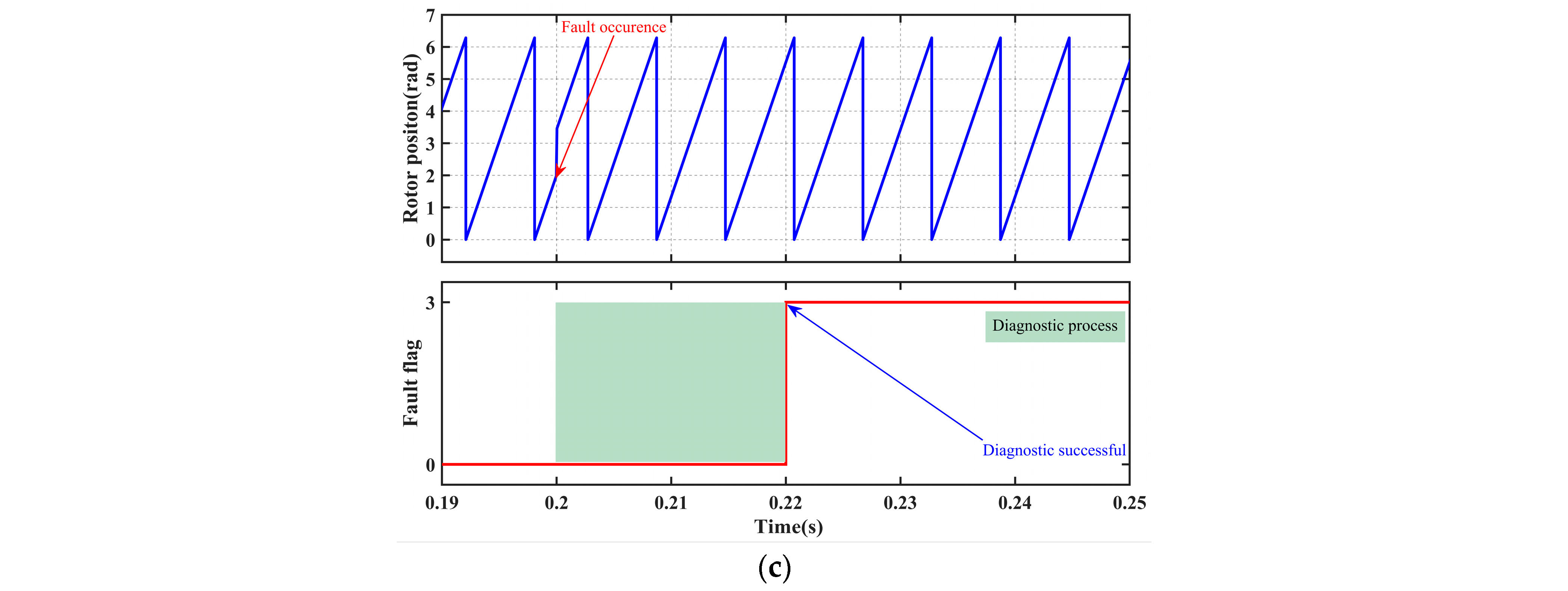
Figure 8 systematically illustrates the coordinated response performance of the fault diagnosis mechanism and fault-tolerant control strategy under the “signal offset fault” condition. The fault occurs at 0.2 s, and the system completes diagnosis and achieves smooth switching of the position signal by 0.22 s. Subsequently, the three control strategies, PI, SMC, and ISMC, exhibit significant differences in dynamic speed recovery, comprehensively validating the effectiveness and superiority of the fault diagnosis and fault-tolerant control strategies in scenarios involving position sensor offset disturbances.
As shown in
Figure 8a, the diagnostic module accurately identifies the offset characteristics and outputs a stable flag within 20 ms, thereby meeting the functional safety requirement for millisecond-level response. As illustrated in
Figure 8b, the reconstruction algorithm simultaneously achieves a shock-free transition from measured values to estimated values, ensuring continuous control input.
Figure 8c and
Table 9 present the speed response data. Under PI control, the speed decreases by 22 r/min, takes 0.05 s to recover, and exhibits an overshoot of 23 r/min, indicating weak disturbance rejection and integral windup issues. Under SMC control, there is no overshoot, and the recovery time is 0.02 s; however, a steady-state error of 6 r/min remains, reflecting insufficient compensation for systemic bias. Under ISMC control, the system also recovers in 0.02 s, with neither overshoot nor steady-state error, demonstrating its precise compensatory capability for offset disturbances through adaptive mechanisms.
4.2.5. Signal Disconnection-Recovery Loop Fault
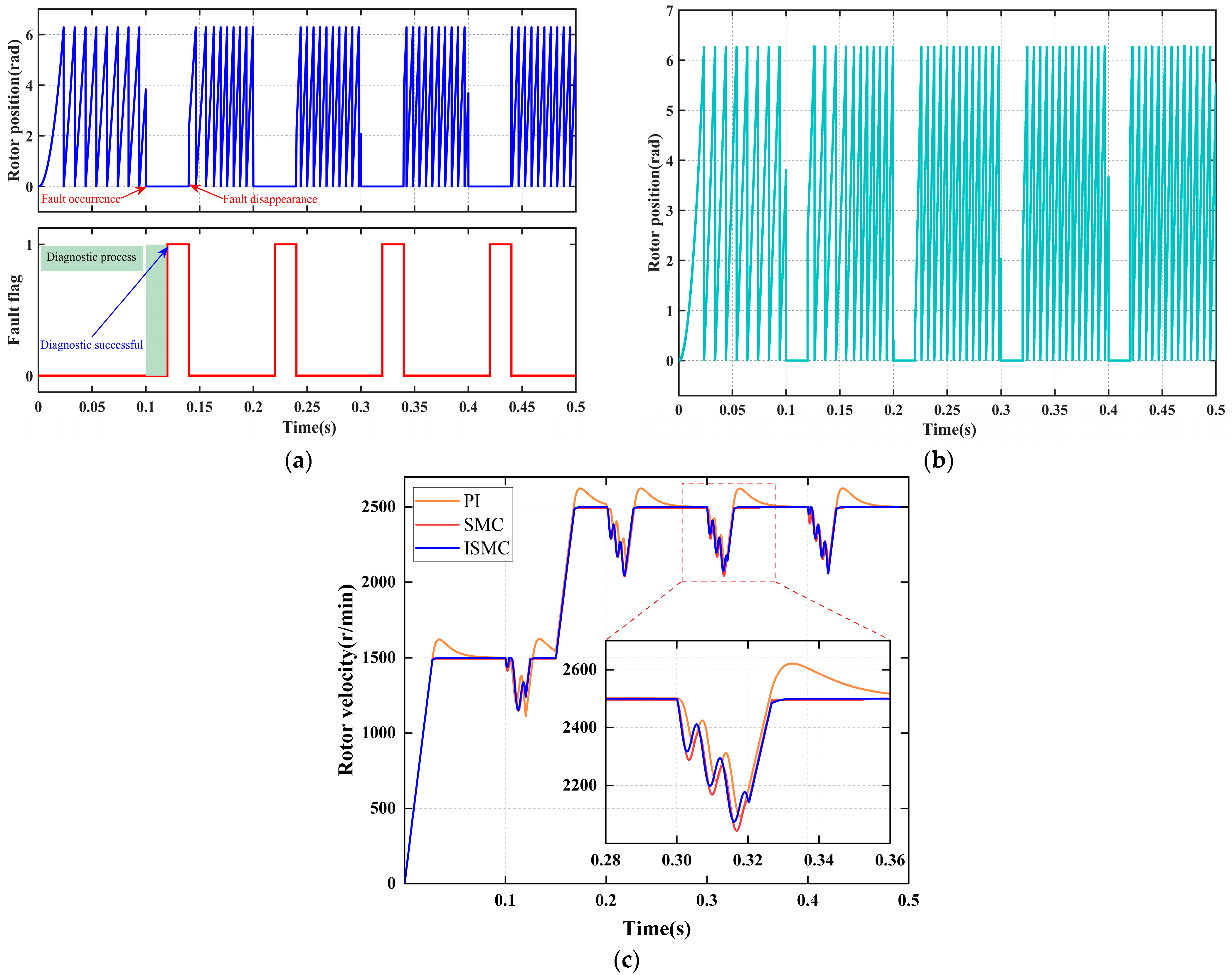
Figure 9 systematically illustrates the coordinated response performance of the fault diagnosis mechanism and fault-tolerant control strategy under the “signal intermittent disconnection-recovery loop fault” condition. The first fault occurs at 0.15 s, and the system completes diagnosis within 0.02 s; subsequent cyclic faults maintain the same response speed. Upon successful diagnosis, the reconstructed signal seamlessly replaces the sensor input, ensuring continuous control. The speed response differences among the PI, SMC, and ISMC strategies during the initial fault event are significant, comprehensively validating the engineering effectiveness of the fault diagnosis and fault-tolerant strategies in scenarios involving intermittent disconnection-recovery loop faults.
As shown in
Figure 9a, the diagnostic module accurately identifies the intermittent signal characteristics and consistently outputs the fault flag within 20 ms, meeting the functional safety requirement for rapid response to repetitive faults. As illustrated in
Figure 9b, the position signal switches immediately to the reconstructed trajectory upon fault confirmation, achieving a smooth, shock-free, and lag-free transition, thereby ensuring uninterrupted input to the control layer.
The speed response data are presented in
Figure 9c and
Table 10. Under PI control, the speed decreases by 405 r/min, takes 0.08 s to recover, and exhibits an overshoot of 121 r/min, indicating weak disturbance rejection capability and integral windup issues. Under SMC control, the speed decreases by 456 r/min, recovers in 0.035 s, and shows no overshoot but leaves a steady-state error of 6 r/min, reflecting steady-state deviation when compensating for high-frequency disturbances. Under ISMC control, the speed decreases by 425 r/min, recovers in 0.03 s, and demonstrates neither overshoot nor steady-state error, highlighting its robust compensation capability for intermittent state loss.
4.2.6. Signal Disconnection-Offset Coupled Fault
Figure 10 systematically illustrates the coordinated response performance of the fault diagnosis mechanism and the fault-tolerant control strategy under the “disconnection-offset coupled fault” condition. The fault evolves in two stages: first, a signal disconnection occurs at 0.1 s, and the system completes the diagnosis by 0.125 s; however, the reconstructed value does not take effect at this point. Second, at 0.25 s, the disconnection is resolved, and a fixed offset is introduced. The system completes the diagnosis by 0.27 s, while the reconstruction algorithm simultaneously compensates for the offset.
As shown in
Figure 10a, the diagnostic module rapidly identifies faults and switches modes within 20 ms in both stages, without any confusion or missed alarms.
Figure 10b illustrates that the reconstruction algorithm maintains trajectory continuity during the disconnection phase and performs online compensation for system bias during the offset phase, ensuring smooth control input throughout.
The speed response data are presented in
Figure 10c and
Table 11. Under PI control, during disconnection, the speed drops by 380 rpm, recovers within 0.05 s, and exhibits an overshoot of 123 rpm. During the offset, the speed drops by 132 r/min and recovers within 0.045 s, exhibiting a 95 r/min overshoot, indicating weak disturbance rejection and integral windup. Under SMC control, the recovery time in both stages is 0.03 s with no overshoot; however, steady-state errors of 5 r/min and 6 r/min persist, respectively, indicating limited compensation capability. Under ISMC control, the smallest speed drop during disconnection was 255 r/min, and during the offset, it was 77 r/min. The system recovers in 0.03 s during both stages, with neither overshoot nor steady-state error, highlighting the robust compensation capability of its adaptive mechanism against coupled disturbances. The PI, SMC, and ISMC strategies exhibit significant differences in both stages, comprehensively validating the engineering effectiveness of diagnosis and fault-tolerant control under coupled fault conditions.
4.3. Robustness Analysis
To comprehensively evaluate the robustness of the proposed fault diagnosis and fault-tolerant control strategy under non-ideal operating conditions, systematic simulation-based robustness tests were conducted, focusing on three typical scenarios: motor parameter uncertainties, dynamic external load disturbances, and measurement noise interference. Additionally, the impact of diagnostic threshold selection on fault detection sensitivity and false alarm rates was analyzed to verify the stability, reliability, and practical applicability of the algorithm under conditions of parameter drift, strong disturbances, and noisy environments. All tests were performed using the MATLAB/Simulink platform.
4.3.1. Parameter Perturbation
Under prolonged operation or temperature fluctuations, key electrical parameters of permanent magnet synchronous motors (PMSMs) may drift to varying degrees, thereby affecting the accuracy of state reconstruction and the reliability of fault diagnosis. To evaluate the robustness of the ACKF reconstruction algorithm and diagnostic logic against such model uncertainties, two parameter perturbation scenarios, as detailed in
Table 12, were designed.
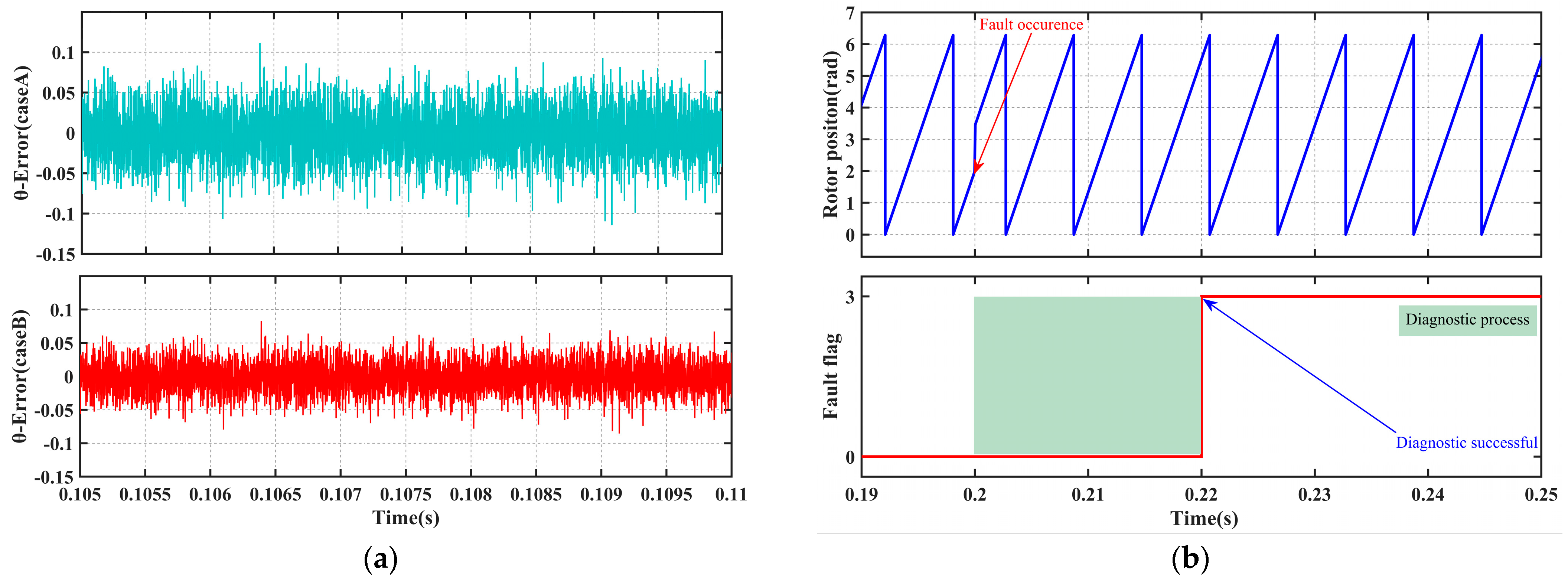
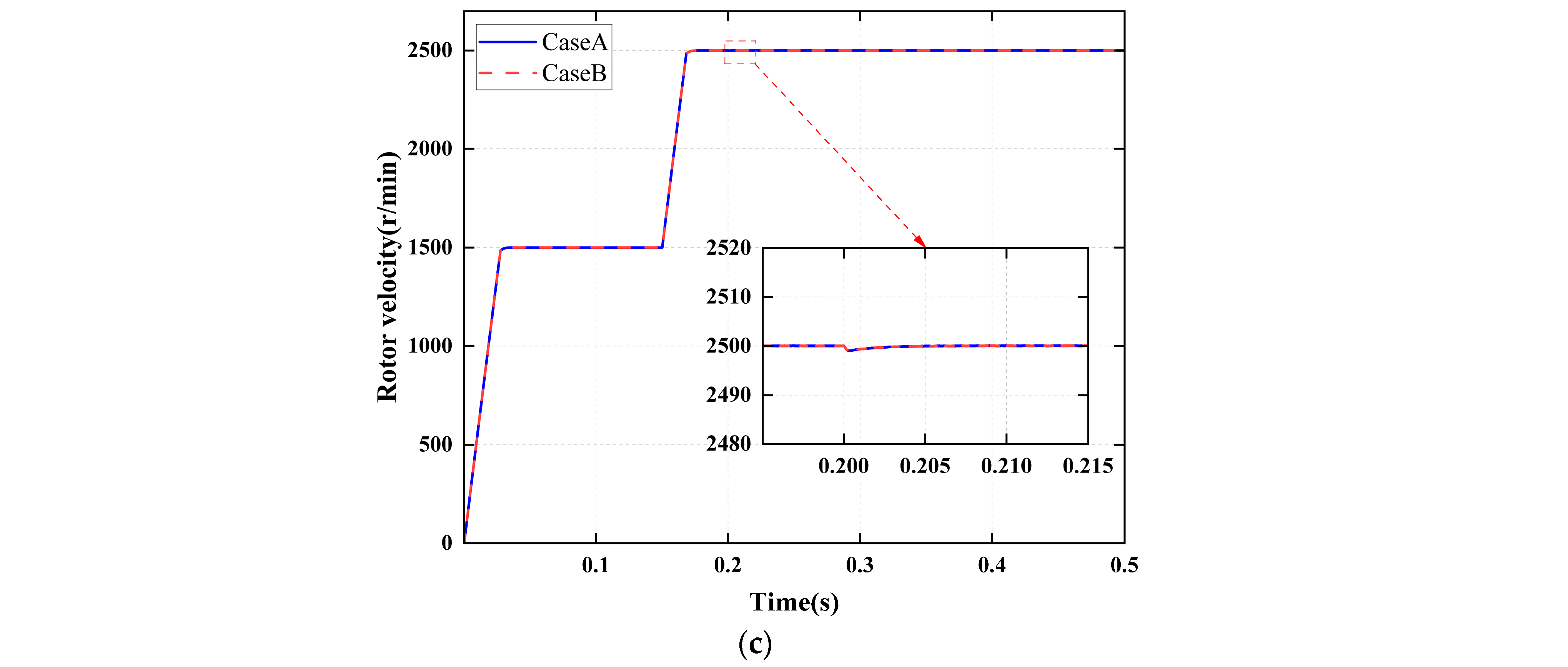
Under both perturbation scenarios, a −30° offset fault in the position sensor is introduced at 0.2 s and persists until the end of the simulation.
Figure 11 illustrates the rotor position reconstruction error and the diagnostic flag response curves under these conditions.
Under the aforementioned parameter perturbation scenarios, the position estimation error of the CKF remains stably within ±0.15 rad, and the fault diagnosis module accurately triggers fault-tolerant switching within the preset time threshold, with no missed or false alarms. This confirms the inherent robustness of the ACKF algorithm against model parameter uncertainties, as well as the strong adaptability of the dual-threshold diagnostic mechanism to parameter drift.
4.3.2. Sudden Load Torque Disturbance
At 0.2 s, a sudden 50% increase in the rated load is applied, rising from 3.5 N·m to 5.25 N·m, accompanied by the introduction of a position sensor offset fault of −30°. As shown in
Figure 12, under the combined disturbances of the sudden load change and the concurrent fault, the speed decreases by a maximum of approximately 50 r/min. However, with the implementation of fault-tolerant control, stability is restored within 20 ms. The fault diagnosis flag is accurately triggered at 0.22 s, indicating that the diagnostic logic remains unaffected by load disturbances, and the fault-tolerant control maintains strong resistance to load impacts.
4.3.3. Measurement Noise Robustness Test
Zero-mean Gaussian white noise with a signal-to-noise ratio (SNR) of 30 dB was added to the α-β axis current measurement signals to simulate real-world sampling conditions. As shown in
Figure 13, although the noise induces slight fluctuations in the position reconstruction error, with a peak-to-peak amplitude of approximately ±0.17 rad, the diagnostic mechanism effectively filters out transient spike interference and prevents false triggering. Consequently, the system maintains stable operation even under noisy conditions.
4.3.4. Threshold Sensitivity Analysis
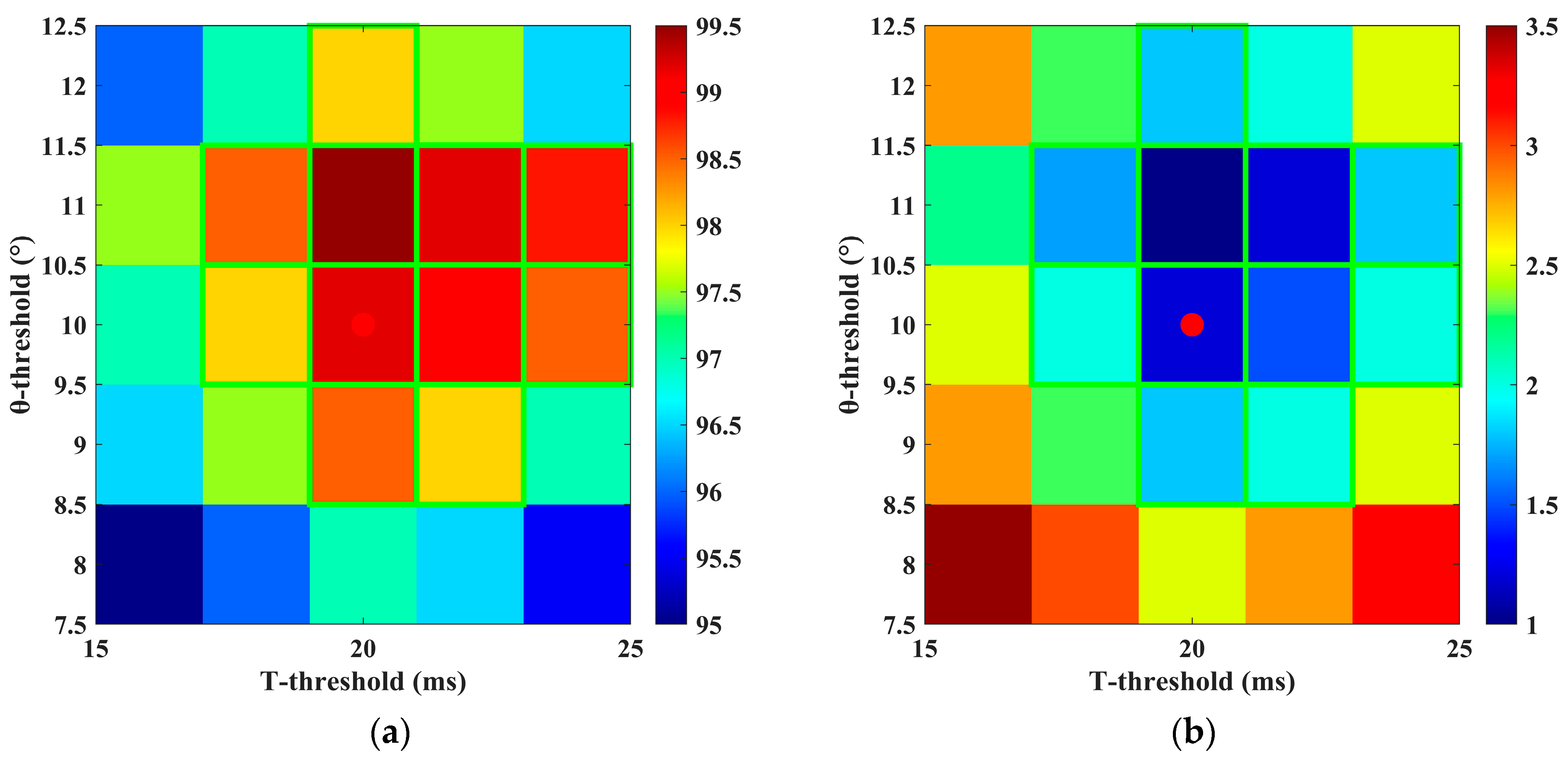
To verify the robustness of the selected dual thresholds, this paper systematically varies both threshold parameters within a ±20% range: the position residual threshold is adjusted from 8° to 12°, and the anomaly duration threshold is adjusted from 16 ms to 24 ms, with step sizes of 1° and 2 ms, respectively. This results in a total of 25 threshold parameter combinations. For each combination, 60 simulation experiments were conducted, covering five typical fault conditions as well as normal operating states, to statistically evaluate the corresponding Detection Accuracy (DA) and False Alarm Rate (FAR).
As shown in
Figure 14, the visual analysis based on the heatmap of diagnostic accuracy (DA) and false alarm rate (FAR) under different threshold combinations indicates that the selected threshold combination (10°, 20 ms) lies within the central region of a “robust plateau” exhibiting excellent performance. With this parameter setting, the system achieves a diagnostic accuracy of 99.2% and a false alarm rate of 1.2%. Further analysis reveals that when both thresholds vary within ±10% of their nominal values, the system maintains high performance, with DA ≥ 98.5% and FAR ≤ 1.5%. These results demonstrate that the selected threshold combination possesses strong robustness and reliability, ensuring efficient and stable system operation under varying working environments and conditions.
5. Conclusions and Future Work
5.1. Conclusions
This paper addresses common position sensor faults in permanent magnet synchronous motors (PMSMs) used in electromechanical actuation systems by developing a unified mathematical model that encompasses multiple fault modes, including signal disconnection, signal stall, static offset, intermittent interruption, and disconnection-offset coupling. From the perspective of the dynamic propagation mechanisms of state variables, the paper systematically elucidates how each fault mode affects the closed-loop control performance of the motor, thereby establishing a theoretical foundation for fault mechanism analysis and the design of fault-tolerant architectures.
Building on this foundation, an improved adaptive cubature Kalman filter (ACKF) algorithm is proposed to achieve high-precision and robust online reconstruction of rotor position and speed under sensor failure conditions. Theoretical analysis demonstrates that the algorithm possesses global asymptotic stability within the Lyapunov framework. Simulation results further confirm that the proposed algorithm significantly outperforms the conventional extended Kalman filter (EKF) in terms of estimation accuracy, convergence speed, and disturbance rejection capability, providing a highly reliable and real-time state feedback foundation for subsequent fault-tolerant control.
At the level of coordinated implementation of fault diagnosis and fault-tolerant control, this paper innovatively proposes a diagnostic mechanism based on dual dynamic thresholds: “rotor position residual” and “anomaly duration.” This mechanism can accurately identify multiple types of sensor faults within milliseconds while effectively distinguishing transient disturbances from genuine failures, thereby significantly enhancing diagnostic reliability and reducing false alarms.
Furthermore, an integrated fault-tolerant architecture, termed “Reconstruction, Diagnosis, Switching, Stabilization Control,” has been proposed, demonstrating exceptional system robustness and operational continuity under complex conditions such as parameter perturbations, abrupt load changes, and significant measurement noise. On one hand, the parallel-running reconstruction algorithm ensures high-precision, real-time state estimation following a fault; on the other hand, the dual-parameter diagnostic mechanism enables fine-grained fault classification and rapid response, facilitating disturbance-free and smooth switching of control laws. This proposed approach exhibits strong fault tolerance and environmental adaptability, providing an effective solution for fault diagnosis and fault-tolerant control in electromechanical actuation systems operating under complex conditions, with substantial theoretical significance and practical engineering relevance.
5.2. Future Work
The current research is primarily based on simulation validation. Although multiple disturbances and noise sources have been introduced to partially emulate real-world operating conditions, physical experiments under harsh environmental conditions, such as extreme temperatures and mechanical vibrations, have not yet been conducted due to laboratory constraints. Consequently, the study cannot fully replicate actual sensor performance degradation or hardware compatibility issues, the practical validity of the conclusions requires further verification through physical experimentation.
The next phase of the project will involve constructing a PMSM experimental platform equipped with real position sensors, such as optical encoders and Hall-effect sensors. Testing will be conducted in an environmental chamber that simulates harsh conditions, including temperature cycling from −55 °C to 125 °C and high-frequency vibration. Measured current waveforms, position signals, and speed responses will be systematically compared with simulation results to comprehensively evaluate the performance of the proposed fault diagnosis and fault-tolerant control methods under realistic, complex scenarios. This approach will further enhance the engineering applicability and practical value of the research.
