
Video Instance Segmentation Through Hierarchical Offset Compensation and Temporal Memory Update for UAV Aerial Images

Abstract
1. Introduction
2. Related Work
2.1. Video Instance Segmentation
2.1.1. CNN-Based VIS Methods
2.1.2. Heavyweight Transformer-Based VIS Methods
2.2. Deformable Convolution for Video Tasks
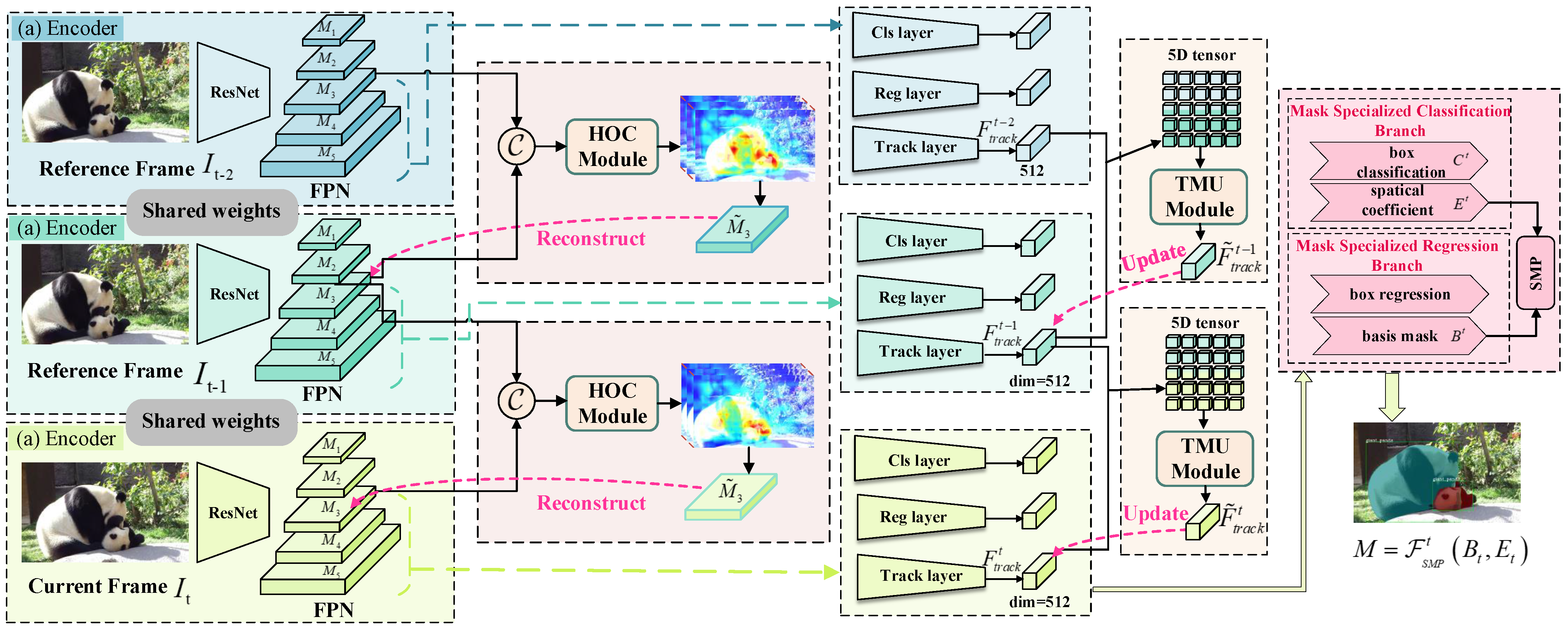
3. Method Overview of HT-VIS
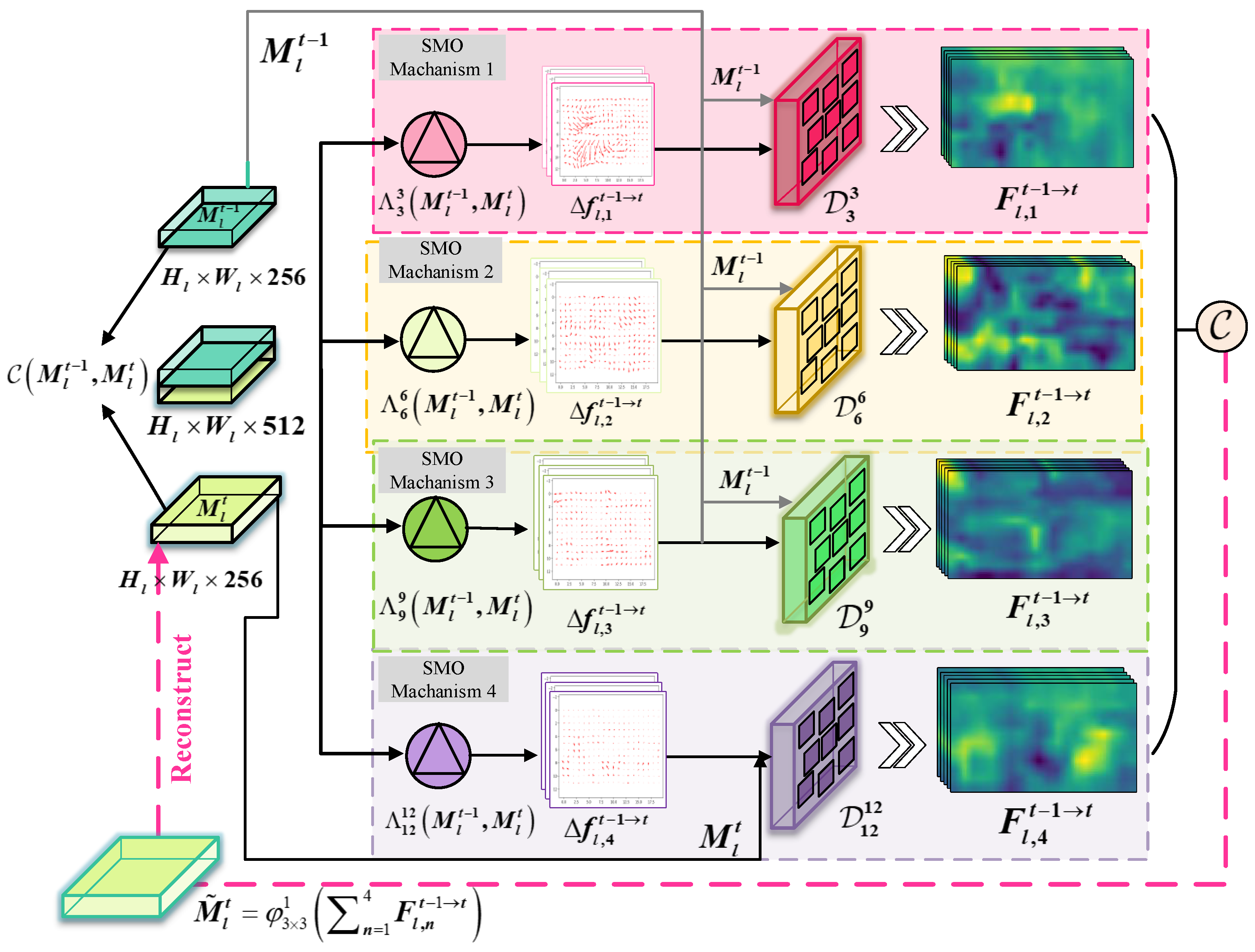
3.1. Hierarchical Offset Compensation Module
3.2. Temporal Memory Update with ConvLSTM
3.3. Objective Function
Tracking Loss
4. Experiments
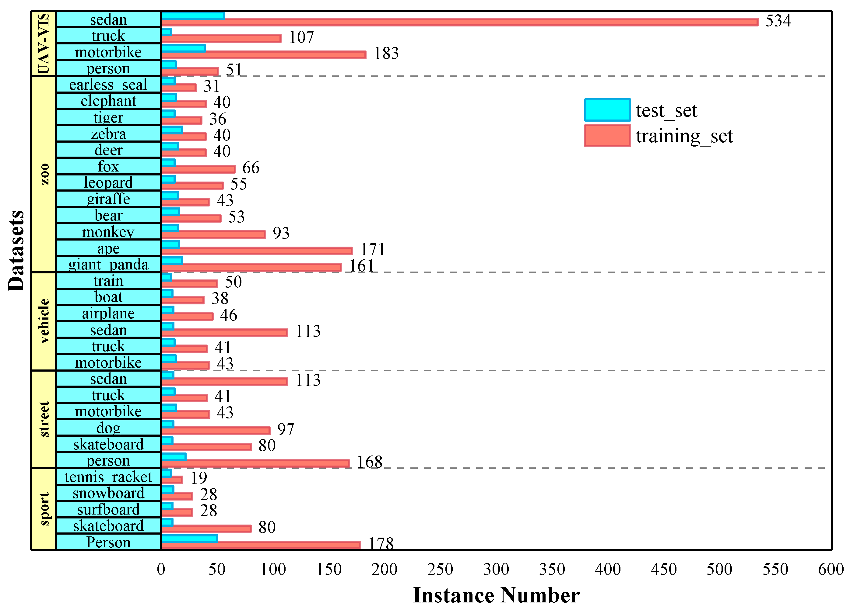
4.1. Dataset
4.2. Implementation Details
4.2.1. Training
4.2.2. Inference
4.3. Evaluation Metrics
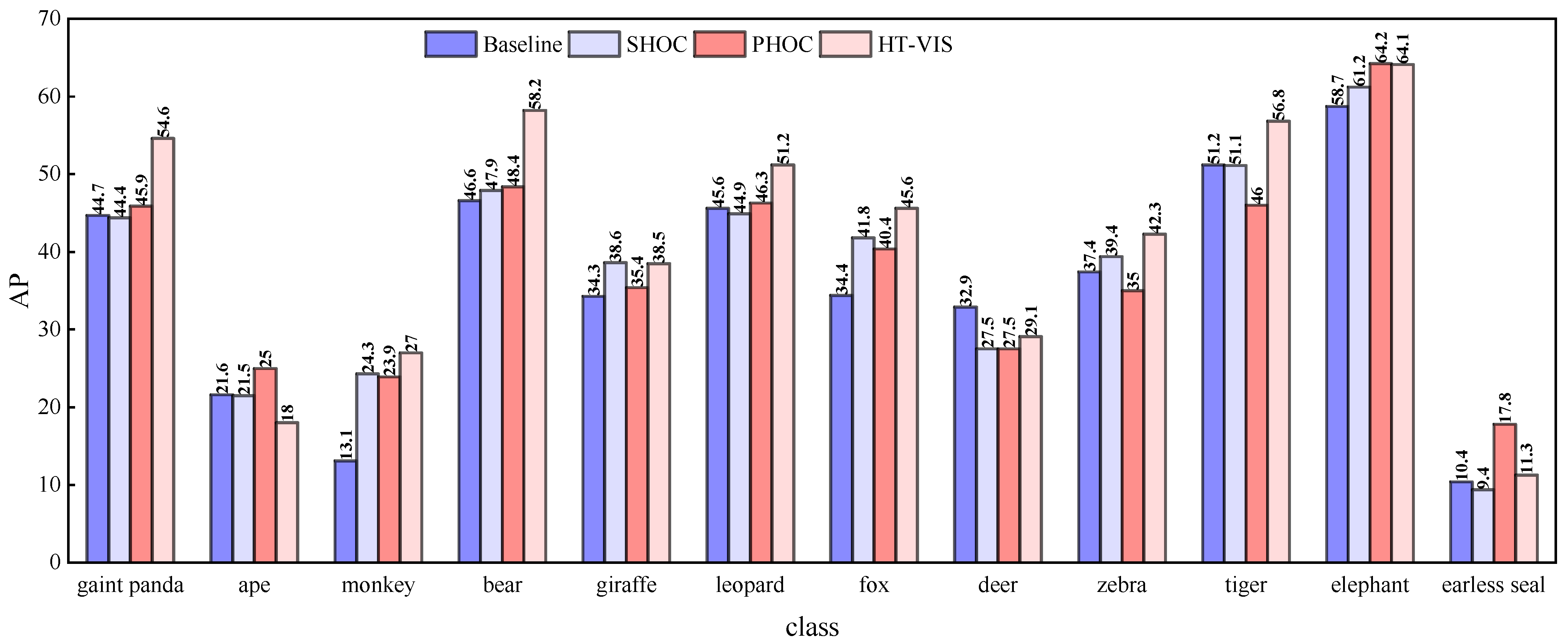
4.4. Performance
4.4.1. Effectiveness of the Hierarchical Offset Compensation
4.4.2. Effect of Temporal Memory
4.4.3. Ablation Study
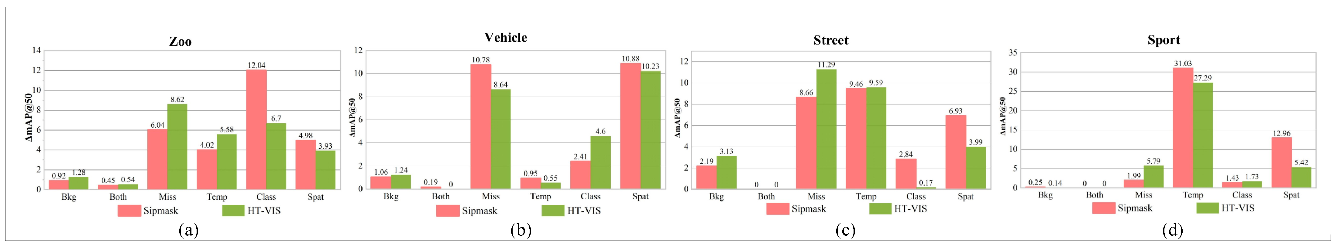
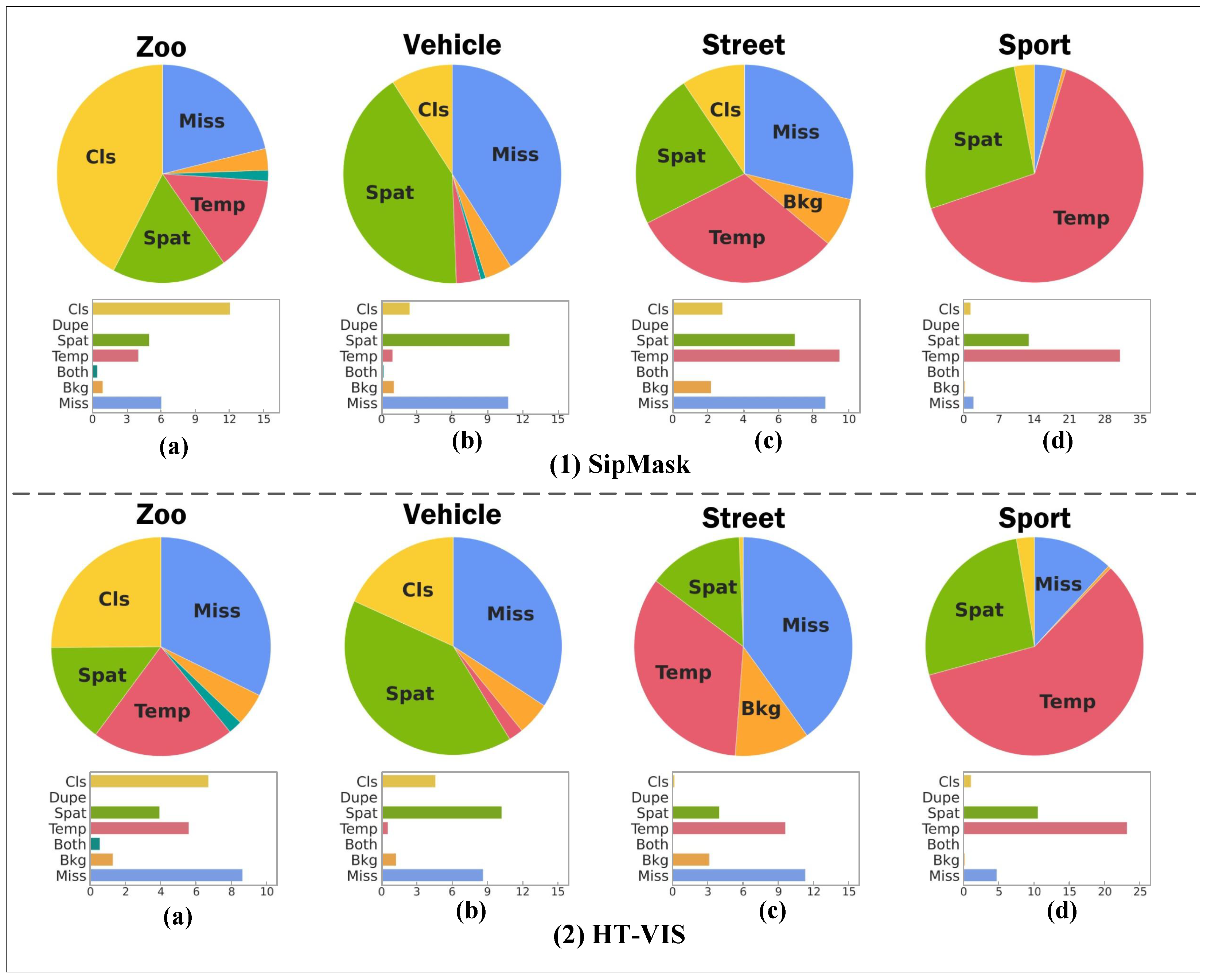
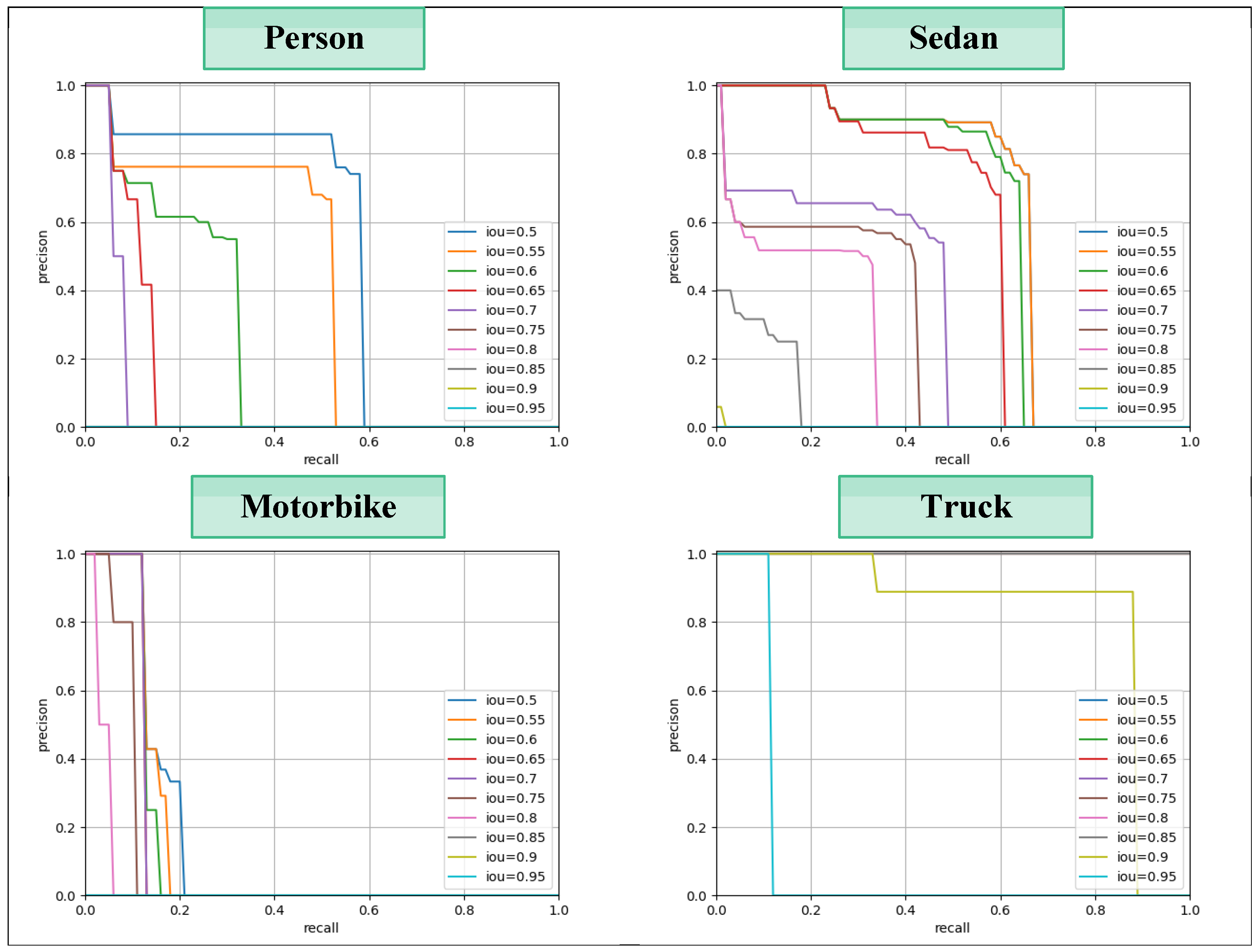
4.5. Error Analysis
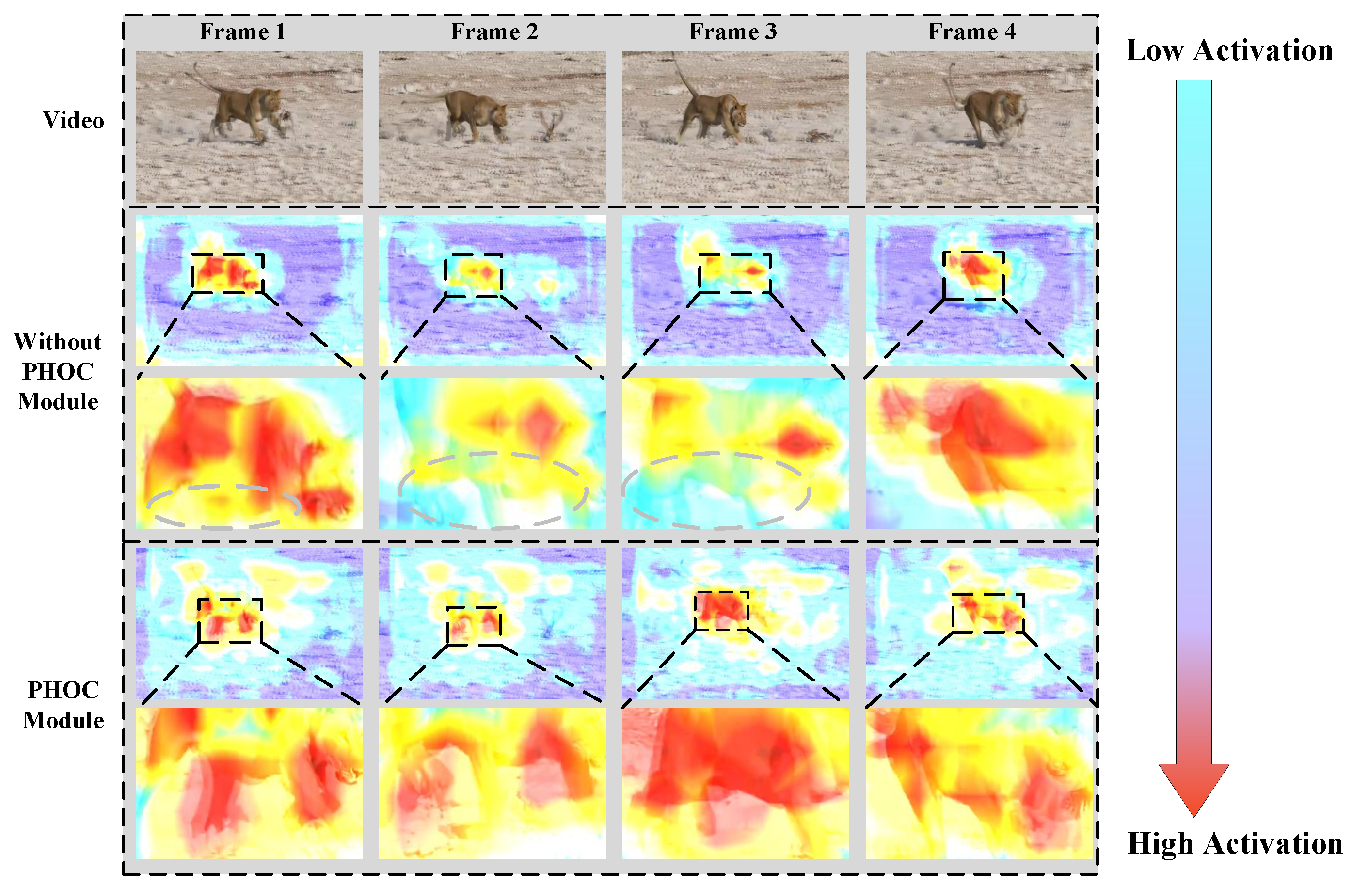
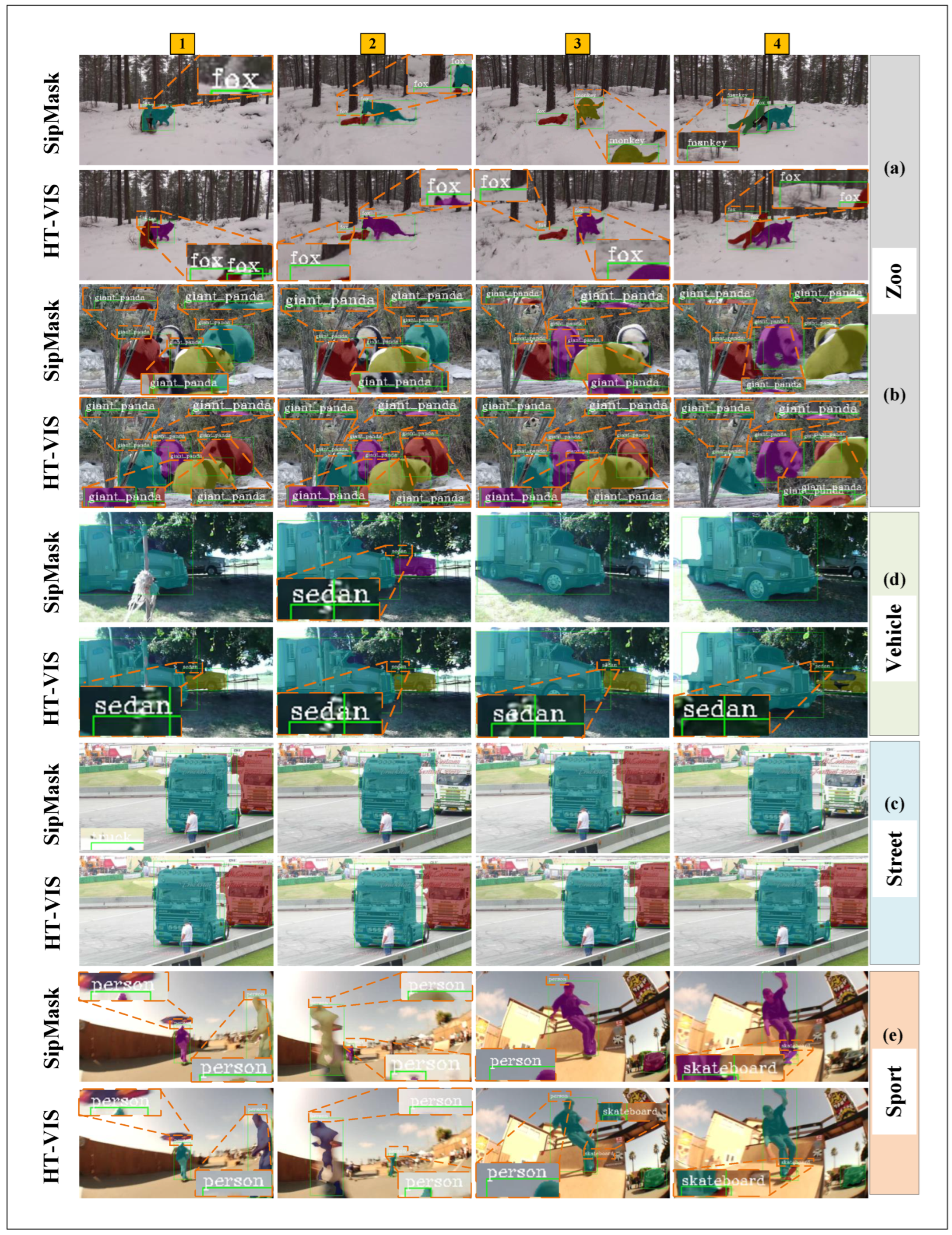
4.5.1. Visualisation
4.5.2. Comparing with Existing Methods
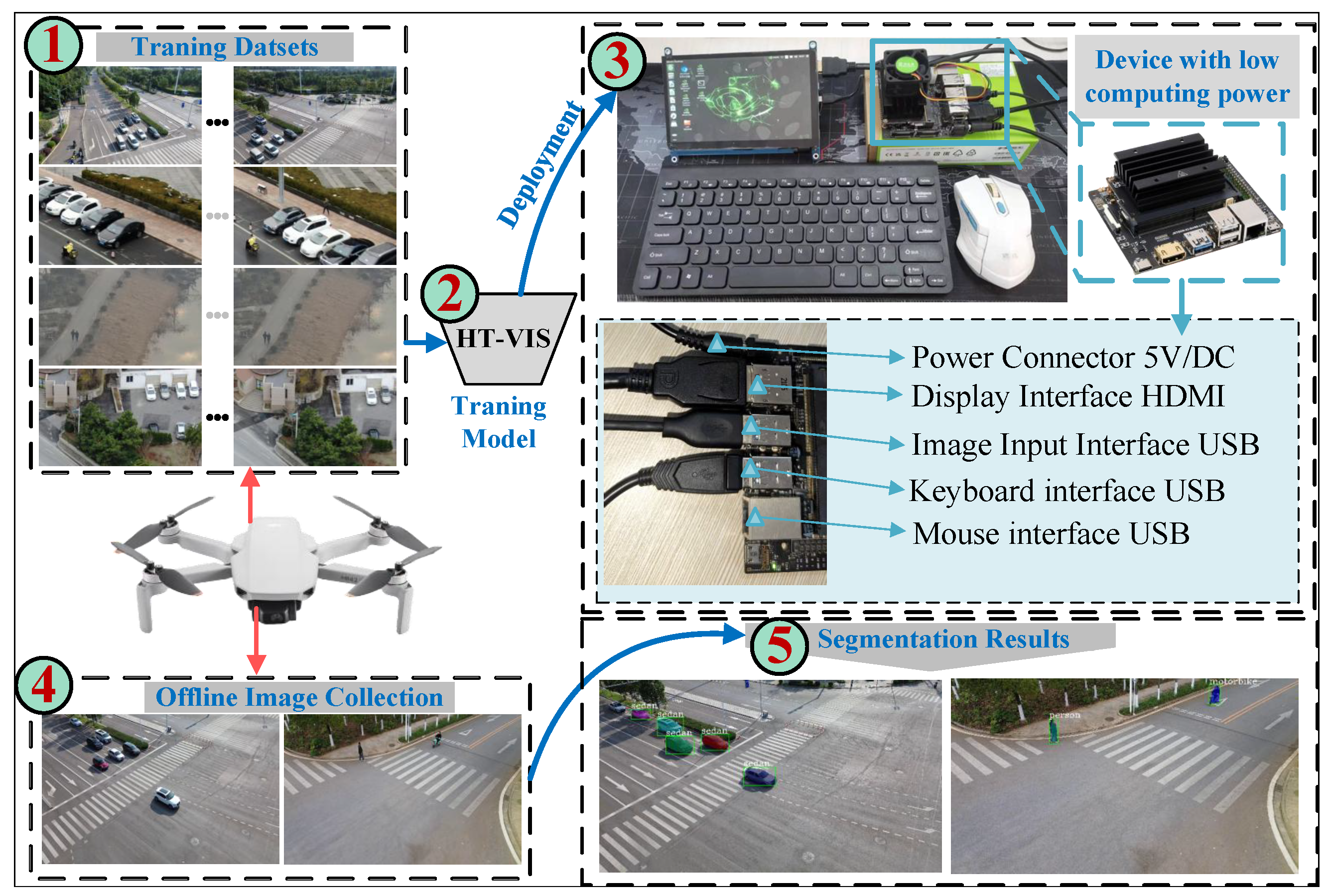
4.6. Edge Device of Deployment
5. Conclusions
6. Discussion
7. Limitations and Future Work
Author Contributions
Funding
Institutional Review Board Statement
Informed Consent Statement
Data Availability Statement
Conflicts of Interest
References
- Lee, M.; Choi, M.; Yang, T.; Kim, J.; Kim, J.; Kwon, O.; Cho, N. A Study on the Advancement of Intelligent Military Drones: Focusing on Reconnaissance Operations. IEEE Access 2024, 12, 55964–55975. [Google Scholar] [CrossRef]
- Sangeetha, R.; Srivastava, Y.; Hemanth, C.; Naicker, H.S.; Kumar, A.P.; Nair, S.V. Unmanned Aerial Surveillance and Tracking System in Forest Areas for Poachers and Wildlife. IEEE Access 2024, 12, 187572–187586. [Google Scholar] [CrossRef]
- Zhu, L.; Zhang, Q.; Chen, K.; Ma, Q.; Chen, S.; Zhang, S.; Yuan, Y. Lightweight Self-Supervised Recognition of Small-Sample Ships Using Micro-Doppler Signatures and UAV-based UWB Radar. IEEE Trans. Instrum. Meas. 2024, 73, 8504210. [Google Scholar] [CrossRef]
- Wan, Z.; Lan, Y.; Xu, Z.; Shang, K.; Zhang, F. DAU-YOLO: A Lightweight and Effective Method for Small Object Detection in UAV Images. Remote Sens. 2025, 17, 1768. [Google Scholar] [CrossRef]
- Nowakowski, M.; Berger, G.S.; Braun, J.; Mendes, J.a.; Bonzatto Junior, L.; Lima, J. Advance Reconnaissance of UGV Path Planning Using Unmanned Aerial Vehicle to Carry Our Mission in Unknown Environment. In Proceedings of the Iberian Robotics Conference, Coimbra, Portugal, 22–24 November 2023; Springer: Berlin/Heidelberg, Germany, 2023; pp. 50–61. [Google Scholar] [CrossRef]
- Li, C.; Li, G.; Song, Y.; He, Q.; Tian, Z.; Xu, H.; Liu, X. Fast forest fire detection and segmentation application for UAV-assisted mobile edge computing system. IEEE Internet Things J. 2023, 11, 26690–26699. [Google Scholar] [CrossRef]
- Caelles, S.; Maninis, K.K.; Pont-Tuset, J.; Leal-Taixé, L.; Cremers, D.; Van Gool, L. One-shot video object segmentation. In Proceedings of the IEEE Conference on Computer Vision and Pattern Recognition, Honolulu, HI, USA, 21–26 July 2017; pp. 221–230. [Google Scholar]
- Pont-Tuset, J.; Perazzi, F.; Caelles, S.; Arbeláez, P.; Sorkine-Hornung, A.; Van Gool, L. The 2017 davis challenge on video object segmentation. arXiv 2017, arXiv:1704.00675. [Google Scholar] [CrossRef]
- Perazzi, F.; Khoreva, A.; Benenson, R.; Schiele, B.; Sorkine-Hornung, A. Learning video object segmentation from static images. In Proceedings of the IEEE Conference on Computer Vision and Pattern Recognition, Honolulu, HI, USA, 21–26 July 2017; pp. 2663–2672. [Google Scholar]
- Wang, H.; Jiang, X.; Ren, H.; Hu, Y.; Bai, S. Swiftnet: Real-time video object segmentation. In Proceedings of the IEEE/CVF Conference on Computer Vision and Pattern Recognition, Nashville, TN, USA, 19–25 June 2021; pp. 1296–1305. [Google Scholar]
- Sun, J.; Mao, Y.; Dai, Y.; Zhong, Y.; Wang, J. Munet: Motion uncertainty-aware semi-supervised video object segmentation. Pattern Recognit. 2023, 138, 109399. [Google Scholar] [CrossRef]
- Wang, Y.; Zhang, W.; Wang, L.; Yang, F.; Lu, H. Temporal consistent portrait video segmentation. Pattern Recognit. 2021, 120, 108143. [Google Scholar] [CrossRef]
- Lan, M.; Zhang, J.; Wang, Z. Coherence-aware context aggregator for fast video object segmentation. Pattern Recognit. 2023, 136, 109214. [Google Scholar] [CrossRef]
- Li, P.; Zhang, Y.; Yuan, L.; Xu, X. Fully transformer-equipped architecture for end-to-end referring video object segmentation. Inf. Process. Manag. 2024, 61, 103566. [Google Scholar] [CrossRef]
- Yang, L.; Fan, Y.; Xu, N. Video Instance Segmentation. In Proceedings of the International Conference on Computer Vision, Seoul, Republic of Korea, 27 October–2 November 2019. [Google Scholar]
- Cao, J.; Anwer, R.M.; Cholakkal, H.; Khan, F.S.; Pang, Y.; Shao, L. Sipmask: Spatial information preservation for fast image and video instance segmentation. In Proceedings of the Computer Vision–ECCV 2020: 16th European Conference, Glasgow, UK, 23–28 August 2020; Part XIV 16. Springer: Berlin/Heidelberg, Germany, 2020; pp. 1–18. [Google Scholar]
- Liu, D.; Cui, Y.; Tan, W.; Chen, Y. Sg-net: Spatial granularity network for one-stage video instance segmentation. In Proceedings of the IEEE/CVF Conference on Computer Vision and Pattern Recognition, Nashville, TN, USA, 19–25 June 2021; pp. 9816–9825. [Google Scholar]
- Fu, Y.; Yang, L.; Liu, D.; Huang, T.S.; Shi, H. CompFeat: Comprehensive Feature Aggregation for Video Instance Segmentation. In Proceedings of the National Conference on Artificial Intelligence, Islamabad, Pakistan, 5–7 April 2021. [Google Scholar] [CrossRef]
- Li, M.; Li, S.; Li, L.; Zhang, L. Spatial Feature Calibration and Temporal Fusion for Effective One-stage Video Instance Segmentation. In Proceedings of the IEEE/CVF Conference on Computer Vision and Pattern Recognition (CVPR), Nashville, TN, USA, 19–25 June 2021. [Google Scholar]
- Bertasius, G.; Torresani, L. Classifying, Segmenting, and Tracking Object Instances in Video with Mask Propagation. In Proceedings of the IEEE/CVF Conference on Computer Vision and Pattern Recognition (CVPR), Seattle, WA, USA, 14–19 June 2019. [Google Scholar]
- Liu, H.; Soto, R.; Xiao, F.; Yong, J.L. YolactEdge: Real-time Instance Segmentation on the Edge. In Proceedings of the International Conference on Robotics and Automation, Xian, China, 30 May–5 June 2021. [Google Scholar] [CrossRef]
- Yang, S.; Fang, Y.; Wang, X.; Li, Y.; Fang, C.; Shan, Y.; Feng, B.; Liu, W. Crossover learning for fast online video instance segmentation. In Proceedings of the IEEE/CVF International Conference on Computer Vision, Montreal, BC, Canada, 11–17 October 2021; pp. 8043–8052. [Google Scholar]
- Athar, A.; Mahadevan, S.; Ošep, A.; Leal-Taixé, L.; Leibe, B. STEm-Seg: Spatio-temporal Embeddings for Instance Segmentation in Videos. In Proceedings of the Computer Vision–ECCV 2020: 16th European Conference, Glasgow, UK, 23–28 August 2020. [Google Scholar] [CrossRef]
- Li, X.; Wang, J.; Li, X.; Lu, Y. Video instance segmentation by instance flow assembly. IEEE Trans. Multimed. 2022, 25, 7469–7479. [Google Scholar] [CrossRef]
- Wu, J.; Liu, Q.; Jiang, Y.; Bai, S.; Yuille, A.; Bai, X. In defense of online models for video instance segmentation. In Proceedings of the European Conference on Computer Vision, Tel Aviv, Israel, 23–27 October 2022; pp. 588–605. [Google Scholar]
- Li, J.; Yu, B.; Rao, Y.; Zhou, J.; Lu, J. Tcovis: Temporally consistent online video instance segmentation. In Proceedings of the IEEE/CVF International Conference on Computer Vision, Paris, France, 2–3 October 2023; pp. 1097–1107. [Google Scholar]
- Wang, Y.; Xu, Z.; Wang, X.; Shen, C.; Cheng, B.; Shen, H.; Xia, H. End-to-end video instance segmentation with transformers. In Proceedings of the IEEE/CVF Conference on Computer Vision and Pattern Recognition, Nashville, TN, USA, 19–25 June 2021; pp. 8741–8750. [Google Scholar]
- Wu, J.; Jiang, Y.; Bai, S.; Zhang, W.; Bai, X. Seqformer: Sequential transformer for video instance segmentation. In Proceedings of the European Conference on Computer Vision, Tel Aviv, Israel, 23–27 October 2022; pp. 553–569. [Google Scholar]
- Cheng, B.; Choudhuri, A.; Misra, I.; Kirillov, A.; Girdhar, R.; Schwing, A.G. Mask2former for video instance segmentation. arXiv 2021, arXiv:2112.10764. [Google Scholar]
- Ying, K.; Zhong, Q.; Mao, W.; Wang, Z.; Chen, H.; Wu, L.Y.; Liu, Y.; Fan, C.; Zhuge, Y.; Shen, C. Ctvis: Consistent training for online video instance segmentation. In Proceedings of the IEEE/CVF International Conference on Computer Vision, Paris, France, 2–3 October 2023; pp. 899–908. [Google Scholar]
- He, K.; Gkioxari, G.; Dollár, P.; Girshick, R. Mask R-CNN. IEEE Trans. Pattern Anal. Mach. Intell. 2017. [Google Scholar]
- Tian, Z.; Shen, C.; Chen, H. Conditional convolutions for instance segmentation. In Proceedings of the Computer Vision–ECCV 2020: 16th European Conference, Glasgow, UK, 23–28 August 2020; Part I 16. Springer: Berlin/Heidelberg, Germany, 2020; pp. 282–298. [Google Scholar]
- Heo, M.; Hwang, S.; Oh, S.W.; Lee, J.Y.; Kim, S.J. Vita: Video instance segmentation via object token association. Adv. Neural Inf. Process. Syst. 2022, 35, 23109–23120. [Google Scholar]
- Huang, D.A.; Yu, Z.; Anandkumar, A. Minvis: A minimal video instance segmentation framework without video-based training. Adv. Neural Inf. Process. Syst. 2022, 35, 31265–31277. [Google Scholar]
- Dai, J.; Qi, H.; Xiong, Y.; Li, Y.; Zhang, G.; Hu, H.; Wei, Y. Deformable Convolutional Networks. In Proceedings of the IEEE International Conference on Computer Vision (ICCV), Venice, Italy, 22–29 October 2017. [Google Scholar]
- Tian, Y.; Zhang, Y.; Fu, Y.; Xu, C. TDAN: Temporally-deformable alignment network for video super-resolution. In Proceedings of the IEEE/CVF Conference on Computer Vision and Pattern Recognition, Seattle, WA, USA, 14–19 June 2020; pp. 3360–3369. [Google Scholar]
- Wang, X.; Chan, K.; Yu, K.; Dong, C.; Loy, C.C. EDVR: Video Restoration with Enhanced Deformable Convolutional Networks. In Proceedings of the 2019 IEEE/CVF Conference on Computer Vision and Pattern Recognition Workshops (CVPRW), Long Beach, CA, USA, 16–20 June 2019. [Google Scholar]
- Bertasius, G.; Torresani, L.; Shi, J. Object detection in video with spatiotemporal sampling networks. In Proceedings of the European Conference on Computer Vision (ECCV), Munich, Germany, 8–14 September 2018; pp. 331–346. [Google Scholar]
- Bertasius, G.; Feichtenhofer, C.; Tran, D.; Shi, J.; Torresani, L. Learning temporal pose estimation from sparsely-labeled videos. Adv. Neural Inf. Process. Syst. 2019, 32, 3027–3038. [Google Scholar]
- Jia, W.; Yang, L.; Jia, Z.; Zhao, W.; Zhou, Y.; Song, Q. TIVE: A toolbox for identifying video instance segmentation errors. Neurocomputing 2023, 545, 126321. [Google Scholar] [CrossRef]
- Kim, H.; Kang, J.; Heo, M.; Hwang, S.; Oh, S.W.; Kim, S.J. VISAGE: Video Instance Segmentation with Appearance-Guided Enhancement. In Proceedings of the European Conference on Computer Vision, Milan, Italy, 29 September–4 October 2024; Springer: Berlin/Heidelberg, Germany, 2024; pp. 93–109. [Google Scholar]


| Notations | Defination |
|---|---|
| l | The layer of FPN |
| n | The number of spatial motion offset (SMO) mechanisms |
| r | dilation factor |
| Sampling center point with offset of 0 | |
| Predefined offset sample location in the regular convolution | |
| The weights of the deformable convolution kernel | |
| The learnable offset from time step to t | |
| Input feature map for HOC module | |
| The output feature map of the deformable convolution on the sample location from the time step to t | |
| A sample point set of a grid | |
| The offset feature of the SMO mechanism from time step to t | |
| The deformable convolution operation with represented by Equation (1) | |
| Standard convolution filter with padding p and dilation rate r in the SMO mechanism | |
| A standard convolution with a stride of s |
| Scene | Model | AP | AP@50 | AP@75 | AR@1 | AR@10 | AR@s | AR@m | AR@l |
|---|---|---|---|---|---|---|---|---|---|
| Zoo | Baseline | 35.9 | 58.3 | 42.1 | 35.6 | 44.5 | 12.0 | 51.4 | 52.7 |
| SHOC | 37.7 (+1.8) | 58.6 (+0.3) | 45.4 (+3.3) | 36.5 (+0.9) | 45.1 (+0.6) | 13.9 (+1.9) | 53.5 (+2.1) | 50.2 | |
| PHOC | 37.9 (+2.0) | 59.1 (+0.8) | 44.9 (+2.8) | 37.0 (+1.4) | 45.2 (+0.7) | 12.5 (+0.5) | 52.1 (+0.7) | 53.0 (+0.3) | |
| Vehicle | Baseline | 38.9 | 66.5 | 37.6 | 41.4 | 45.9 | 38.9 | 31.9 | 54.8 |
| SHOC | 40.6 (+1.7) | 65.0 | 39.6 (+2.0) | 42.9 (+1.5) | 46.3 (+0.4) | 29.4 | 39.2 (+8.7) | 56.6 (+1.8) | |
| PHOC | 41.0 (+2.1) | 65.5 | 44.7 (+7.1) | 44.4 (+3.0) | 47.3 (+1.4) | 36.1 | 40.6 (+8.7) | 57.0 (+2.2) | |
| Street | Baseline | 33.5 | 59.0 | 35.9 | 35.4 | 40.2 | 12.6 | 22.1 | 57.0 |
| SHOC | 36.7 (+3.2) | 63.1 (+4.1) | 37.4 (+1.5) | 39.5 (+4.1) | 44.1 (+3.9) | 15.6 (3.0) | 32.8 (+10.7) | 63.9 (+6.9) | |
| PHOC | 36.3 (+2.8) | 65.6 (+6.6) | 35.7 | 39.9 (+4.5) | 45.4 (+5.2) | 19.1 (+6.5) | 30.8 (+8.7) | 60.3 (+3.3) | |
| Sport | Baseline | 15.0 | 34.3 | 12.7 | 16.5 | 17.9 | 16.1 | 29.5 | 32.5 |
| SHOC | 18.2 (+3.2) | 46.1 (+11.8) | 11.0 | 18.3 (+1.8) | 19.6 (+1.7) | 17.9 (+1.8) | 44.8 (+25.3) | 21.7 | |
| PHOC | 17.8 (+2.8) | 47.2 (+12.9) | 11.6 | 17.7 (+1.2) | 19.0 (+1.1) | 18.0 (+1.9) | 30.2 (+0.7) | 24.2 |
| Scene | Model | AP | AP@50 | AP@75 | AR@1 | AR@10 | AR@s | AR@m | AR@l |
|---|---|---|---|---|---|---|---|---|---|
| Zoo | PHOC | 37.9 | 59.1 | 44.9 | 37.0 | 45.2 | 12.5 | 52.1 | 53.0 |
| +TMU | 41.4 (+3.5) | 61.9 (+2.8) | 46.5 (+1.6) | 39.1 (+2.1) | 48.3 (+3.1) | 15.6 (+3.1) | 54.6 (+2.5) | 54.9 (+1.9) | |
| Vehicle | PHOC | 41.0 | 65.5 | 44.7 | 44.4 | 47.3 | 36.1 | 40.6 | 57.0 |
| +TMU | 41.1 (+0.1) | 65.9 (+0.4) | 42.5 | 44.7 (+0.3) | 47.4 (+0.1) | 37.8 (+1.7) | 30.3 | 57.9 (+0.9) | |
| Street | SHOC | 36.7 | 63.1 | 37.4 | 39.5 | 44.1 | 15.6 | 32.8 | 63.9 |
| +TMU | 38.5 (+0.6) | 65.3 | 40.3 (+2.8) | 40.3 (+2.8) | 45.7 (+0.7) | 16.4 | 36.4 (+1.9) | 61.7 (+4.4) | |
| Sport | SHOC | 18.2 | 46.1 | 11.0 | 18.3 | 19.6 | 17.9 | 44.8 | 21.7 |
| +TMU | 16.3 | 47.6 | 10.1 | 15.1 | 17.6 | 18.0 | 37.0 | 20.8 |
| Module | mAP | mAP@50 | mAP@75 | AR@1 | AR@10 | ||
|---|---|---|---|---|---|---|---|
| SHOC | PHOC | TMU | |||||
| ✘ | ✘ | ✘ | 35.3 | 58.4 | 33.9 | 26.9 | 39.1 |
| ✔ | ✘ | ✘ | 36.7 | 57.5 | 35.5 | 28.0 | 39.9 |
| ✘ | ✔ | ✘ | 35.9 | 58.2 | 34.5 | 27.2 | 40.0 |
| ✔ | ✘ | ✔ | 37.1 | 59.0 | 37.8 | 28.4 | 41.9 |
| ✘ | ✔ | ✔ | 37.4 | 58.9 | 39.9 | 29.6 | 42.2 |
| Model | Layer | AP | AP@50 | AP@75 | AR@1 | AR@10 | AR@s | AR@m | AR@l |
|---|---|---|---|---|---|---|---|---|---|
| baseline | ✘ | 35.9 | 58.3 | 42.1 | 35.6 | 44.5 | 12.0 | 51.4 | 52.7 |
| SHOC | 1 | 38.6 | 58.8 | 42.1 | 37.2 | 46.1 | 15.8 | 54.9 | 50.1 |
| 2 | 39.7 | 60.2 | 44.1 | 37.0 | 45.7 | 16.4 | 51.8 | 52.2 | |
| 3 | 37.7 | 58.6 | 45.4 | 36.5 | 45.1 | 13.9 | 53.5 | 50.2 | |
| 4 | 39.8 | 59.6 | 44.6 | 36.9 | 46.5 | 15.9 | 50.9 | 53.7 | |
| 5 | 40.2 | 59.5 | 56.3 | 37.4 | 47.0 | 16.4 | 52.4 | 54.8 | |
| PHOC | 1 | 37.1 | 57.1 | 41.4 | 35.0 | 42.8 | 13.7 | 49.8 | 47.1 |
| 2 | 39.6 | 62.3 | 43.0 | 37.4 | 45.8 | 15.8 | 52.2 | 49.3 | |
| 3 | 37.9 | 59.1 | 44.9 | 37.0 | 45.2 | 12.5 | 52.1 | 53.0 | |
| 4 | 39.6 | 60.1 | 44.9 | 38.1 | 47.1 | 19.6 | 51.9 | 53.1 | |
| 5 | 39.5 | 58.5 | 45.7 | 37.1 | 46.9 | 19.1 | 51.9 | 53.6 |
| Layer | AP | AP@50 | AP@75 | AR@1 | AR@10 | AR@s | AR@m | AR@l | AP | AP@50 | AP@75 | AR@1 | AR@10 | AR@s | AR@m | AR@l |
|---|---|---|---|---|---|---|---|---|---|---|---|---|---|---|---|---|
| SHOC+TMU | PHOC+TMU | |||||||||||||||
| 1 | 39.7 | 59.8 | 43.0 | 38.3 | 46.6 | 13.9 | 50.6 | 54.6 | 38.9 | 60.6 | 41.6 | 38.2 | 46.0 | 13.6 | 48.2 | 53.6 |
| 2 | 40.7 | 63.0 | 45.3 | 39.1 | 47.3 | 18.0 | 49.9 | 55.1 | 39.8 | 59.6 | 45.2 | 38.4 | 47.3 | 16.5 | 50.9 | 54.2 |
| 3 | 40.8 | 60.6 | 47.0 | 38.6 | 47.1 | 16.9 | 51.2 | 53.2 | 41.4 | 61.9 | 46.5 | 39.1 | 48.3 | 15.6 | 54.6 | 54.9 |
| 4 | 40.5 | 61.1 | 47.1 | 38.6 | 47.0 | 15.8 | 53.9 | 52.2 | 40.7 | 60.5 | 45.9 | 37.9 | 46.5 | 14.7 | 51.0 | 53.3 |
| 5 | 41.2 | 61.0 | 46.9 | 37.8 | 47.5 | 19.2 | 53.2 | 54.4 | 39.7 | 59.9 | 44.5 | 38.2 | 46.1 | 19.0 | 50.9 | 52.8 |
| Layer | AP | AP@50 | AR@1 | AR@10 | AP | AP@50 | AR@1 | AR@10 | AP | AP@50 | AR@1 | AR@10 | AP | AP@50 | AR@1 | AR@10 |
|---|---|---|---|---|---|---|---|---|---|---|---|---|---|---|---|---|
| SHOC+TMU | PHOC+TMU | |||||||||||||||
| w/o Tracking | with Tracking | w/o Tracking | with Tracking | |||||||||||||
| 1 | 26.4 | 42.8 | 25.5 | 32.8 | 39.7 | 59.8 | 38.3 | 46.6 | 25.8 | 44.7 | 25.6 | 30.6 | 38.9 | 60.6 | 38.2 | 46.0 |
| 2 | 30.6 | 50.8 | 30.8 | 37.2 | 40.7 | 63.0 | 39.1 | 47.3 | 29.1 | 47.7 | 30.4 | 36.1 | 39.8 | 59.6 | 38.4 | 47.3 |
| 3 | 28.7 | 50.5 | 26.7 | 34.9 | 40.8 | 60.6 | 38.6 | 47.1 | 28.5 | 47.1 | 27.8 | 35.4 | 41.4 | 61.9 | 39.1 | 48.3 |
| 4 | 29.0 | 46.8 | 28.1 | 36.1 | 40.5 | 61.1 | 38.6 | 47.0 | 26.4 | 46.6 | 27.5 | 34.1 | 40.7 | 60.5 | 37.9 | 46.5 |
| 5 | 28.1 | 44.9 | 27.1 | 33.3 | 41.2 | 61.0 | 37.8 | 47.5 | 29.5 | 47.5 | 29.2 | 36.6 | 39.7 | 59.9 | 38.2 | 46.1 |
| Error Type | Error Definition | |
|---|---|---|
| False Positive (FP) | background error (Bkg) | and for all foreground categories with ground truth |
| classification error (Cls) | and with incorrect category | |
| both classifications and location error (Both) | and with incorrect category | |
| duplication error (Dup) | and with correct category but another higher sequence IoU has matched corresponding GT | |
| spatial segmentation error (Spat) | and with correct category | |
| temporal association error (Temp) | and with correct category | |
| False Negative (FN) | missed ground truth error (Miss) | All GT are not detected from foreground and not covered by any error. |
| Scene | Model | AP | AP@50 | AP@75 | AR@1 | AR@10 | AR@s | AR@m | AR@l |
|---|---|---|---|---|---|---|---|---|---|
| Zoo | SipMask | 35.9 | 58.3 | 42.1 | 35.6 | 44.5 | 12.0 | 51.4 | 52.7 |
| STMask | 36.9 | 52.5 | 41.5 | 34.2 | 41.5 | 13.5 | 45.9 | 43.0 | |
| YolactEdge | 31.5 | 58.9 | 41.5 | - | - | - | - | - | |
| CrossVIS | 37.5 | 56.5 | 43.3 | 36.6 | 47.3 | 15.0 | 52.4 | 53.2 | |
| HT-VIS | 41.4 | 61.9 | 46.5 | 39.1 | 48.3 | 15.6 | 54.6 | 54.9 | |
| Vehicle | SipMask | 38.9 | 66.5 | 37.6 | 41.4 | 45.9 | 38.9 | 31.9 | 54.8 |
| STMask | 27.8 | 44.4 | 27.6 | 31.2 | 33.0 | 18.3 | 13.6 | 44.5 | |
| YolactEdge | 32.4 | 59.5 | 34.0 | - | - | - | - | - | |
| CrossVIS | 39.1 | 61.7 | 38.9 | 40.8 | 45.1 | 38.3 | 37.2 | 53.1 | |
| HT-VIS | 41.1 | 65.9 | 42.5 | 44.7 | 47.4 | 37.8 | 30.3 | 57.9 | |
| Street | SipMask | 33.5 | 59.0 | 35.9 | 35.4 | 40.2 | 12.3 | 22.1 | 57.0 |
| STMask | 35.7 | 62.7 | 34.5 | 38.7 | 42.6 | 13.1 | 32.5 | 47.2 | |
| YolactEdge | 31.2 | 57.1 | 35.4 | - | - | - | - | - | |
| CrossVIS | 38.6 | 62.1 | 41.2 | 38.7 | 45.5 | 30.7 | 32.1 | 57.0 | |
| HT-VIS | 38.2 | 65.3 | 40.3 | 41.4 | 45.7 | 16.4 | 36.4 | 61.7 | |
| Sport | SipMask | 15.0 | 34.3 | 12.7 | 16.5 | 17.9 | 16.1 | 29.5 | 32.5 |
| STMask | 10.9 | 33.7 | 8.1 | 12.3 | 14.2 | 13.9 | 29.5 | 11.7 | |
| YolactEdge | 16.9 | 40.2 | 11.2 | - | - | - | - | - | |
| CrossVIS | 14.4 | 35.7 | 11.6 | 17.5 | 19.4 | 18.2 | 30.2 | 31.7 | |
| HT-VIS | 18.2 | 46.1 | 11.0 | 18.3 | 19.6 | 17.9 | 44.8 | 21.7 |
| Model | Year | mAP@50 | mAP | FPS | Para.(M) | |
|---|---|---|---|---|---|---|
| CNN-based Methods | SipMask [16] | 2020 | 58.4 | 35.3 | 24 | 33 |
| CrossVIS [22] | 2021 | 57.9 | 36.2 | 28 | 37 | |
| HT-VIS(SHOC) | - | 59.0 | 37.1 | 12 | 36 | |
| HT-VIS(PHOC) | - | 58.9 | 37.4 | 14 | 35 | |
| transformer-based Methods | SeqFormer [28] | 2022 | 60.4 | 39.4 | 220 | |
| MinVIS [34] | 2022 | 65.8 | 44.2 | - | - | |
| CTVIS [30] | 2023 | 62.3 | 45.2 | - | - | |
| VISAGE [41] | 2024 | 64.6 | 46.7 | - | - | |
| Parameter | Specification |
|---|---|
| Size | |
| CPU | 4-Core ARM A57@1.43GHz |
| APU | Tegra X1 |
| GPU | 128-core Maxwell |
| Memory | 32GB Micro SD Card |
| Display Interface | HDMI and DisplayPort |
| Graphics Memory | 4GB 64-bit LPDDR4 |
| Data Transmission Interfaces | 4 × USB3.0, USB 2.0, Micro-B |
| ComputPerformance | 473 GFlops |
Disclaimer/Publisher’s Note: The statements, opinions and data contained in all publications are solely those of the individual author(s) and contributor(s) and not of MDPI and/or the editor(s). MDPI and/or the editor(s) disclaim responsibility for any injury to people or property resulting from any ideas, methods, instructions or products referred to in the content. |
© 2025 by the authors. Licensee MDPI, Basel, Switzerland. This article is an open access article distributed under the terms and conditions of the Creative Commons Attribution (CC BY) license (https://creativecommons.org/licenses/by/4.0/).
Share and Cite
Huang, Y.; Zhang, Y.; He, Z.; Deng, Y. Video Instance Segmentation Through Hierarchical Offset Compensation and Temporal Memory Update for UAV Aerial Images. Sensors 2025, 25, 4274. https://doi.org/10.3390/s25144274
Huang Y, Zhang Y, He Z, Deng Y. Video Instance Segmentation Through Hierarchical Offset Compensation and Temporal Memory Update for UAV Aerial Images. Sensors. 2025; 25(14):4274. https://doi.org/10.3390/s25144274
Chicago/Turabian StyleHuang, Ying, Yinhui Zhang, Zifen He, and Yunnan Deng. 2025. "Video Instance Segmentation Through Hierarchical Offset Compensation and Temporal Memory Update for UAV Aerial Images" Sensors 25, no. 14: 4274. https://doi.org/10.3390/s25144274
APA StyleHuang, Y., Zhang, Y., He, Z., & Deng, Y. (2025). Video Instance Segmentation Through Hierarchical Offset Compensation and Temporal Memory Update for UAV Aerial Images. Sensors, 25(14), 4274. https://doi.org/10.3390/s25144274