3.1. The Overall Structure of SFEF-Net
As mentioned in
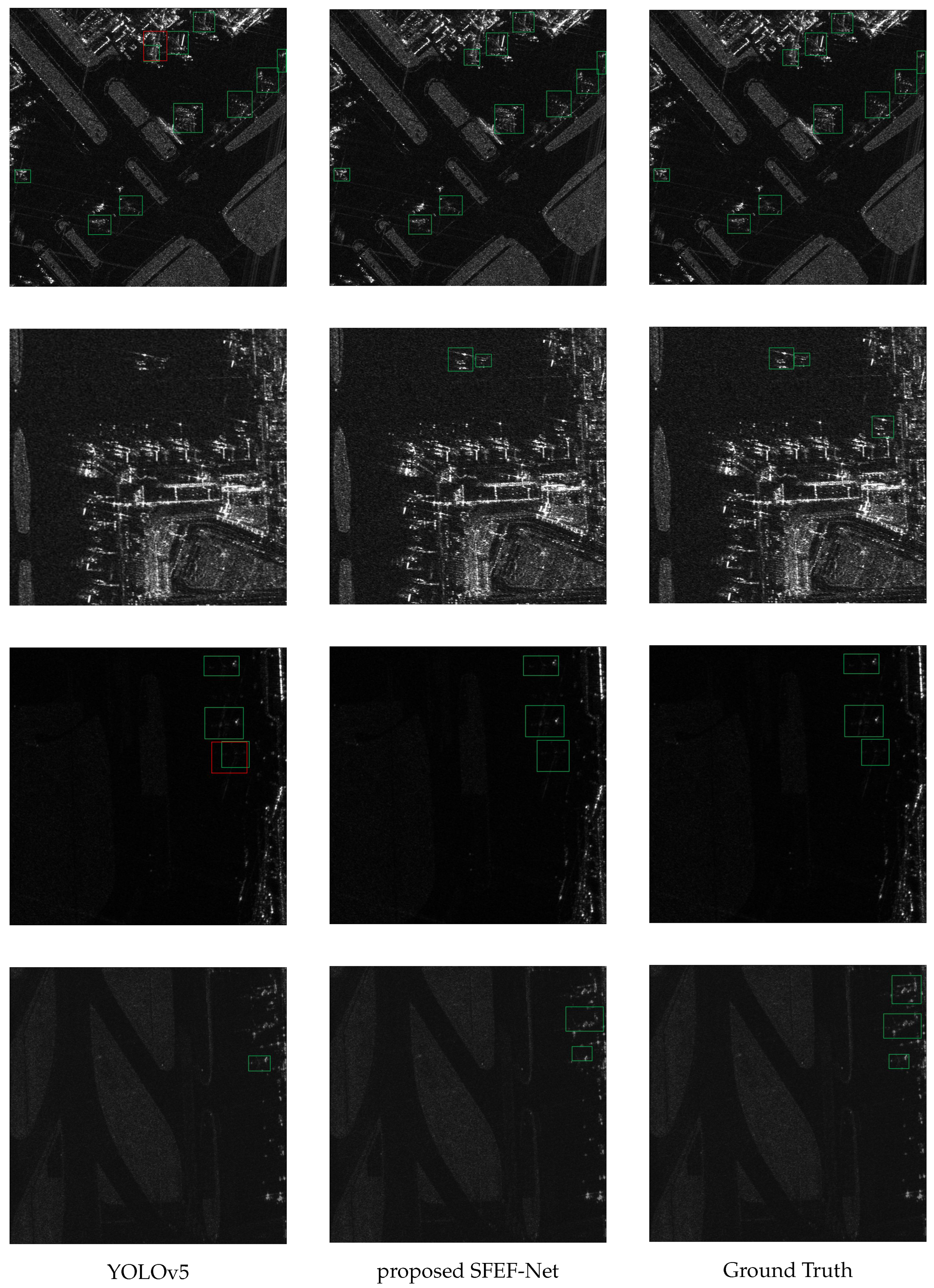
Section 2.1, single-stage methods have shown good performance in terms of speed and accuracy. As one of the most outstanding algorithms in single-stage methods, YOLOv5 has been applied in many practical scenarios, and its generalization has been widely validated. Based on this, we have chosen YOLOv5 as our baseline.
Figure 2 illustrates the overall structure of SFEF-Net, which consists of three components: backbone, neck, and head.
Backbone. The backbone processes the input images and generates multi-scale feature maps. Following the design principles of YOLOv5, we incorporated cross-stage partial connection [
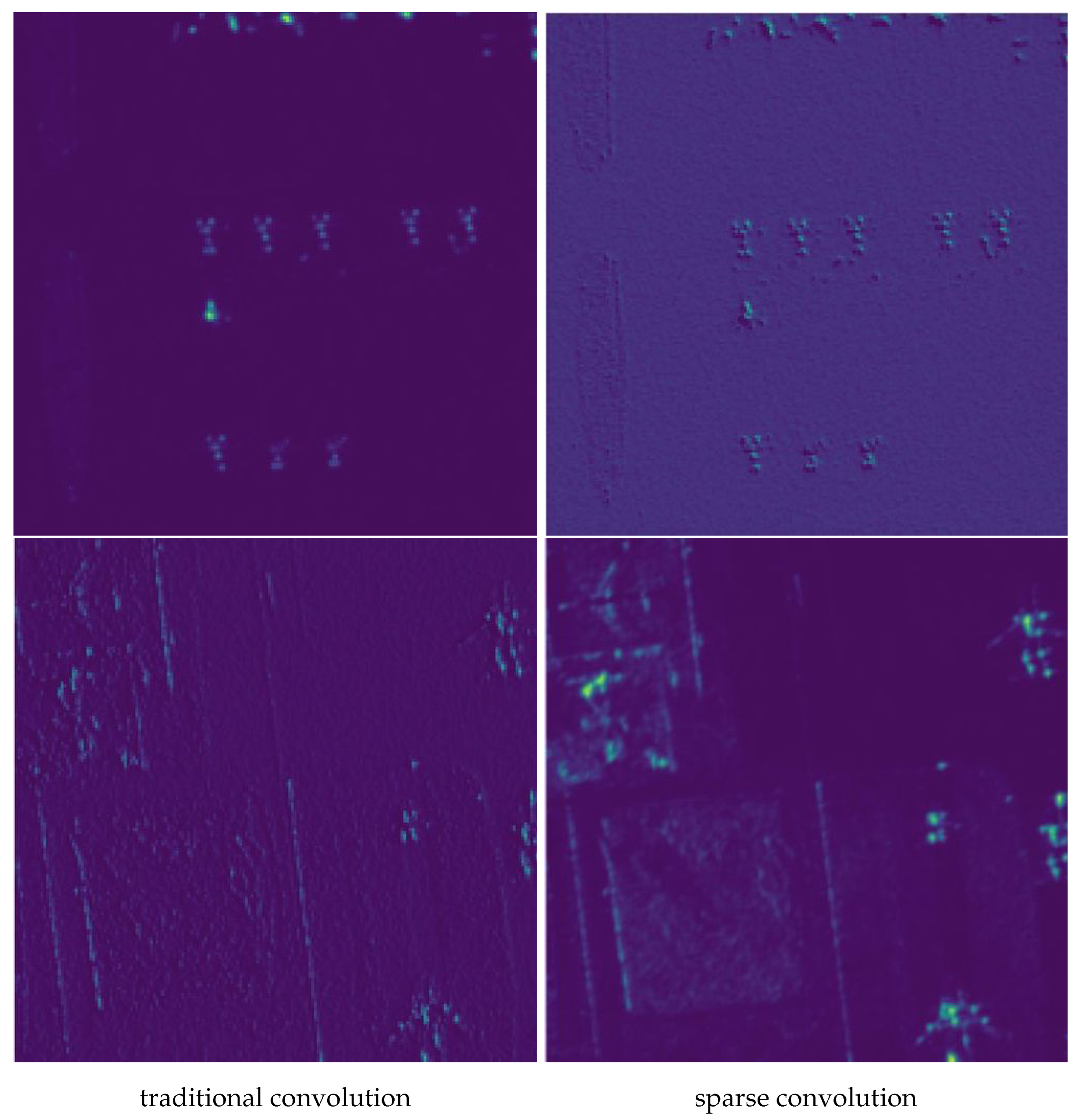
63] into the backbone because it has lightweight parameters but powerful feature extraction capabilities. In addition, we replaced some traditional convolutions in the backbone with the proposed sparse convolutions for extracting discrete features of aircraft.
Neck. The neck aggregates the feature maps extracted by the backbone, enhancing the model’s ability to detect objects across multiple scales. YOLOv5 uses PANet as its neck, which has inherent limitations in cross-layer information exchange. To address this drawback, we designed a novel global information fusion and distribution module that allows information to be exchanged between all feature maps, which improves the model’s detection accuracy in challenging background conditions.
Head and Loss. The head predicts the positions and categories of potential objects. To a certain degree, the value of the loss function reflects the quality of the prediction results, and the gradient of the loss function indicates the direction of parameter updates. For predicting positions, we utilize the CIoU loss, as described in [
64]. In addition, to enhance category prediction, we developed a noise-robust loss function that mitigates the harmful effects of annotation noise.
3.2. Backbone: CSPDarkNet Integrated with Sparse Convolution
CSP connection. As mentioned above, we use the CSPDarkNet integrated with sparse convolution as the backbone. As shown in
Figure 3, the CSP connection forwards the input feature maps through two branches. The key feature of the right branch is the residual block, which was proposed in [
11] to alleviate the issue of degradation in very deep neural networks. The left branch utilizes sparse convolution, whose detailed structure will be elaborated upon subsequently. CSP connection has powerful feature extraction capabilities while maintaining lightweight parameters. This is because traditional CNN architectures, such as DarkNet, adopt a single-branch design. This design leads to a large amount of redundant gradients during the forward propagation process, resulting in limited learning capacity. Instead, CSP employs two branches (left and right) that have different gradient flows. Particularly, the left branch does not have complex residual blocks, significantly lowering the amount of parameters and computational complexity. Moreover, the CSP connection has sufficient versatility, which allows it to be conveniently integrated into almost all existing CNN.
Sparse Convolution. The computation of 2D convolution involves two main steps: (1) selecting a subset of values from the input feature map
x within a small, rectangular region
R; (2) calculating a weighted aggregation of these selected points, where the weights are learnable parameters of the convolutional kernel. For example, for a 3 × 3 convolutional kernel, the sampling region
would be as follows:
where each element in R represents the vertical and horizontal offsets of the sampling points relative to the center of the convolutional kernel, respectively. Hence, for each point
on the output feature map
y, we have:
where
denotes a spatial coordinate that iterates over all positions in the output feature map
y.
represents the activation value at coordinate
in the output feature map
y. The set
R refers to the collection of sampling offsets relative to the kernel’s center; for the standard 3 × 3 traditional convolution shown,
as defined in Equation (
1). Each
within
R is a specific sampling offset.
is the learnable kernel weight associated with the offset
. Finally,
represents the activation value from the corresponding location in the input feature map
x, accessed by adding the offset
to the output coordinate
.
Dilated convolution [
65], also known as atrous convolution, is an extension of traditional convolution. It selects sampling points over a larger range. For example, with a dilation rate of 1 and a kernel size of 3, the sampling range
will be:
Dilated convolution offers a larger receptive field in comparison to traditional convolution, making it more suitable for extracting discrete aircraft features in SAR images. Several studies, such as [
57,
58], have successfully utilized dilated convolution to achieve certain progress. However, dilated convolution still samples at fixed positions, which results in inherent information loss. The fundamental reason for information loss is that different positions on the input feature map are sampled with entirely different probabilities. If a point
, then its sampling probability is 1; otherwise, it is 0. If the crucial discrete features of the airplane happen to be located outside of
, there is a high possibility that the detection results will be incorrect.
To overcome the limitations of fixed sampling in dilated convolution, the sparse convolution we proposed further expands on this concept by introducing channel-specific randomized sampling patterns. The fundamental computation remains a weighted aggregation similar to Equation (
2), but the crucial difference lies in how the sampling offsets are determined.
Let
denote the activation at position
in the
c-th output feature map (where
), and
denote the activation at position
in the
-th input feature map (where
). The sparse convolution operation is defined as:
where
represents the learnable kernel weight and
is the channel-specific set of
K randomly sampled offsets for the
c-th output channel.
The generation and properties of the sampling offset set are crucial:
Initialization and Fixation: The set for each output channel c is generated once during model initialization. Specifically, for each c, sampling offsets are selected uniformly at random without replacement from a predefined neighborhood () centered at the origin. These randomly determined sampling positions remain fixed throughout all subsequent training and inference stages.
Channel Independence: Crucially, the sampling patterns are generated independently for each output channel c. This means is generally different from if .
This per-channel independent random sampling strategy allows different channels to potentially focus on different spatial locations, leading to enhanced coverage. Consider a specific feature point within the sampling neighborhood. The probability of it being selected by a single channel is . The probability of this point not being selected by any of the independent output channels is . As increases, this probability rapidly approaches zero (e.g., for , it is ), ensuring high coverage of the input feature map and mitigating potential information loss. It is important to note that while the randomly generated sampling locations remain fixed after initialization, the associated kernel weights w, initialized using standard methods and subsequently optimized via backpropagation during training just like conventional convolutional layers. Sparse convolution, as implemented here, does not involve learning or dynamically adjusting the sampling locations themselves.
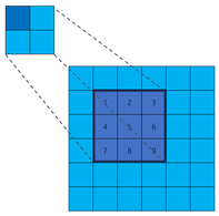
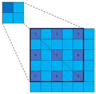
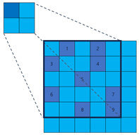
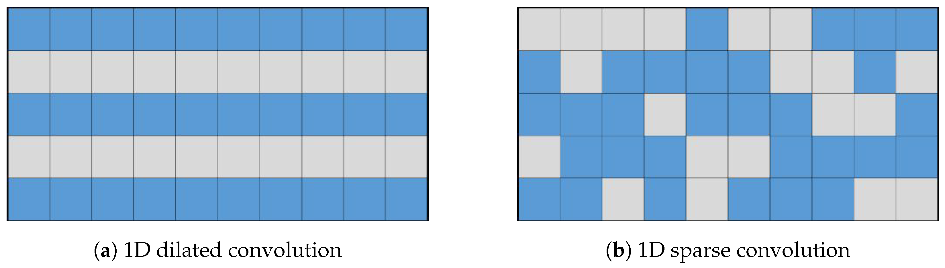
To illustrate the fundamental difference in sampling strategy and its impact on information coverage more clearly, let us consider a simplified one-dimensional analogy, as depicted in
Figure 4. While our actual application involves 2D convolutions, this 1D example effectively highlights the core distinction between fixed versus randomized channel-independent sampling. Let the input feature map be
. The output channel of the dilated convolution
is 10, with a kernel size of 3 and a dilation rate of 1. The parameters of the sparse convolution
are kept consistent with the dilation convolution. The dilation convolution and sparse convolution are depicted in
Figure 4, with each column representing an output channel. The blue cells represent the sampled positions, while the gray cells represent the discarded positions. In the dilation convolution, all channels discard
and
. If important features happen to be present in these positions, it can result in inherent information loss. On the other hand, in sparse convolution, similar information loss does not occur.
Although presented in 1D for simplicity, the same principle applies to 2D sparse convolution: by having each output channel independently sample random 2D offsets within a larger neighborhood, we ensure diverse coverage of the 2D input feature map across the channel dimension.
In addition, it is worth noting that sparse convolution does not increase the number of parameters compared to traditional and dilated convolution. When the kernel size of the convolution is
k, and the input and output channels are
and
, respectively, the number of parameters for all three of them is
. To provide a clearer comparison, we have summarized the main characteristics and illustrations of the three methods in
Table 1.
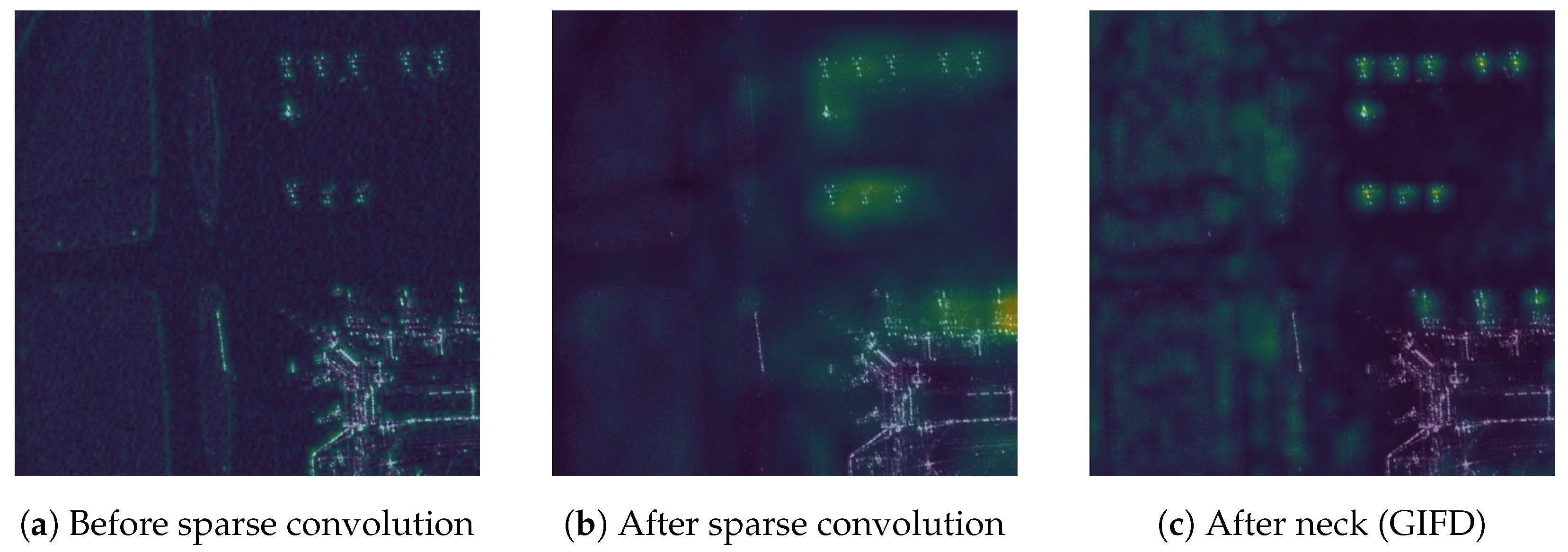
3.3. Global Information Fusion and Distribution (GIFD) Module
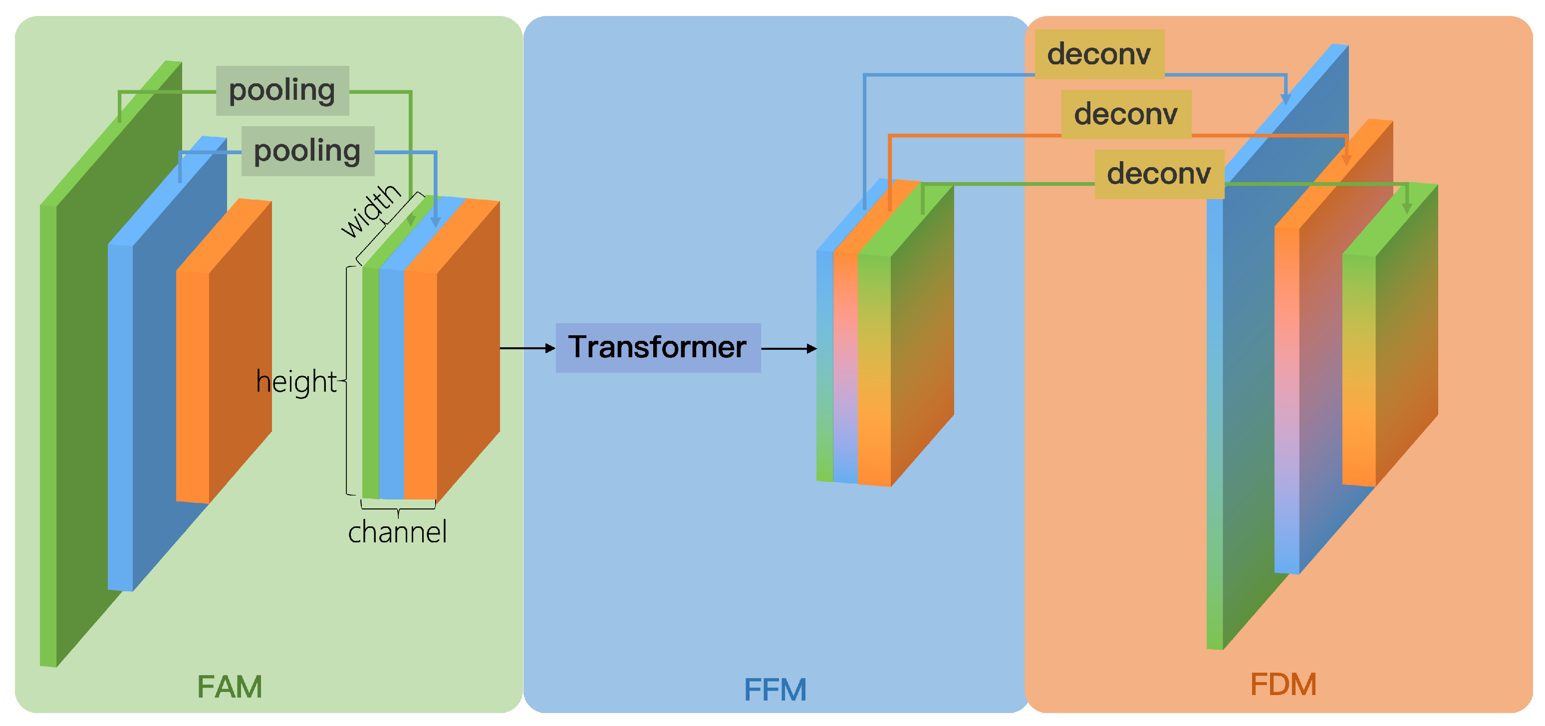
We designed the global information fusion and distribution (GIFD) module to effectively fuse multi-scale feature maps extracted by the backbone (typically P3, P4, and P5, corresponding to stride 8, 16, and 32, respectively), enhancing the model’s multi-scale detection capability while achieving a balance between speed and accuracy. The conceptual illustration of GIFD is shown in
Figure 5. Unlike traditional feature fusion networks like FPN and PANet, which primarily exchange information between adjacent layers and can suffer from information loss across distant scales, GIFD employs a global fusion mechanism via its feature fusion module (FFM). GIFD consists of three key sub-modules: feature alignment module (FAM), feature fusion module (FFM), and feature distribution module (FDM).
Feature Alignment Module (FAM). As depicted conceptually in
Figure 5 (left part), the FAM receives multi-scale feature maps P3, P4, and P5 from the backbone (corresponding to strides 8, 16, and 32, respectively). To prepare these features for efficient global fusion in the subsequent FFM module, FAM aligns them all to a common, reduced spatial resolution, specifically, the
P5 scale (stride 32). This spatial alignment is achieved by applying appropriate downsampling operations to the higher-resolution feature maps P3 and P4 to match the spatial dimensions of P5, for example, using average pooling or max pooling. The specific choice of downsampling method is not considered a critical design element here, as the primary goal is simply to reduce the spatial resolution efficiently to achieve scale alignment before concatenation. Following these alignment steps, the processed P3, P4, and P5 feature maps, now all sharing the same P5 spatial resolution, are concatenated along the channel dimension. This produces the unified feature map
, which compactly represents information from all input scales at the minimal resolution, thus reducing the computational load for the FFM while maintaining low latency.
Feature Fusion Module (FFM). Inspired by ViT [
39], the FFM takes the concatenated and aligned feature map
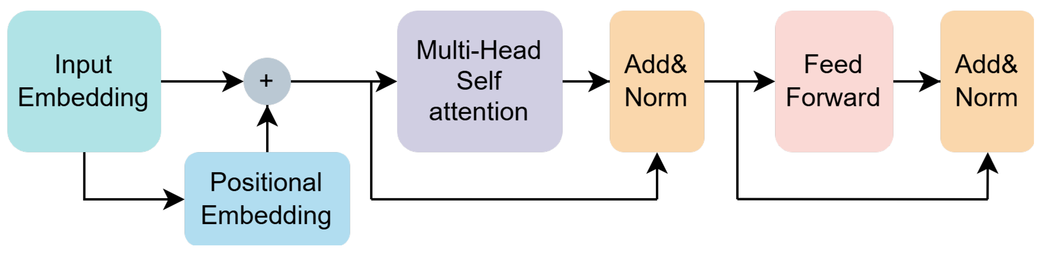
(at P5 scale) as input. It employs Transformer encoders, whose key component is multi-head self-attention (MHSA), to perform global information fusion across all spatial locations and aggregated channel information. The detailed architecture of the Transformer encoder used is shown in
Figure 6. By leveraging the Transformer’s ability to model long-range dependencies, FFM effectively breaks the information flow barriers inherent in traditional convolutional neck structures. The output of the FFM is the fused feature map
, which maintains the same P5 spatial resolution and channel dimension as
.
The architecture of the Transformer encoder is shown in
Figure 6. Generally, the Transformer encoder takes a sequence of 1D vectors as input and outputs vectors of the same length. To handle 2D images, we reshape the feature map
into
, where
H,
W, and
C represent the height, width, and channels of
, respectively, and
represents the number of feature points. In addition, we employ a learnable linear layer as positional embedding to capture the positional information in the sequence, allowing the model to better learn the relationships between elements at different positions in the input sequence. Therefore, the input vector sequence, after positional encoding, goes through the MHSA layer, normalization layer, and feed-forward layer, resulting in the fused feature map
.
Feature Distribution Module (FDM). The fused feature map
obtained from FFM, while contextually rich, exists only at the single, reduced P5 scale. To generate the multi-scale feature representations required by standard object detection heads, the FDM module distributes this fused information back to multiple spatial resolutions, specifically targeting the original P3, P4, and P5 scales. As illustrated conceptually in
Figure 5 (right side), FDM effectively performs the inverse process of FAM. First, the channels of
are split into three segments, corresponding to the target P3, P4, and P5 output paths. The segment destined for the P5 output path passes through a 3 × 3 convolutional layer, with stride 1 and padding 1. This operation maintains the P5 spatial resolution while potentially refining the features, producing the final
feature map. The segment allocated for the P4 output path is first upsampled by a factor of 2 to restore the P4 spatial resolution (corresponding to stride 16). This upsampling can be achieved using standard methods, for example, a transposed convolution layer ultimately producing the
feature map. Likewise, the segment corresponding to the P3 output path undergoes a similar process but with an upsampling factor of 4 to restore the P3 spatial resolution (stride 8), potentially also involving methods like transposed convolution, which yields the final
feature map. The resulting set of feature maps
, possessing spatial resolutions corresponding to strides 8, 16, and 32, respectively, and appropriate channel dimensions, directly meet the requirements for the subsequent multi-scale detection heads. This completes the process of the global information fusion and distribution (GIFD) module.
3.4. Noise-Robust Loss
To mitigate the negative impact of incorrect annotations in the dataset on the prediction results, we have designed a noise-robust loss. The NR Loss assigns dynamic weights to erroneous annotations, which are often outliers during the training process, allowing the model to focus more effectively on the correct annotations.
Our NR Loss is an improvement upon the classical cross-entropy loss function. The formula for binary cross-entropy (BCE) is as follows:
where
y and
represent ground truth and prediction probability, respectively. Cross-entropy measures the difference between the predicted probabilities of the model and the ground truth. By minimizing the cross-entropy loss, the model can better fit the training data and improve its classification performance. However, one main drawback of cross entropy is that it is too sensitive to outliers [
66]. For example, when the ground truth is 0 and the model’s predicted result varies from 0 to 1, the value of the cross-entropy loss function will change. On the one hand, when the predicted probability is close to 0, the loss grows slowly. On the other hand, when the predicted probability approaches 1, the loss escalates rapidly. Formally, NR Loss adds a dynamic adjustment factor to the cross-entropy loss. We define NR Loss as follows:
where
is a hyperparameter that represents the degree of penalty for outliers. In NR Loss, we use
to measure the likelihood of a sample being an outlier. When
is close to 1, it indicates a significant discrepancy between the model’s prediction and the ground truth, suggesting that it is likely an outlier and will be assigned a lower weight. On the other hand, when the model’s prediction is similar to the ground truth, it suggests that the sample is less likely to be an outlier and will receive a relatively larger weight. We can also adjust the degree of penalty for outliers by changing
. When
increases, the penalty becomes stronger, and vice versa.


