
High-Performance Four-Channel Tactile Sensor for Measuring the Magnitude and Orientation of Forces

Abstract
1. Introduction
2. Four-Channel Tactile Sensor
2.1. The Structural Design and Fabrication of Tactile Sensors
2.2. The Principle and Testing of Individual Channels
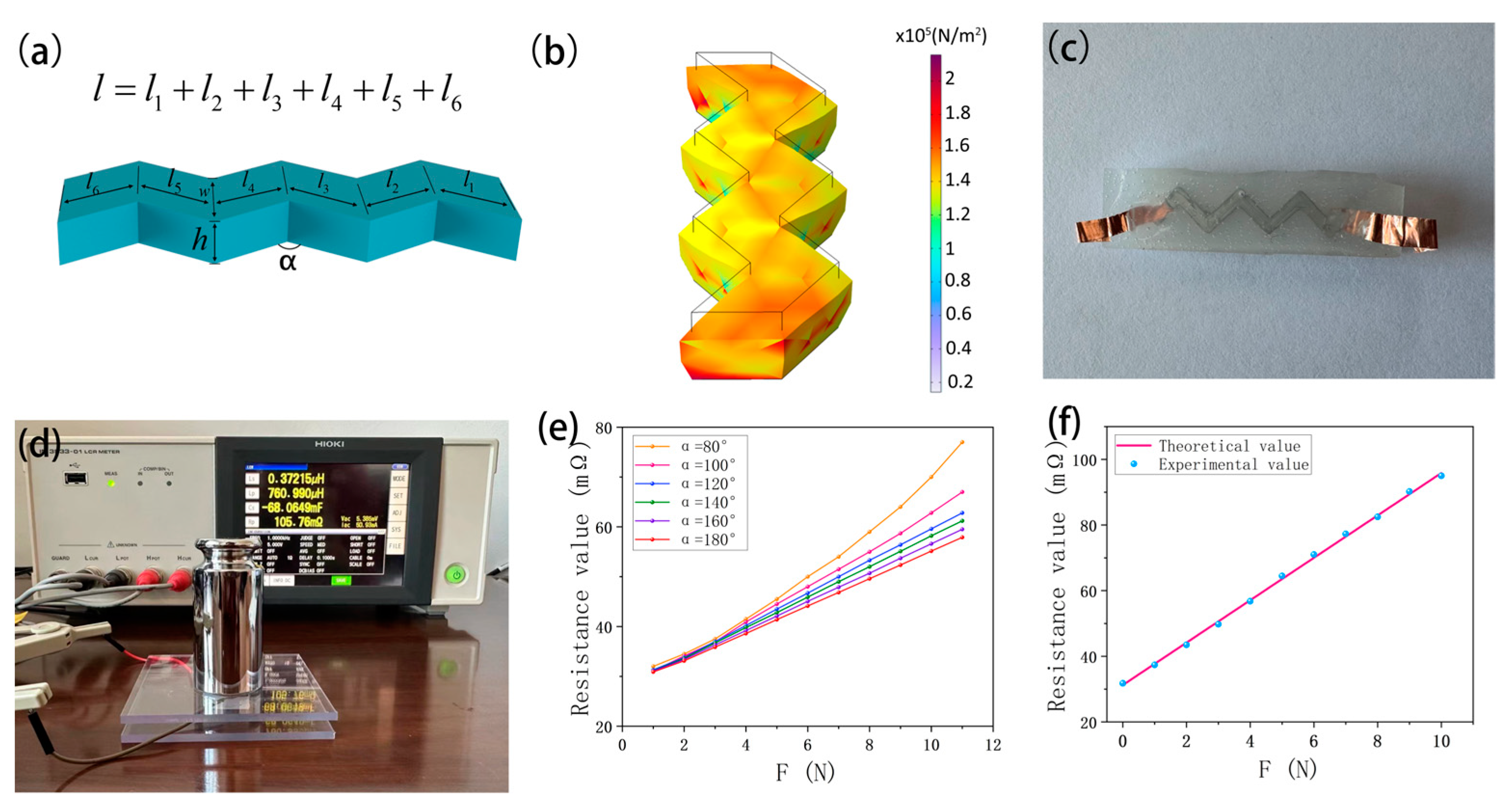
2.2.1. The Operating Principle of an Individual Channel
2.2.2. Single-Channel Testing and Results
- (1)
- The impact of channel curvature α on linearity
- (2)
- Linearity test
- (3)
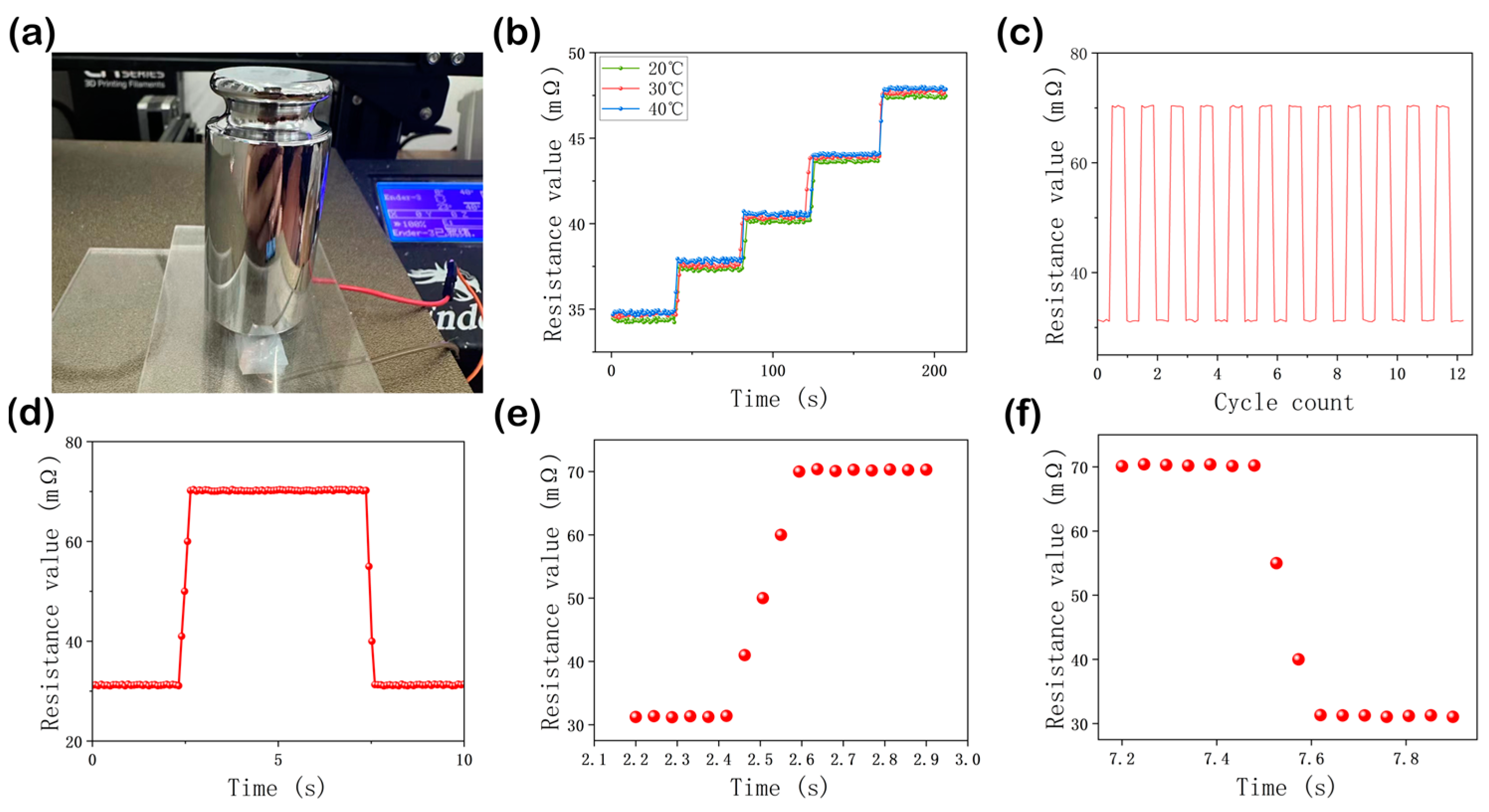
- Performance test
2.3. The Working Principle and Testing of the Four-Channel Tactile Sensor
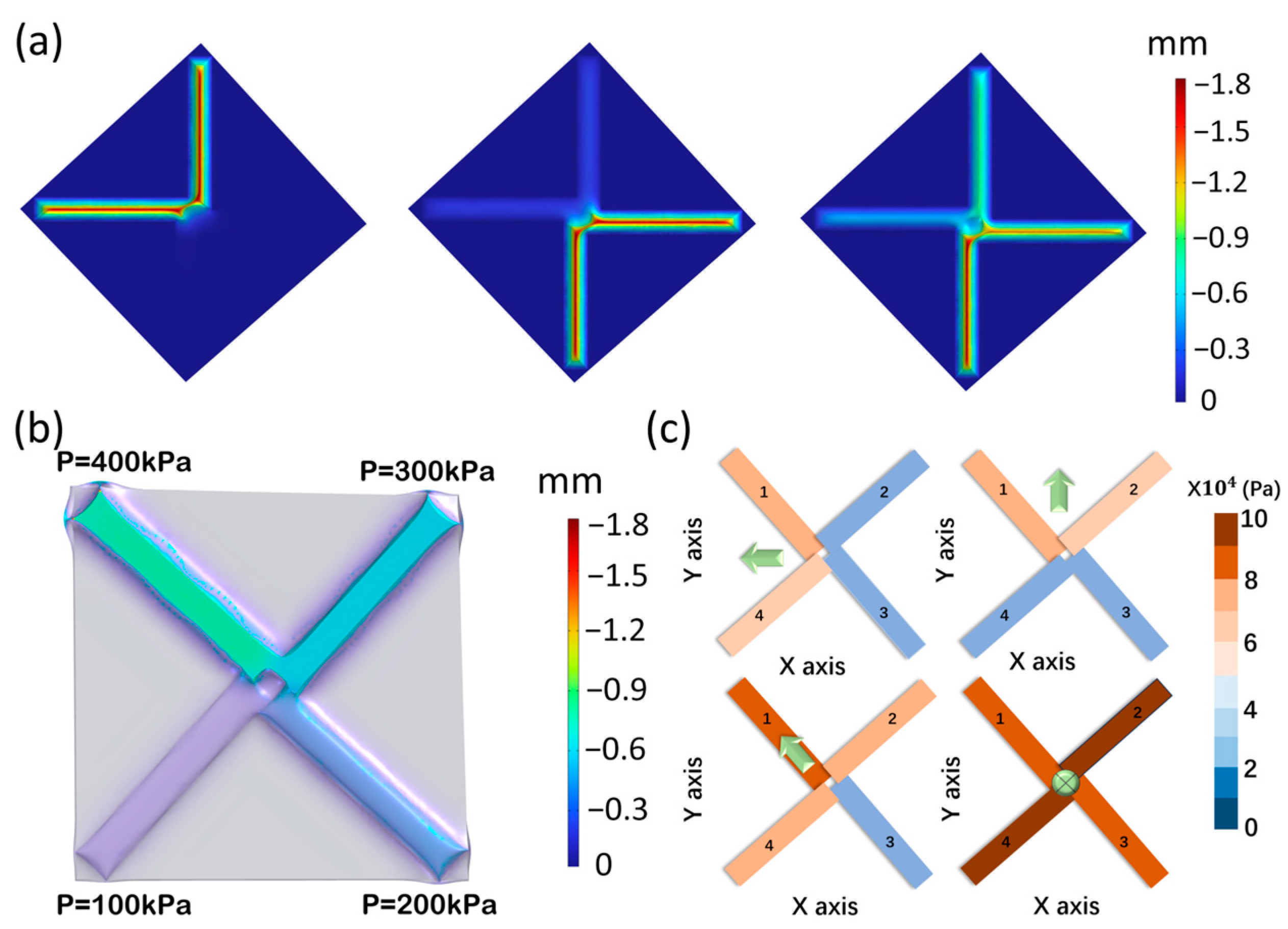
2.3.1. The Force Calculation Model of the Sensor
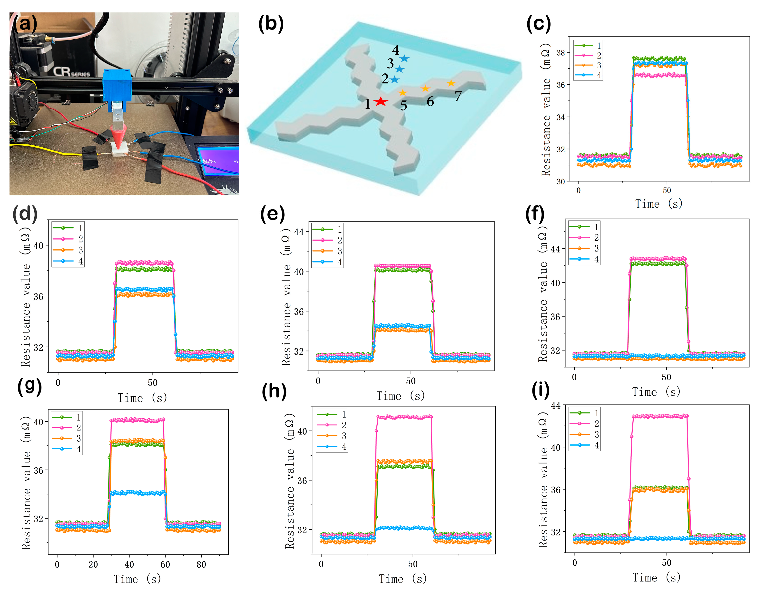
2.3.2. Testing of the Four-Channel Tactile Sensor
- (1)
- Simulat
- (2)
- Experiment and Results
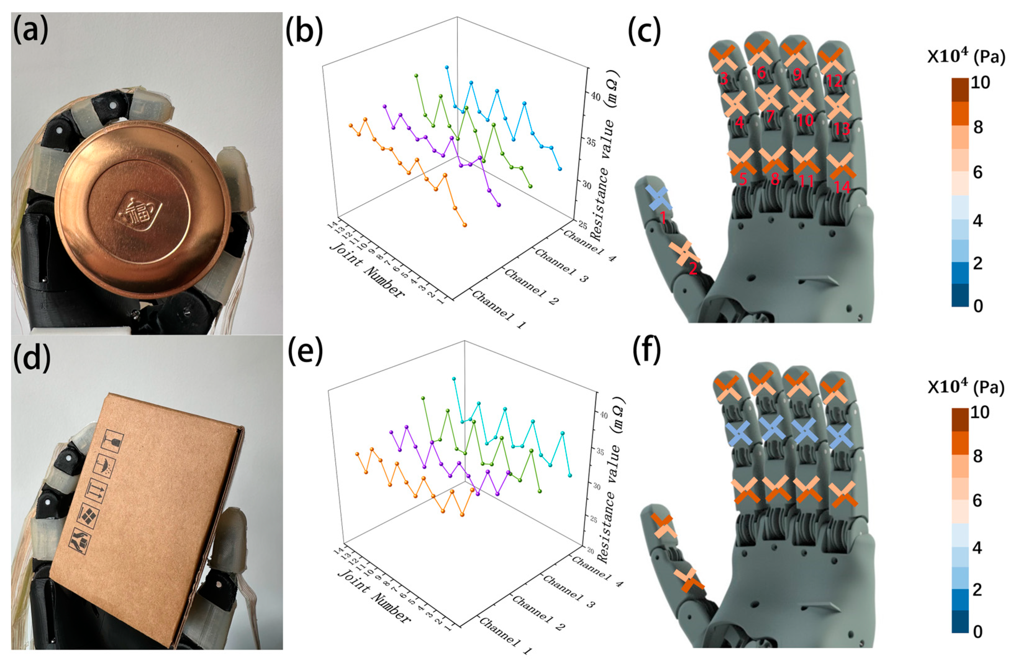
3. Underactuated Robotic Hand for Wearable Applications
- (1)
- Robotic hand grasping cylindrical object:
- (2)
- Robotic hand grasping rectangular object:
4. Discussion
5. Conclusions
Author Contributions
Funding
Institutional Review Board Statement
Informed Consent Statement
Data Availability Statement
Acknowledgments
Conflicts of Interest
References
- Xue, L.; Wang, W.; Guo, Y.; Liu, G.; Wan, P. Flexible Polyaniline/Carbon Nanotube Nanocomposite Film-Based Electronic Gas Sensors. Sens. Actuators B Chem. 2017, 244, 47–53. [Google Scholar] [CrossRef]
- Wang, X.; Liu, Z.; Zhang, T. Flexible Sensing Electronics for Wearable/Attachable Health Monitoring. Small 2017, 13, 1602790. [Google Scholar] [CrossRef] [PubMed]
- Choi, Y.; Brown, E.C.; Haile, S.M.; Jung, W. Electrochemically Modified, Robust Solid Oxide Fuel Cell Anode for Direct-Hydrocarbon Utilization. Nano Energy 2016, 23, 161–171. [Google Scholar] [CrossRef]
- Pang, C.; Koo, J.H.; Nguyen, A.; Caves, J.M.; Kim, M.; Chortos, A.; Kim, K.; Wang, P.J.; Tok, J.B.-H.; Bao, Z. Highly Skin-Conformal Microhairy Sensor for Pulse Signal Amplification. Adv. Mater. 2015, 27, 634–640. [Google Scholar] [CrossRef] [PubMed]
- Sun, Q.; Zhao, X.; Zhou, Y.; Yeung, C.; Wu, W.; Venkatesh, S.; Xu, Z.; Wylie, J.J.; Li, W.; Roy, V.A.L. Fingertip-Skin-Inspired Highly Sensitive and Multifunctional Sensor with Hierarchically Structured Conductive Graphite/Polydimethylsiloxane Foams. Adv. Funct. Mater. 2019, 29, 1808829. [Google Scholar] [CrossRef]
- Wang, Z.; Guan, X.; Huang, H.; Wang, H.; Lin, W.; Peng, Z. Full 3D Printing of Stretchable Piezoresistive Sensor with Hierarchical Porosity and Multimodulus Architecture. Adv. Funct. Mater. 2019, 29, 1807569. [Google Scholar] [CrossRef]
- Gao, L.; Zhu, C.; Li, L.; Zhang, C.; Liu, J.; Yu, H.-D.; Huang, W. All Paper-Based Flexible and Wearable Piezoresistive Pressure Sensor. ACS Appl. Mater. Interfaces 2019, 11, 25034–25042. [Google Scholar] [CrossRef] [PubMed]
- Hosseini, E.S.; Manjakkal, L.; Shakthivel, D.; Dahiya, R. Glycine–Chitosan-Based Flexible Biodegradable Piezoelectric Pressure Sensor. ACS Appl. Mater. Interfaces 2020, 12, 9008–9016. [Google Scholar] [CrossRef] [PubMed]
- Guo, X.; Hong, W.; Liu, L.; Wang, D.; Xiang, L.; Mai, Z.; Tang, G.; Shao, S.; Jin, C.; Hong, Q.; et al. Highly Sensitive and Wide-Range Flexible Bionic Tactile Sensors Inspired by the Octopus Sucker Structure. ACS Appl. Nano Mater. 2022, 5, 11028–11036. [Google Scholar] [CrossRef]
- Luo, Y.; Shao, J.; Chen, S.; Chen, X.; Tian, H.; Li, X.; Wang, L.; Wang, D.; Lu, B. Flexible Capacitive Pressure Sensor Enhanced by Tilted Micropillar Arrays. ACS Appl. Mater. Interfaces 2019, 11, 17796–17803. [Google Scholar] [CrossRef]
- Wang, C.; Hu, Y.; Liu, Y.; Shan, Y.; Qu, X.; Xue, J.; He, T.; Cheng, S.; Zhou, H.; Liu, W.; et al. Tissue-Adhesive Piezoelectric Soft Sensor for In Vivo Blood Pressure Monitoring During Surgical Operation. Adv. Funct. Mater. 2023, 33, 2303696. [Google Scholar] [CrossRef]
- Kim, D.B.; Han, J.; Sung, S.M.; Kim, M.S.; Choi, B.K.; Park, S.J.; Hong, H.R.; Choi, H.J.; Kim, B.K.; Park, C.H.; et al. Weave-Pattern-Dependent Fabric Piezoelectric Pressure Sensors Based on Polyvinylidene Fluoride Nanofibers Electrospun with 50 Nozzles. Npj Flex. Electron. 2022, 6, 69. [Google Scholar] [CrossRef]
- Wen, D.-L.; Liu, X.; Deng, H.-T.; Sun, D.-H.; Qian, H.-Y.; Brugger, J.; Zhang, X.-S. Printed Silk-Fibroin-Based Triboelectric Nanogenerators for Multi-Functional Wearable Sensing. Nano Energy 2019, 66, 104123. [Google Scholar] [CrossRef]
- Guo, Y.; Gao, S.; Yue, W.; Zhang, C.; Li, Y. Anodized Aluminum Oxide-Assisted Low-Cost Flexible Capacitive Pressure Sensors Based on Double-Sided Nanopillars by a Facile Fabrication Method. ACS Appl. Mater. Interfaces 2019, 11, 48594–48603. [Google Scholar] [CrossRef] [PubMed]
- Shan, B.; Liu, C.; Chen, R.; Qu, G.; Sui, H.; Chen, N.; Xing, G. A Self-Powered Sensor for Detecting Slip State and Pressure of Underwater Actuators Based on Triboelectric Nanogenerator. Mater. Today Nano 2023, 24, 100391. [Google Scholar] [CrossRef]
- Romick, C.M.; Aslam, T.D. An Extension of High-Order Shock-Fitted Detonation Propagation in Explosives. J. Comput. Phys. 2019, 395, 765–771. [Google Scholar] [CrossRef]
- Zhao, C.; Kong, D. An Indirect Comparison Quasi-Static Calibration Method for Piezoelectric Pressure Sensors Based on an Inverse Model. Measurement 2020, 159, 107778. [Google Scholar] [CrossRef]
- Pyo, S.; Lee, J.; Kim, W.; Jo, E.; Kim, J. Multi-Layered, Hierarchical Fabric-Based Tactile Sensors with High Sensitivity and Linearity in Ultrawide Pressure Range. Adv. Funct. Mater. 2019, 29, 1902484. [Google Scholar] [CrossRef]
- Jeong, C.; Lee, J.S.; Park, B.; Hong, C.S.; Kim, J.U.; Kim, T. Controllable Configuration of Sensing Band in a Pressure Sensor by Lenticular Pattern Deformation on Designated Electrodes. Adv. Mater. 2019, 31, 1902689. [Google Scholar] [CrossRef]
- Yang, L.; Liu, Y.; Filipe, C.D.M.; Ljubic, D.; Luo, Y.; Zhu, H.; Yan, J.; Zhu, S. Development of a Highly Sensitive, Broad-Range Hierarchically Structured Reduced Graphene Oxide/PolyHIPE Foam for Pressure Sensing. ACS Appl. Mater. Interfaces 2019, 11, 4318–4327. [Google Scholar] [CrossRef]
- Ren, Y.; Wang, X.; Liu, J. Fabrication of High-Resolution Flexible Circuits and Sensors Based on Liquid Metal Inks by Spraying and Wiping Processing. IEEE Trans. Biomed. Circuits Syst. 2019, 13, 1545–1551. [Google Scholar] [CrossRef]
- Kim, M.; Brown, D.K.; Brand, O. Nanofabrication for All-Soft and High-Density Electronic Devices Based on Liquid Metal. Nat. Commun. 2020, 11, 1002. [Google Scholar] [CrossRef]
- Kim, S.; Yoo, B.; Miller, M.; Bowen, D.; Pines, D.J.; Daniels, K.M. EGaIn-Silicone-Based Highly Stretchable and Flexible Strain Sensor for Real-Time Two Joint Robotic Motion Monitoring. Sens. Actuators Phys. 2022, 342, 113659. [Google Scholar] [CrossRef]
- Varga, M.; Ladd, C.; Ma, S.; Holbery, J.; Tröster, G. On-Skin Liquid Metal Inertial Sensor. Lab Chip 2017, 17, 3272–3278. [Google Scholar] [CrossRef] [PubMed]
- Rosa, D.S.; Grillo, D.; Bardi, M.A.G.; Calil, M.R.; Guedes, C.G.F.; Ramires, E.C.; Frollini, E. Mechanical, Thermal and Morphological Characterization of Polypropylene/Biodegradable Polyester Blends with Additives. Polym. Test. 2009, 28, 836–842. [Google Scholar] [CrossRef]
- Yong, S.; Aw, K. Multi-Layered Carbon-Black/Elastomer-Composite-Based Shielded Stretchable Capacitive Sensors for the Underactuated Robotic Hand. Robotics 2022, 11, 58. [Google Scholar] [CrossRef]
- Duan, M.; Ren, Y.; Sun, X.; Zhu, X.; Wang, X.; Sheng, L.; Liu, J. EGaIn Fiber Enabled Highly Flexible Supercapacitors. ACS Omega 2021, 6, 24444–24449. [Google Scholar] [CrossRef] [PubMed]
- Dickey, M.D.; Chiechi, R.C.; Larsen, R.J.; Weiss, E.A.; Weitz, D.A.; Whitesides, G.M. Eutectic Gallium-Indium (EGaIn): A Liquid Metal Alloy for the Formation of Stable Structures in Microchannels at Room Temperature. Adv. Funct. Mater. 2008, 18, 1097–1104. [Google Scholar] [CrossRef]
- Wang, Y.; Hao, J.; Huang, Z.; Zheng, G.; Dai, K.; Liu, C.; Shen, C. Flexible Electrically Resistive-Type Strain Sensors Based on Reduced Graphene Oxide-Decorated Electrospun Polymer Fibrous Mats for Human Motion Monitoring. Carbon 2018, 126, 360–371. [Google Scholar] [CrossRef]
- Zhao, X.-F.; Hang, C.-Z.; Lu, H.-L.; Xu, K.; Zhang, H.; Yang, F.; Ma, R.-G.; Wang, J.-C.; Zhang, D.W. A Skin-like Sensor for Intelligent Braille Recognition. Nano Energy 2020, 68, 104346. [Google Scholar] [CrossRef]
- Zhang, C.; Li, Z.; Li, H.; Yang, Q.; Wang, H.; Shan, C.; Zhang, J.; Hou, X.; Chen, F. Femtosecond Laser-Induced Supermetalphobicity for Design and Fabrication of Flexible Tactile Electronic Skin Sensor. ACS Appl. Mater. Interfaces 2022, 14, 38328–38338. [Google Scholar] [CrossRef]
- Peng, S.; Blanloeuil, P.; Wu, S.; Wang, C.H. Rational Design of Ultrasensitive Pressure Sensors by Tailoring Microscopic Features. Adv. Mater. Interfaces 2018, 5, 1800403. [Google Scholar] [CrossRef]
- Pang, C.; Kim, T.; Bae, W.G.; Kang, D.; Kim, S.M.; Suh, K. Bioinspired Reversible Interlocker Using Regularly Arrayed High Aspect-Ratio Polymer Fibers. Adv. Mater. 2012, 24, 475–479. [Google Scholar] [CrossRef]
- Yang, J.C.; Kim, J.-O.; Oh, J.; Kwon, S.Y.; Sim, J.Y.; Kim, D.W.; Choi, H.B.; Park, S. Microstructured Porous Pyramid-Based Ultrahigh Sensitive Pressure Sensor Insensitive to Strain and Temperature. ACS Appl. Mater. Interfaces 2019, 11, 19472–19480. [Google Scholar] [CrossRef]
- Jiao, H.; Yang, K.; Sang, S.; Pei, Z.; Guo, R.; Shi, H.; Wang, W. Graphene-Based Flexible Temperature/Pressure Dual-Mode Sensor as a Finger Sleeve for Robotic Arms. Diam. Relat. Mater. 2024, 142, 110799. [Google Scholar] [CrossRef]
- Lin, M.; Paul, R.; Abd, M.; Jones, J.; Dieujuste, D.; Chim, H.; Engeberg, E.D. Feeling the Beat: A Smart Hand Exoskeleton for Learning to Play Musical Instruments. Front. Robot. AI 2023, 10, 1212768. [Google Scholar] [CrossRef]
- Abd, M.A.; Engeberg, E.D. Multichannel Sensorimotor Integration with a Dexterous Artificial Hand. National Library of Medicine: Bethesda, MD, USA, 2023. [Google Scholar]
- Yong, S.; Chapman, J.; Aw, K. Soft and Flexible Large-Strain Piezoresistive Sensors: On Implementing Proprioception, Object Classification and Curvature Estimation Systems in Adaptive, Human-like Robot Hands. Sens. Actuators Phys. 2022, 341, 113609. [Google Scholar] [CrossRef]
- Zhu, Y.; Li, Y.; Xie, D.; Yan, B.; Wu, Y.; Zhang, Y.; Wang, G.; Lai, L.; Sun, Y.; Yang, Z.; et al. High-Performance Flexible Tactile Sensor Enabled by Multi-Contact Mechanism for Normal and Shear Force Measurement. Nano Energy 2023, 117, 108862. [Google Scholar] [CrossRef]


| Location of Force | ||||||
|---|---|---|---|---|---|---|
| (0.6, 0.6) | 38.13 | 38.34 | 36.07 | 36.28 | 3.41 | 44.77 |
| (1.2, 1.2) | 40.09 | 40.21 | 34.87 | 35.06 | 3.42 | 45.65 |
| (1.8, 1.8) | 42.12 | 42.23 | 31.75 | 31.68 | 3.47 | 44.73 |
| (0, 0.6) | 38.05 | 40.17 | 38.32 | 34.10 | 3.42 | 44.63 |
| (0, 1.2) | 37.34 | 41.23 | 37.89 | 32.21 | 3.48 | 45.51 |
| (0, 1.8) | 36.18 | 42.97 | 36.12 | 31.69 | 3.46 | 44.97 |
| (0, 0) | 37.45 | 36.56 | 37.12 | 37.16 | 3.38 | 45.03 |
Disclaimer/Publisher’s Note: The statements, opinions and data contained in all publications are solely those of the individual author(s) and contributor(s) and not of MDPI and/or the editor(s). MDPI and/or the editor(s) disclaim responsibility for any injury to people or property resulting from any ideas, methods, instructions or products referred to in the content. |
© 2024 by the authors. Licensee MDPI, Basel, Switzerland. This article is an open access article distributed under the terms and conditions of the Creative Commons Attribution (CC BY) license (https://creativecommons.org/licenses/by/4.0/).
Share and Cite
Zhang, M.; Shi, Y.; Ge, H.; Sun, G.; Lian, Z.; Lu, Y. High-Performance Four-Channel Tactile Sensor for Measuring the Magnitude and Orientation of Forces. Sensors 2024, 24, 2808. https://doi.org/10.3390/s24092808
Zhang M, Shi Y, Ge H, Sun G, Lian Z, Lu Y. High-Performance Four-Channel Tactile Sensor for Measuring the Magnitude and Orientation of Forces. Sensors. 2024; 24(9):2808. https://doi.org/10.3390/s24092808
Chicago/Turabian StyleZhang, Mingyao, Yong Shi, Haitao Ge, Guopeng Sun, Zihan Lian, and Yifei Lu. 2024. "High-Performance Four-Channel Tactile Sensor for Measuring the Magnitude and Orientation of Forces" Sensors 24, no. 9: 2808. https://doi.org/10.3390/s24092808
APA StyleZhang, M., Shi, Y., Ge, H., Sun, G., Lian, Z., & Lu, Y. (2024). High-Performance Four-Channel Tactile Sensor for Measuring the Magnitude and Orientation of Forces. Sensors, 24(9), 2808. https://doi.org/10.3390/s24092808