Abstract
The possibility of determining the elastic modules, viscosity coefficients, dielectric constant and electrical conductivity of a viscous conducting liquid using a piezoelectric resonator with a longitudinal electric field is shown. For the research, we chose a piezoelectric resonator made on an AT-cut quartz plate with round electrodes, operating with a shear acoustic mode at a frequency of about 4.4 MHz. The resonator was fixed to the bottom of a 30 mL liquid container. The samples of a mixture of glycerol and water with different viscosity and conductivity were used as test liquids. First, the frequency dependences of the real and imaginary parts of the electrical impedance of a free resonator were measured and, using the Mason electromechanical circuit, the elastic module, viscosity coefficient, piezoelectric constant and dielectric constant of the resonator material (quartz) were determined. Then, the container was filled with the test sample of a liquid mixture so that the resonator was completely covered with liquid, and the measurement of the frequency dependences of the real and imaginary parts of the electrical impedance of the loaded resonator was repeated. The dependences of the frequency of parallel and series resonances, as well as the maximum values of the electrical impedance and admittance on the conductivity of liquids for various viscosity values, were plotted. It was shown that these dependences can be used to unambiguously determine the viscosity and conductivity of the test liquid. Next, by fitting the theoretical frequency dependences of the real and imaginary parts of the electrical impedance of the resonator loaded with the liquid under study to the experimental dependences, the elastic module of the liquid and its dielectric constant were determined.
1. Introduction
Over the years, researchers have been developing and improving acoustoelectric sensors to measure various properties of liquids. The urgency of the problem is related to the need for the quick and accurate analysis of the properties of liquids in such areas as biology, medicine, the food industry, the state of reservoirs and wastewater [1,2].
Particular attention in this regard was paid to acoustic waves propagating in piezoelectric plates. It has been established that the velocity and attenuation of acoustic waves in piezoelectric plates of zero and higher order strongly depend on the viscosity and conductivity of the contacting liquid [3,4,5,6,7,8,9], and liquid sensors can be developed on this basis. The traditional approach is that the higher-order modes are experimentally divided into two groups [5,6,7,8,9]. The first group includes the acoustic modes that are strongly sensitive only to the mechanical properties of the liquid. The modes of the second group respond only to the liquid electrical properties. This approach allows us to simultaneously measure the viscosity and conductivity of a liquid using one channel. There is also a known sensor consisting of three channels with acoustic waves of various types located on the same piezoelectric crystal [9]. This sensor was implemented on a standard wafer of 128-Y-X LiNbO3. The test liquid was in contact with the upper surface, and three pairs of interdigital transducers (IDTs) were located on the lower surface. The first pair of IDTs excited and received a surface acoustic wave, which was localized near the bottom surface. Because this wave did not respond to the properties of liquids and depended on temperature, it was used to measure the temperature of the structure. The second pair of IDTs generated an acoustic Lamb wave, which propagated in a completely metalized channel contacting with the test liquid. Thus, this wave did not respond to the conductivity of the liquid but responded to its elastic module and viscosity. Finally, the third pair of IDTs excited a Lamb wave of another type, the propagation path of which was only partially metalized. This wave was chosen specifically due to the high sensitivity to the fluid conductivity and low sensitivity to its viscosity. The measured parameters were the phase and insertion loss of the output signals. The disadvantage of such a sensor, in addition to the complexity of its technical implementation, is the complication of recording and analyzing responses from three channels. This approach is also characterized by low accuracy in measuring the conductivity and viscosity of the liquid since the corresponding responses also depend on the unknown dielectric constant of the liquid and an unknown elastic module.
There are also papers devoted to the development of liquid sensors based on surface acoustic waves with the shear horizontal polarization (SH-SAW) [10,11,12,13,14] propagating in a lithium tantalate plate of the 36-YX cut. Two pairs of interdigital transducers, forming two acoustic channels, were deposited on a single plate. One channel was electrically free, and the second one was electrically shorted. There was a liquid container on the top, covering both channels. The container was filled with the test liquid, and the phase and insertion loss at the output of each channel relative to the reference signal were measured. The signal at the output of the short-circuited channel depended only on the mechanical properties of the liquid (viscosity, density and elastic module). The signal at the output of an electrically free channel was determined by the mechanical and electrical properties of the liquid. Such sensors were successfully used to analyze the quality and identification of liquids such as fruit juices [11], tea [12], motor oil [13] and methanol fuel [14]. However, this approach also does not allow for the separate determination of the elastic module, viscosity coefficient, conductivity and dielectric constant of liquids.
Recently, piezoelectric resonators with a lateral electric field have attracted special attention from the developers of liquid sensors [15,16,17,18,19,20,21]. The electrodes of such a resonator were located on one side of the piezoelectric plate, and an acoustic wave propagated in the space between them, repeatedly reflecting between the sides of the plate. This design was very convenient for developing a liquid analyzer since the container with the liquid and the resonator electrodes for picking up the information signal were located on opposite sides of the piezoelectric plate. In addition, such resonators, unlike the traditional resonators with a longitudinal electric field, were very promising for practical use since the parameters of the resonator depended not only on the changes in the mechanical properties of the contacting medium but also on changes in its electrical properties. Such sensors were studied for many years [15,16,17,18], and it was shown that their resonant frequency depended on the conductivity and viscosity of the contacting fluid. However, the change in the resonant frequency did not exceed 1–2% when the viscosity and conductivity of the liquid varied over a wide range. This led to the need to use precision equipment to record small changes in the resonant frequency. In addition, it is obvious that by using only one measured parameter, one cannot determine all the electrical and mechanical parameters of the fluid. An equivalent circuit of a quartz-based lateral electric field resonator was developed, which allowed the estimation of the shift of the resonant frequency with changes in the viscosity, conductivity and dielectric conductivity of the contacting liquid [18]. However, the authors did not use this scheme to determine the mechanical and electrical parameters of the fluid. The liquid sensors based on such resonators were developed [19,20,21] for measuring the changes in the viscosity and electrical conductivity of the contacting liquid, as well as the changes in the dielectric constant. It was also found that a more convenient informative parameter was the impedance or admittance modulus at a fixed frequency near the frequency of parallel or series resonances [20]. In this case, the specified parameter changed by 30–70%, which provided higher sensitivity to changes in the viscosity and conductivity of the liquid. Currently, there is only one known paper [22] that shows the possibility of separately determining the mechanical and electrical properties of liquids based on a resonator with a lateral electric field. The method for the simultaneous determination of the module of elasticity, viscosity coefficient and permittivity of a liquid was based on the use of Mason’s electromechanical equivalent scheme.
There is also the possibility of determining fluid parameters using resonators with a longitudinal electric field. A resonator with a longitudinal electric field based on an AT-cut quartz plate, one side of which was in contact with a viscous liquid, was studied theoretically and experimentally in [23,24]. An analytical expression was obtained that related the parallel resonance frequency shift to the viscosity and density of liquid and quartz, assuming the absence of electrodes. The calculation results obtained for the aqueous solutions of glucose, sucrose and ethanol turned out to be in good agreement with the experimental data. The influence of various liquid parameters on the parallel resonance frequency of a quartz resonator completely immersed in a fluid was also studied in [25]. It was shown that a change in the frequency of such a resonator with a change in the temperature of the liquid was associated with a change in its viscosity and density. It was also established that immersing the resonator in conducting salt solutions led to an increase in frequency (partial dissolution of the electrodes) or a decrease in frequency (deposition of the additional metal layers). It was shown theoretically and experimentally that contact with viscose solutions of the sucrose and glycerol reduced the resonant frequency of parallel resonance. It was also shown theoretically and experimentally that changes in the viscosity, conductivity and dielectric constant of a liquid contacting with a quartz resonator led to a change in the resonant frequency [26]. But, it is obvious that by measuring only one parameter of the resonator, one cannot extract information about the above-mentioned parameters of the liquid. The possibility of the resonators excited by a longitudinal electric field for determining the viscosity coefficient and elastic modulus of a liquid was demonstrated in [27]. It was shown that using these resonators, one can determine the longitudinal and shear elastic modules as well as the longitudinal and shear viscosity coefficients of the suspensions based on glycerol and diamond microparticles.
This paper is devoted to studying the possibility of determining the electrical and mechanical parameters of a liquid using a resonator with a longitudinal electric field with the help of the Mason electromechanical circuit.
2. Materials and Methods
2.1. Preparation of the Mixtures of Liquids and Measurement of Their Parameters
We investigated the mixtures of distilled water and glycerol with different volumetric concentrations of glycerol (β) in water: 0, 44, 65 and 75%. Using an SV-10 viscometer (A&D Company, Tokyo, Japan), the values of the shear viscosity coefficient (η66ll) of these mixtures were measured, which turned out to be 0.9, 4.1, 17 and 31 mPa s, respectively. Next, a certain amount of sodium chloride was added to each sample of the mixture, followed by stirring on a magnetic stirrer for 1 h. As a result, 20 liquid samples were prepared with the above viscosity values and with the different conductivities (σl): 1.4, 27, 55, 82 and 123 μS/cm. The conductivity of the obtained samples was measured using a HI8733 conductivity meter (HANNA Instruments, Woonsocket, RI, USA). The density of the mixture of the obtained samples was also measured by weighing the fixed volume (1 mL) on a Pioneer PA-214C analytical balance (OHAUS Corporation, Parsippany, NJ, USA). The volume of the weighed sample of the mixture was set using a precision laboratory pipette, Lenpipet Color. In addition, the relative dielectric constant εl of the listed liquid samples with different viscosity and conductivity was also determined. This was performed using a flat capacitor consisting of two plane-parallel rectangular metal plates with the shear dimensions of 31 × 24 mm2, 2 mm thick, with a gap of 2.4 mm between them. Using the contact rods (Figure 1), the capacitor was placed in a cell for the test liquid and connected to an E4990A impedance meter (Keysight Technologies, Santa Rosa, CA, USA), measuring the capacitance and conductivity of the samples.
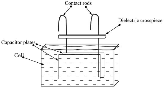
Figure 1.
Set-up for determining the dielectric constant of liquids.
The cell was filled with the liquid under study, and the capacitance of this capacitor, completely immersed in the liquid, was measured at a frequency of ~4.4 MHz, corresponding to the operating frequency of the resonator. It was assumed that the capacitance of such a capacitor is proportional to the dielectric constant of the liquid. Using the known dielectric constant of water (εl = 80), the dielectric constant of all mixtures was determined.
2.2. Description of a Quartz Resonator and Methods for Measuring Its Parameters
The selected resonator based on the quartz plate of AT- or YXl/+35°-cut (Euler angles = 0, 0, 35°) for studying liquids had a plate thickness of 370 µm and electrode diameter of 5.8 mm. The electrode material is a complex silver-based alloy. This cut of quartz is characterized by a low-temperature delay coefficient for the shear acoustic mode excited in this resonator. The quality factor of the parallel resonance of the unloaded resonator turned out to be quite high (Q = 1,300,000), which indicates an insignificant roughness of the quartz surface and electrodes, as well as a high degree of plane-parallelism of the faces [28]. To carry out the experiments, the resonator was fixed into the bottom of a 30 mL plastic container (Figure 2).
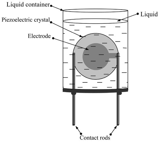
Figure 2.
The liquid container with the quartz resonator.
First, the frequency dependences of the real and imaginary parts of the electrical impedance of the free resonator were measured using an E4990A impedance analyzer (Keysight Technologies, Santa Rosa, CA, USA). Then, the container was filled with the liquid sample under study so that the resonator was completely immersed in the liquid, and the measurement of the above frequency dependences was repeated. Each liquid sample, immediately before measurement, was stirred on a magnetic stirrer for one hour. The temperature in the room with measuring equipment was maintained within 25–27 °C.
2.3. The Influence of the Test Liquid on the Characteristics of a Quartz Resonator
The main characteristics of piezoelectric resonators include the values of the resonant frequency of the parallel and series resonances and the maximum values of the real parts of the electrical impedance and admittance [20,27]. It is well known that these characteristics strongly depend on the electrical and mechanical parameters of contacting liquid [16,20,23,24,25,26,27]. Figure 3 shows the dependences of the frequency of the parallel Fpar (a) and serial Fser (b) resonances and the maximum values of the electrical impedance Rmax (c) and admittance Gmax (d) on the conductivity of the contacting liquid at the various concentration of glycerol.
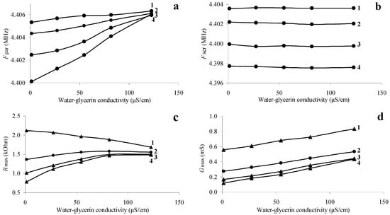
Figure 3.
Dependences of the resonant frequency of parallel (a) and series (b) resonances, as well as the maximum values of the real parts of the electrical impedance (c) and admittance (d) of a quartz resonator on the conductivity of the liquid. (1—aqueous solution of sodium chloride (β = 0), 2—mixture “water-glycerol” β = 44%, 3—mixture “water-glycerol” β = 65%, 4—mixture “water-glycerol” β = 75%).
The dependences presented in Figure 3 show that with an increase in the conductivity of the liquid from 1.4 to 123 μS/cm, the parallel resonance frequency of the quartz resonator monotonically increases for all “water–glycerol” mixtures. This result is in full qualitative agreement with the data of [26], where the theoretical and experimental dependences of the parallel resonance frequency shift on the conductivity of the contacting liquid are presented. Figure 3d shows that the maximum value of the electrical admittance also increases monotonically with increasing conductivity. With an increase in the conductivity of an aqueous solution of sodium chloride (Figure 3c, curve 1), the maximum value of the real part of the electrical impedance decreases, and for mixtures of “water–glycerol” (Figure 3c, curves 2–4), it increases. In this case, the resonant frequency of the series resonance (Figure 3b) depends only on the concentration of glycerol (viscosity) and practically does not change with changes in the conductivity of the liquid [23,24,25].
Figure 3a,b,d allowed plotting the dependences of the frequency of the parallel Fpar and serial Fser resonances and the maximum value of the real part of the electrical admittance Gmax on the measured magnitude of the liquid viscosity at different values of its conductivity. These dependences are presented in Figure 4. One can see that Fpar monotonically decreases with increasing viscosity, which is in qualitative agreement with the results of [23,24,25,26]. At that, the increase of the viscosity monotonically reduces the value of Gmax. Figure 4b shows that with increasing the viscosity, Fser reduces monotonically and does not depend on conductivity [23,24,25]. Thus, Figure 4b can be considered a calibration curve for determining the viscosity from the measured value of the resonant frequency Fser. Figure 4a, in turn, allows us to find the conductivity of the liquid from the measured value of the parallel resonance frequency Fpar and the found viscosity value.
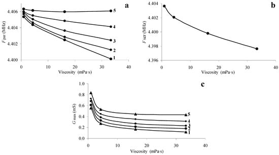
Figure 4.
Dependences of the resonant frequency of parallel (a) and series (b) resonances, as well as the maximum values of the real parts of the electrical admittance (c) of a quartz resonator on the viscosity of the liquid. Liquid conductivity: 1—1.4 μS/cm, 2—27 μS/cm, 3—55 μS/cm, 4—82 μS/cm, 5—123 μS/cm.
2.4. Determination of Material Constants of a Resonator Using an Equivalent Circuit
For the calculation of the frequency dependencies of the electrical impedance of a piezoelectric resonator without liquid loading, we used the method based on the equivalent electromechanical scheme of Mason [29]. Since this method is described in detail in [27], we provide only brief information here. Using the equivalent scheme of Mason and the pointed above method, the frequency dependences of the real and imaginary parts of the electric impedance of the free resonator were calculated. We used the orthogonal coordinate system corresponding to the AT cut of the quartz: the X1 axis is normal to the surface of the plate and determines the direction of the propagation of the wave, and the X2 axis is parallel to the vector of polarization of the wave. In this case, the quartz is described by the elastic module C66, viscosity coefficient η66, piezoconstant e16 and permittivity ε11 in the indicated coordinate system. As for the material of the electrodes, we will assume that it is isotropy, and the elastic module and viscosity coefficient can be represented as C66e and η66e.
In this calculation, the above-pointed material constants of quartz and electrodes were taken from the literary sources [27]. Then, in order to determine the true material constant of quartz and electrodes, the calculated frequency dependences of the real and imaginary parts of the electrical impedance were fitted to the experimental ones.
By trying all the unknown constants, C66, η66, e16 and ε11 of quartz, using the method of the smallest squares, such a combination was determined, for which theoretical frequency dependences of the real (R) and imaginary (X) parts of the resonator’s electrical impedance were most consistent with experimental ones (Figure 5). Table 1 presents the initial (reference) [27] and the values obtained as a result of fitting.
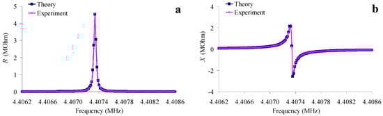
Figure 5.
The frequency dependences of the real (a) and imaginary (b) parts of the electrical impedance of the AT-quartz resonator without load (pink—experiment, blue—the result of fitting).

Table 1.
Initial (reference) and resulting from the fitting values of the material constants of the quartz resonator AT-cut.
2.5. Determination of Material Constants of the Liquids Using an Equivalent Electromechanical Circuit
Figure 6 shows an equivalent electromechanical circuit describing a piezoelectric resonator with a longitudinal electric field completely immersed in a viscous conducting liquid. The mechanical contact of the resonator with a liquid is described by the complex impedance Zl. The dielectric constant and electrical conductivity of the liquid are taken into account by including in the electrical part of the circuit the additional capacitance Ca and additional resistance Ra, respectively. For a liquid, the mechanical impedance Zl and the acoustic wave velocity υl can be represented as follows [29]:
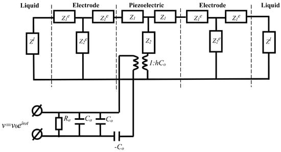
Figure 6.
Equivalent circuit of a resonator with electrodes immersed in a liquid, taking into account additional capacitance (Ca) and resistance (Ra).
Zl = izlS,
υl = {(C66l + iωη66l)/ρl}1/2,
zl = {(C66l + iωη66l)ρl}1/2.
Here, zl is the specific mechanical impedance of the liquid, C66l is the shear module of elasticity of the liquid, η66l is the shear viscosity coefficient, ρl is the density of the liquid, S is the area of the electrodes, i is the imaginary unit. The subscript l indicates that the quantity belongs to the liquid.
According to the method described in [27], such a set of the pointed quantities, C66l, η66l, Ca and Ra, was determined, for which the theoretical frequency dependences of the real (R) and imaginary (X) parts of the electrical impedance of the resonator immersed in the liquid corresponded as much as possible to the experimental ones. In the calculations, we used the constants of the piezoelectric material and electrodes obtained earlier in Section 2.4. As an example, Figure 7 shows the theoretical and experimental frequency dependences of the real (R) and imaginary (X) parts of the electrical impedance of a quartz resonator immersed in an aqueous solution of NaCl with a conductivity of 1.4 μS/cm (Figure 7a,b) and in a “water–glycerol” mixture (β = 75%, σl = 55 μS/cm) (Figure 7c,d). There is a good agreement between the theory and experiment, and the maximum differences are equal to 6.8% and 2.4% for the real and imaginary parts of the impedance, respectively.
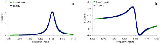
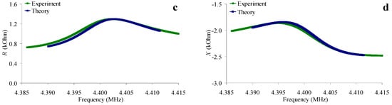
Figure 7.
Frequency dependences of the real (a,c) and imaginary (b,d) parts of the electrical impedance of a quartz resonator for an aqueous solution of NaCl with a conductivity of 1.4 μS/cm (a,b), and for a “water–glycerol” mixture β = 75%, σl = 55 μS/cm (c,d). Blue color—theory, green color—experiment.
3. Results
Table 2 shows the full data on the liquid samples under study. The first four columns indicate the liquid parameters that were directly measured according to the procedures described in 2.1. These are the percentage of glycerol (β), dielectric constant (εl), density (ρl), specific conductivity (σl) and shear viscosity measured using a viscometer (η66ll). The following columns contain the quantities found using the equivalent circuit of the resonator. These are the shear elastic module (C66l), shear viscosity coefficient (η66l), shear acoustic wave velocity (v66l), additional capacitance (Ca) and additional resistance (Ra), respectively.
Table 2.
The parameters of liquid samples under study: the percentage of glycerol (β), dielectric constant (εl), density (ρl), specific conductivity (σl), shear viscosity measured by a viscometer (η66ll), shear elastic module (C66l), shear coefficient of viscosity (η66l), shear acoustic wave velocity (v66l), additional capacitance (Ca) and resistance (Ra).
From Table 2, one can see that in all cases, the shear viscosity value obtained using Mason’s scheme exceeds the value measured by a viscometer. This is due to the fact that in Mason’s scheme, viscosity describes all the losses that exist in the liquid. These include dielectric and thermoelastic losses, absorption associated with the intrinsic viscosity of the fluid, and acoustic wave scattering associated with the roughness of the resonator surface. The maximum difference in the values of the effective and true viscosity varies from 35% to 6% as the viscosity increases. This is explained by the fact that as viscosity increases, the proportion of the loss associated specifically with the true viscosity of the liquid increases in comparison with other sources of loss. In this case, the spread of viscosity values depending on the conductivity changes from 20% to 3% with increasing the viscosity obtained as a result of fitting the theory to the experiment.
Table 2 also shows that the shear viscosity coefficient η66l, the velocity of the shear acoustic wave υ66l and the additional capacitance Ca slightly depend on the conductivity of the liquid. In this case, with increasing concentration of glycerol in water, the shear viscosity coefficient η66l and the velocity of the shear acoustic wave υ66l increase, and the additional capacity Ca decreases. The additional resistance Ra of a resonator immersed in a liquid decreases with increasing the liquid conductivity for all four types of liquids.
Based on the data presented in Table 2, the dependences of the additional capacity Ca on the conductivity of the liquid were constructed for various values of the volume concentration of glycerol. They are shown in Figure 8a. It can be seen that this capacity is practically independent of the conductivity of the liquid and decreases with increasing the glycerol concentration. The additional capacity Ca is an addition to the capacitance of the free resonator C0 due to the permittivity of the contacting liquid. With increasing the glycerol concentration, the permittivity of the mixture decreases from 81 to 57, and this leads to a decrease in the capacity Ca. This is confirmed in Figure 8b, which shows the dependence of the average value of additional capacity <Ca> on the measured relative dielectric constant εl. Averaging was carried out for all conductivity values for each glycerol concentration. One can see that this capacity increases monotonically with increasing liquid permittivity. Therefore, the dependence presented in Figure 8b may be used as a calibration curve to determine the liquid permittivity from the calculated value of the additional capacity.
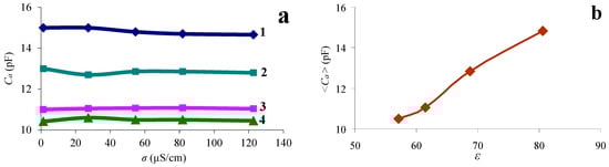
Figure 8.
(a)—dependence of the additional capacity Ca on the conductivity of the liquid with different percentages of glycerol: 1—water, 2—mixture “water–glycerol” β = 44%, 3—mixture “water–glycerol” β = 65%, 4—mixture “water–glycerol” β = 75%. (b)—dependence of the average value of the additional capacity <Ca> on the measured value of εl.
It is obvious that when the resonator is completely immersed in liquid, the resonator electrodes are shunted by both an additional capacitance Ca (due to the dielectric constant) and an additional active resistance Ra (due to its conductivity). In the equivalent circuit, these elements are connected to the electrical input parallel to the resonator capacitance C0. Using the data given in Table 2, the dependence of the additional resistance Ra on the conductivity σl of the liquid was constructed. This dependence is shown in Figure 9. It can be seen that this resistance is practically independent of the volumetric content of glycerol (that is, on viscosity and permittivity) and monotonically decreases with increasing conductivity of the liquid. Therefore, this dependence can be used as a calibration curve to determine the conductivity σl of a liquid from the calculated value Ra.
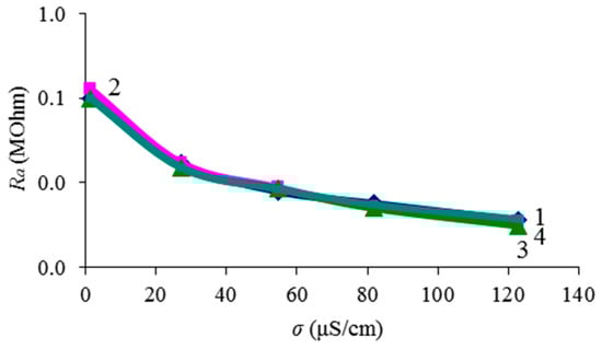
Figure 9.
Dependence of the additional resistance Ra on the conductivity of a liquid with different percentages of glycerol: 1—water, 2—water–glycerol mixture β = 44%, 3—water–glycerol mixture β = 65%, 4—water–glycerol mixture β = 75%.
4. Discussion
The measured frequency dependences of the real and imaginary parts of the electrical impedance of the quartz resonator completely immersed in the liquid allowed us to obtain the frequencies of parallel and serial resonances and the maximum values of the electrical impedance and admittance as functions of the liquid conductivity with different viscosities. These data allow us to find the values of the viscosity and conductivity of the liquid. To determine other material constants, such as shear elastic module and permittivity with the help of a quartz resonator with a longitudinal electric field, we used measured frequency dependences of the real and imaginary parts of the electrical impedance of a free resonator and a resonator completely immersed in the liquid under study. For this, an equivalent electromechanical circuit of Mason was used. For the equivalent circuit for a resonator completely immersed in a liquid, in addition to the electromechanical transformer and the standard electrical and mechanical parts of the circuit, we also included liquid loading in the mechanical part and additional capacitance and additional resistance in the electrical part. The additional capacitance and additional resistance were included due to the permittivity and conductivity of the liquid. The material constants and also additional capacitances and resistances were determined by fitting the theoretical frequency dependences of the real and imaginary parts of the electrical impedance of the resonator, calculated using an equivalent circuit, to the experimentally measured ones. As a result, the shear elastic module, viscosity coefficient, and relative dielectric constant, as well as values of the additional capacitance and additional resistance of the resonator loaded by liquids with different viscosities and conductivities, were obtained. An increase in the concentration of glycerol in water leads to an increase in the shear viscosity coefficient and the velocity of the shear acoustic wave and to a decrease in the additional capacity. Table 2 shows that the additional capacitance of a resonator immersed in a conducting liquid weakly depends on the conductivity of the liquid. The value of this quantity, averaged over all conductivity values for each type of liquid, increases with increasing experimentally determined relative dielectric constant. The amount of additional resistance decreases with increasing liquid conductivity in all cases.
5. Conclusions
Thus, the results obtained allow us to develop an algorithm for measuring the electrical and mechanical parameters of a liquid using a piezoelectric resonator with a longitudinal electric field. The measured dependences of the frequencies of parallel and serial resonances, as well as the maximum value of the real part of the electrical admittance on the viscosity of the liquid at different values of the conductivity, can be considered calibration curves for a given resonator. Therefore, we can propose the following algorithm for determining fluid parameters. (1) First, the frequency dependences of the real and imaginary parts of the electrical impedance of the free (unloaded with liquid) resonator are measured, and by fitting the theoretical dependences to the experimental ones, the characteristics of all elements of the Mason equivalent circuit are determined. (2) Then, the specified frequency characteristics of the resonator, completely immersed in the test liquid, are measured. (3) Based on the measured values of the resonant frequency of the series resonance, the viscosity of the liquid may be found according to the dependence in Figure 4b. (4) Based on the measured value of the parallel resonance frequency and liquid viscosity using the calibration curve in Figure 4a, the conductivity of the liquid is defined. (5) By fitting the theoretical frequency dependences of the real and imaginary parts of the electrical impedance of the loaded resonator to the experimental ones, the elastic module and permittivity of the liquid are determined.
Author Contributions
Conceptualization, A.S. and B.Z.; methodology, A.S. and B.Z.; software, A.S.; validation, A.T., A.S. and B.Z.; formal analysis, A.S.; investigation, A.S. and B.Z.; resources, I.B.; data curation, I.B.; writing—original draft preparation, A.S. and B.Z.; writing—review and editing, B.Z. and I.B.; visualization, B.Z.; supervision, B.Z.; project administration, I.B.; funding acquisition, I.B. All authors have read and agreed to the published version of the manuscript.
Funding
This work is financially supported by the grant of Russian Scientific Foundation # 23-22-00134.
Institutional Review Board Statement
Not applicable.
Informed Consent Statement
Not applicable.
Data Availability Statement
Data are contained within the article.
Conflicts of Interest
The authors declare no conflicts of interest.
References
- Arlett, J.L.; Myers, E.B.; Roukes, M.L. Comparative advantages of mechanical biosensors. Nat. Nanotechnol. 2011, 6, 203–215. [Google Scholar] [CrossRef]
- Lin, Q.; Cai, F.; Li, F.; Zhao, D.; Xia, X.; Zhou, W.; Meng, L.; Zheng, H. The compact acoustic liquid sensor based on the circumferential modes of a cylindrical shell. Sens. Actuators A 2020, 304, 111843. [Google Scholar] [CrossRef]
- Zaitsev, B.D.; Joshi, S.G.; Kuznetsova, I.E.; Borodina, I.A. Acoustic waves in piezoelectric plates bordered with viscous and conductive liquids. Ultrasonics 2001, 39, 45–50. [Google Scholar] [CrossRef]
- Anisimkin, I.V.; Anisimkin, V.I. Attenuation of acoustic normal modes in piezoelectric plates loaded by viscous liquids. IEEE Trans. Ultrason. Ferroelectr. Freq. Control 2006, 53, 1487–1492. [Google Scholar] [CrossRef]
- Anisimkin, V.I. Sensing properties of the Anisimkin Jr. acoustic modes in uncoated ST-quartz plates. IEEE Trans. Ultrason. Ferroelectr. Freq. Control 2013, 60, 2204–2207. [Google Scholar] [CrossRef] [PubMed]
- Wu, J.; Zhu, Z. Sensitivity of Lamb wave sensors in liquid sensing. IEEE Trans. Ultrason. Ferroelectr. Freq. Control 2002, 43, 71–72. [Google Scholar]
- Anisimkin, V.I.; Voronova, N.V. New modification of the acoustic Lamb waves and its application for liquid and ice sensing. Ultrasonics 2022, 116, 106496. [Google Scholar] [CrossRef] [PubMed]
- Caliendo, C.; Hamidullah, M. Guided acoustic wave sensors for liquid environments. J. Phys. D Appl. Phys. 2019, 52, 153001. [Google Scholar] [CrossRef]
- Voronova, N.V.; Anisimkin, V.I. Three-Parameter Liquid Sensor Based on Surface and Plate Acoustic Waves. In Proceedings of the 2017 Joint Conference of the European Frequency and Time Forum and IEEE International Frequency Control Symposium, Besancon, France, 9–13 July 2017; pp. 343–344. [Google Scholar] [CrossRef]
- Kondoh, J.; Shiokawa, S. SH-SAW taste sensor based on acoustoelectric interaction. In Proceedings of the 1993 IEEE International Ultrasonics Symposium, Baltimore, MD, USA, 31 October–3 November 1993; pp. 421–424. [Google Scholar]
- Kondoh, J.; Shiokawa, S. New application of shear horizontal surface acoustic wave sensors to identifying fruit juices. Jpn. J. Appl. Phys. 1994, 33, 3095–3099. [Google Scholar] [CrossRef]
- Kondoh, J.; Muramatsu, T.; Nakanishi, T.; Shiokawa, S. Development of surface acoustic wave liquid sensing system and application for Japanese tea measurements. In Proceedings of the 2001 IEEE International Ultrasonics Symposium, Atlanta, GA, USA, 7–10 October 2001; pp. 497–501. [Google Scholar]
- Kondoh, J.; Nakayama, K.; Kuznetsova, I. Study of frequency dependence of shear horizontal surface acoustic wave sensor for engine oil measurement. Sens. Actuators A Phys. 2021, 325, 112503. [Google Scholar] [CrossRef]
- Tada, K.; Nozava, T.; Kondoh, J. Real time monitoring of methanol concentration using a shear horizontal surface acoustic wave sensor for direct methanol fuel cell without reference liquid. Jap. J. Appl. Phys. 2016, 37, 07JD15. [Google Scholar] [CrossRef]
- Vetelino, J.F. A lateral field excited acoustic wave sensor platform. In Proceedings of the 2010 IEEE International Ultrasonics Symposium, San Diego, GA, USA, 11–14 October 2010; pp. 2269–2272. [Google Scholar]
- McCann, D.F.; McCann, J.M.; Parks, J.M.; Frankel, D.J.; Pereira da Cunha, M.; Vetelino, J.F. A lateral-field-excited LiTaO3 high frequency bulk acoustic wave sensor. IEEE Trans. Ultrason. Ferroelectr. Freq. Control 2006, 56, 779–787. [Google Scholar] [CrossRef]
- Wark, M.; Kalanyan, B.; Ellis, L.; Fick, J.; Connel, L.; Neivandt, D.; Vetelino, J. A lateral field excited acoustic wave sensor for the detection of saxitoxin in water. In Proceedings of the 2007 IEEE International Ultrasonics Symposium, New York, NY, USA, 28–31 October 2007; pp. 1217–1220. [Google Scholar]
- French, L.A., Jr.; FitzGerald, M.; Vetelino, J.F. An Equivalent Circuit Model for a Liquid Loaded Lateral-Field Excited Acoustic Wave Sensor. In Proceedings of the 2011 IEEE International Ultrasonics Symposium, Orlando, FL, USA, 19 October 2011; pp. 1194–1199. [Google Scholar]
- Ma, T.; Wang, J.; Du, J.; Yuan, L.; Qian, Z.; Zhang, Z.; Zhang, C. Lateral-field-excited bulk acoustic wave sensors on langasite working on different operation modes. IEEE Trans. Ultrason. Ferroelectr. Freq. Control 2013, 60, 864–867. [Google Scholar] [CrossRef] [PubMed]
- Zaitsev, B.D.; Shikhabudinov, A.M.; Teplykh, A.A.; Kuznetsova, I.E. Liquid sensor based on a piezoelectric lateral electric field-excited resonator. Ultrasonics 2015, 63, 179–183. [Google Scholar] [CrossRef]
- Wang, M.; Shi, H.; Ma, T.; Qian, Z.; Kuznetsova, I.; Yuan, L.; Wang, J.; Du, J.; Zhang, C. High-frequency vibration analysis of LiTaO3 piezoelectric plates excited by lateral electric fields produced by surface electrodes under viscous liquid loadings for sensing. Smart Mater. Struct. 2020, 29, 045004. [Google Scholar] [CrossRef]
- Zaitsev, B.D.; Borodina, I.A.; Teplykh, A.A. Compact liquid analyzer based on a resonator with a lateral excitation electric field. Ultrasonics 2022, 126, 106814. [Google Scholar] [CrossRef]
- Kanazava, K.K.; Gordon, J.G., II. The oscillation frequency of a quartz resonator in contact with a liquid. Anal. Chim. Acta 1985, 175, 99–105. [Google Scholar]
- Kanazava, K.K.; Gordon, J.G., II. Frequency of a Quartz Microbalance in Contact with Liquid. Anal. Chem. 1985, 57, 1770–1771. [Google Scholar] [CrossRef]
- Nomura, T.; Watanabe, M.; West, T.S. Behavior of piezoelectric quartz crystals in solutions with the applications to the determination of iodide. Anal. Chim. Acta 1985, 175, 107–116. [Google Scholar] [CrossRef]
- Josse, F.; Shana, Z.A.; Radtke, D.E.; Haworth, D.T. Analysis of piezoelectric bulk acoustic wave resonators as detectors in viscous conductive liquids. IEEE Trans. Ultrason. Ferroelectr. Freq. Control 1990, 37, 359–368. [Google Scholar] [CrossRef]
- Semyonov, A.; Zaitsev, B.; Teplykh, A.; Borodina, I. The effect of the glycerol—Based suspension on the characteristics of resonators excited by a longitudinal electric field. Sensors 2023, 23, 608. [Google Scholar] [CrossRef] [PubMed]
- Vig, J.R. Quartz Crystal Resonators and Oscillators for Frequency Control and Timing Applications—A Tutorial; US Army Communications-Electronics Research; Development & Engineering Center Fort Monmouth: Fort Monmouth, NJ, USA, 2004. [Google Scholar]
- Royer, D.; Dieulesaint, E. Elastic Waves in Solids II Generation, Acousto-Optic Interaction, Applications; Springer: Berlin/Heidelberg, Germany; New York, NY, USA, 1999; ISBN 1439-2674. [Google Scholar]
Disclaimer/Publisher’s Note: The statements, opinions and data contained in all publications are solely those of the individual author(s) and contributor(s) and not of MDPI and/or the editor(s). MDPI and/or the editor(s) disclaim responsibility for any injury to people or property resulting from any ideas, methods, instructions or products referred to in the content. |
© 2024 by the authors. Licensee MDPI, Basel, Switzerland. This article is an open access article distributed under the terms and conditions of the Creative Commons Attribution (CC BY) license (https://creativecommons.org/licenses/by/4.0/).