2.1. Speck-R Enhanced
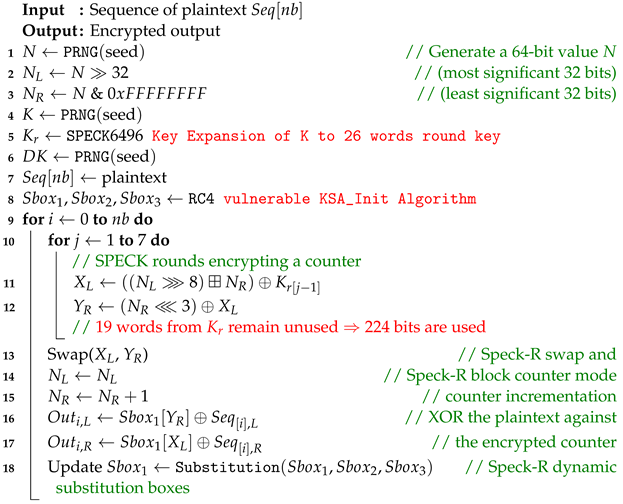
In order to secure communication over the unidirectional fiber optic link, the Speck-R [
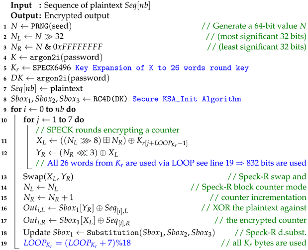
39] ultra-lightweight cipher summarized in Algorithm 1 has been modified as shown in Algorithm 2.
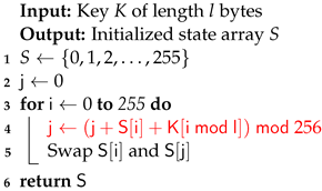
The RC4 vulnerable key scheduler [
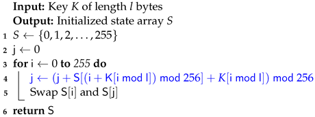
40] in Algorithm 3 has been replaced with the secure RC4D [
41] version from Algorithm 4. RC4 weak keys and other vulnerabilities have been studied for a long time, making RC4 a suboptimal choice for use in Speck-R [
42,
43,
44,
45].
The enhanced Speck-R substitution boxes generated using RC4D [
41] are a password-depending secret. Line 8 in Algorithm 2 shows that a hash of the password is used in order to initialize the algorithm. Ciphers with known substitution boxes as Speck-R [
39], or those that do not require substitution boxes at all, like Simeck-Tea [
46] or SIMON and SPECK [
47], are lighter on resources but may not provide the same level of security.
The main idea behind Speck-R [
39] is that a reduced number of ordinary SPECK [
47] rounds shown in lines 10–12 are followed by a dynamic substitution boxes routine in line 18, where 3 susbtitution boxes are interchanged depending on the block count. These boxes are initially configured with the RC4 Algorithm 3. Another particularity of Speck-R is the swap used in the process of counter incrementation—line 13 in Algorithms 1 and 2. Swapping two 32-bit words from the 64-bit counter followed by an increment in the right part makes sure that the ciphertext is more scrambled.
The variable introduced in Algorithm 2 ensures that the full 26 words of the expanded rounds key are used when encrypting multiple 64-bit blocks using an encryption key size of 96 bits.
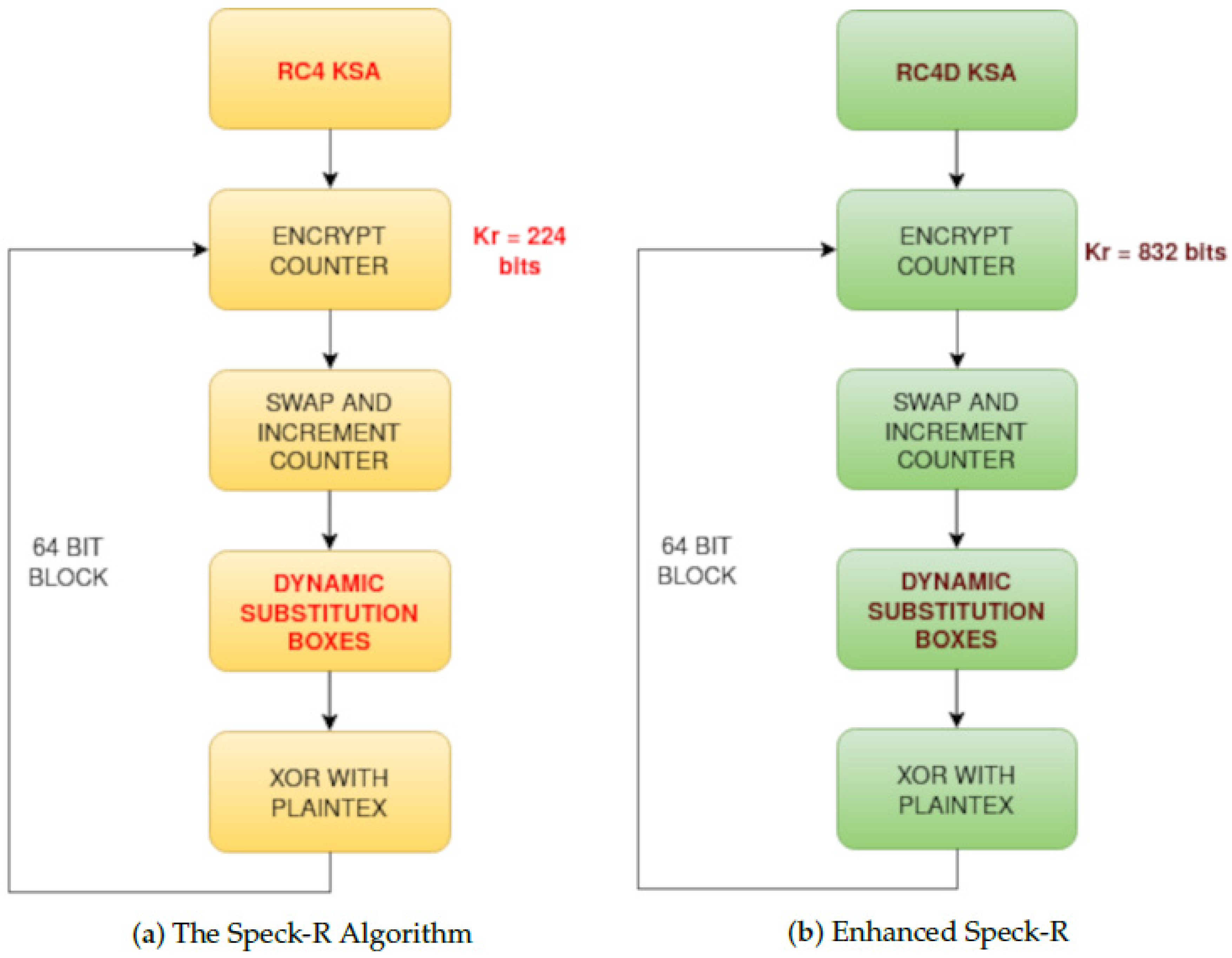
Figure 2 emphasizes another modification in the enhanced version of Speck-R, where a round key of 832 bits is used in
Figure 2b instead of a truncated 56-bit rounds key in
Figure 2a.
| Algorithm 1: The encryption process of Speck-R from [39] with vulnerable KSA_Init [42,43,44,45]. |
![Sensors 24 06537 i001 Sensors 24 06537 i001]() |
| Algorithm 2: Our Enhanced Encryption process of Speck-R implemented in [48] with secure KSA_Init [41]. |
![Sensors 24 06537 i002 Sensors 24 06537 i002]() |
| Algorithm 3: RC4 Key Scheduling Algorithm [40] used by Speck-R [39]. |
![Sensors 24 06537 i003 Sensors 24 06537 i003]() |
| Algorithm 4: RC4D Key Scheduling Algorithm [41] used by Enhanced Speck-R. |
![Sensors 24 06537 i004 Sensors 24 06537 i004]() |
2.2. Data Diode Configuration
A data diode effectively drops any packet flowing in the wrong direction. A hardware data diode like those made of fiber optics simply does not present a backward communication channel. The GNU/Linux operating system is used with static arp [
49] configured correctly on both sides of the data diode.
The medium access control address (MAC) is a unique identifier assigned to a network interface controller [
50]. On Debian-based distributions, the arp tool is located in the net-tools package, which must be installed:
apt update
apt install net-tools
On host A, the IP address and the MAC address of the side B network card are added in the /etc/ethers file:
/etc/ethers (on side A):
bb:bb:bb:bb:bb:bb 192.168.10.2
On host B, the IP address and the MAC of the side A network card are added in the /etc/ethers file:
/etc/ethers (on side B):
aa:aa:aa:aa:aa:aa 192.168.10.1
On a bidirectional connection, these settings can be communicated freely between hosts, but on a unidirectional link, the MAC address information must be configured by the user.
The two network cards must be configured with IP addresses that are part of the same network.
For host A:
sudo ip addr add 192.168.10.1/24 dev enp1s0
For host B:
sudo ip addr add 192.168.10.2/24 dev enp1s0
If any network manager is running in the background, it can be disabled to avoid configuration interference; otherwise, the static IP address and the network mask must match.
The /etc/ethers file has to be loaded at boot time using the “arp -f /etc/ethers” command. Older distributions that use SysVinit will start all system services defined in scripts under /etc/init.d/, and then will end up running /etc/rc.local. This file may be edited to run the following:
/etc/rc.local:
/usr/sbin/arp -f /etc/ethers
and permissions should allow for the execution of
chmod +x /etc/rc.local
In order to create rc.local compatibility with systemd distributions, a systemd service unit must be created:
sudo nano /etc/systemd/system/rc-local.service
containing the following lines:
[Unit]
Description=Run script after network (on boot)
ConditionPathExists=/etc/rc.local
After=network.target
[Service]
Type=forking
ExecStart=/etc/rc.local
TimeoutSec=0
StandardOutput=tty
RemainAfterExit=yes
[Install]
WantedBy=multi-user.target
The service will start at boot but it has to be enabled:
sudo systemctl enable rc-local
and it can also be started immediately using the following command:
sudo systemctl start rc-local
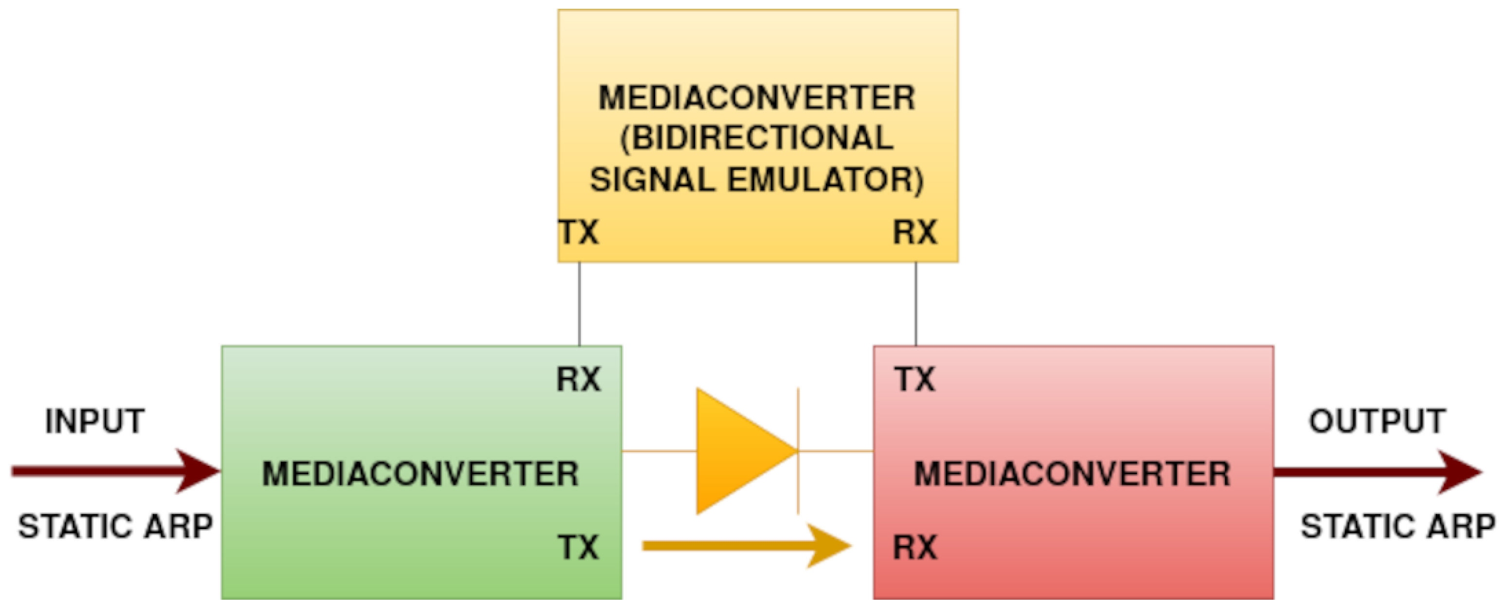
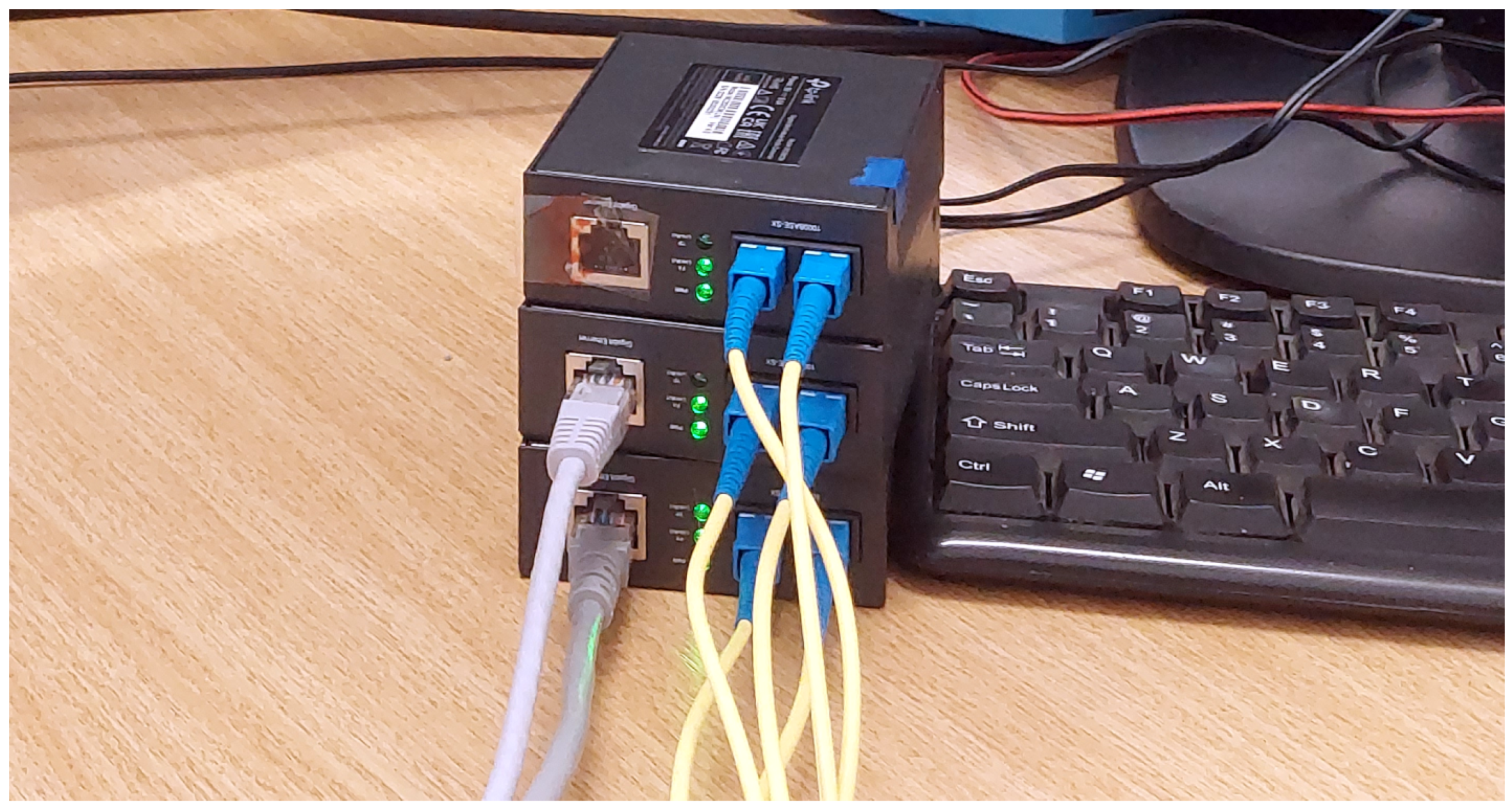
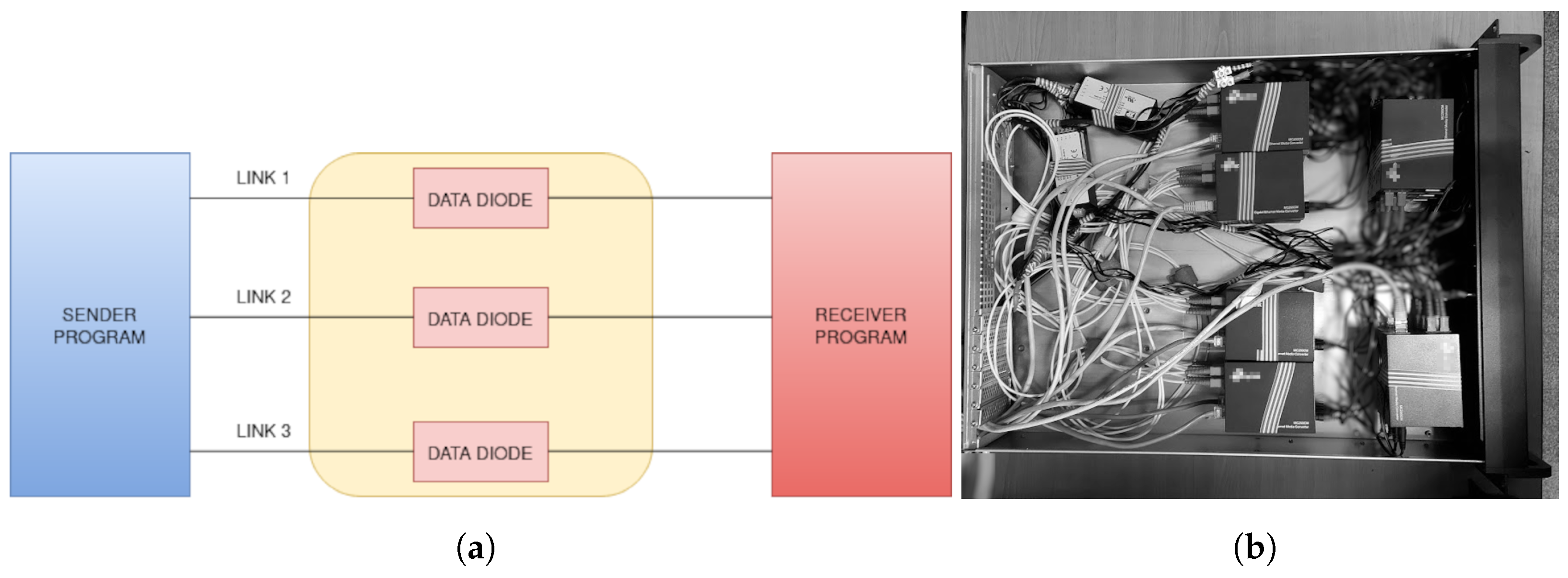
Figure 3 describes the connection schematics of a data diode made of gigabit ethernet media converters. Each of the media converters also shown in
Figure 4 has separate ports for transmission (TX) and reception (RX).
Fiber optic cables are connected from (TX) to (RX), but one of the media converters is placed between the other two (on top in
Figure 4), making sure that the port (RX) from the input of the data diode will detect an on-line signal but will always remain disconnected from the output of the data diode.
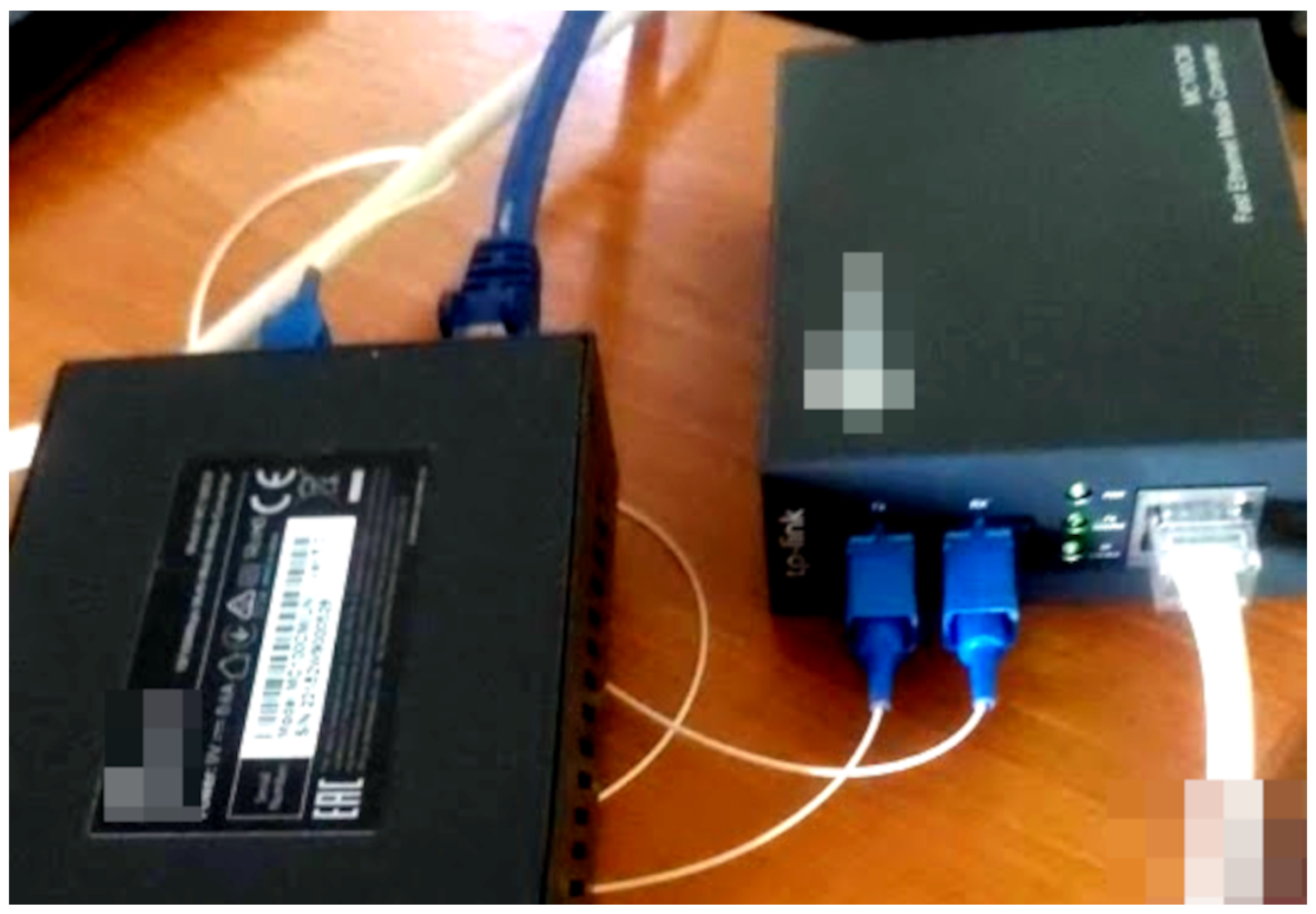
Figure 5 shows the schematics of a fast ethernet data diode made of 2 TP-Link MC100CM media converters (Shenzen, China).
A fiber optic splitter is also visible in
Figure 6 as a white cable with 2 sockets on one side and 1 socket on the other. It was used to copy the light signal back to the transmitter media converter.
This approach did not work for TP-Link MC200CM (Kowloon, Hong Kong) gigabit ethernet media converters shown in
Figure 3 and
Figure 4. In this case, the third media converter was used to emulate the light signal for the transmitter. The connection between the output media converter and the signal emulator is necessary in order to keep the signal emulator running.
The quality of the cable splitter influences the strength of the light signal over the fiber optic return path link. If the signal is too low at the (RX) port, the sender media converter may not detect an online connection. In addition, some protection schemes might simply prevent such configurations on more recent products.
2.3. Proposed Solution
The proposed framework consists of two main components: a syslog collector–sender, which encrypts and transmits syslog messages multiple times to ensure delivery, and a syslog receiver–forwarder, which deduplicates, decrypts, and forwards the messages to a rsyslog server [
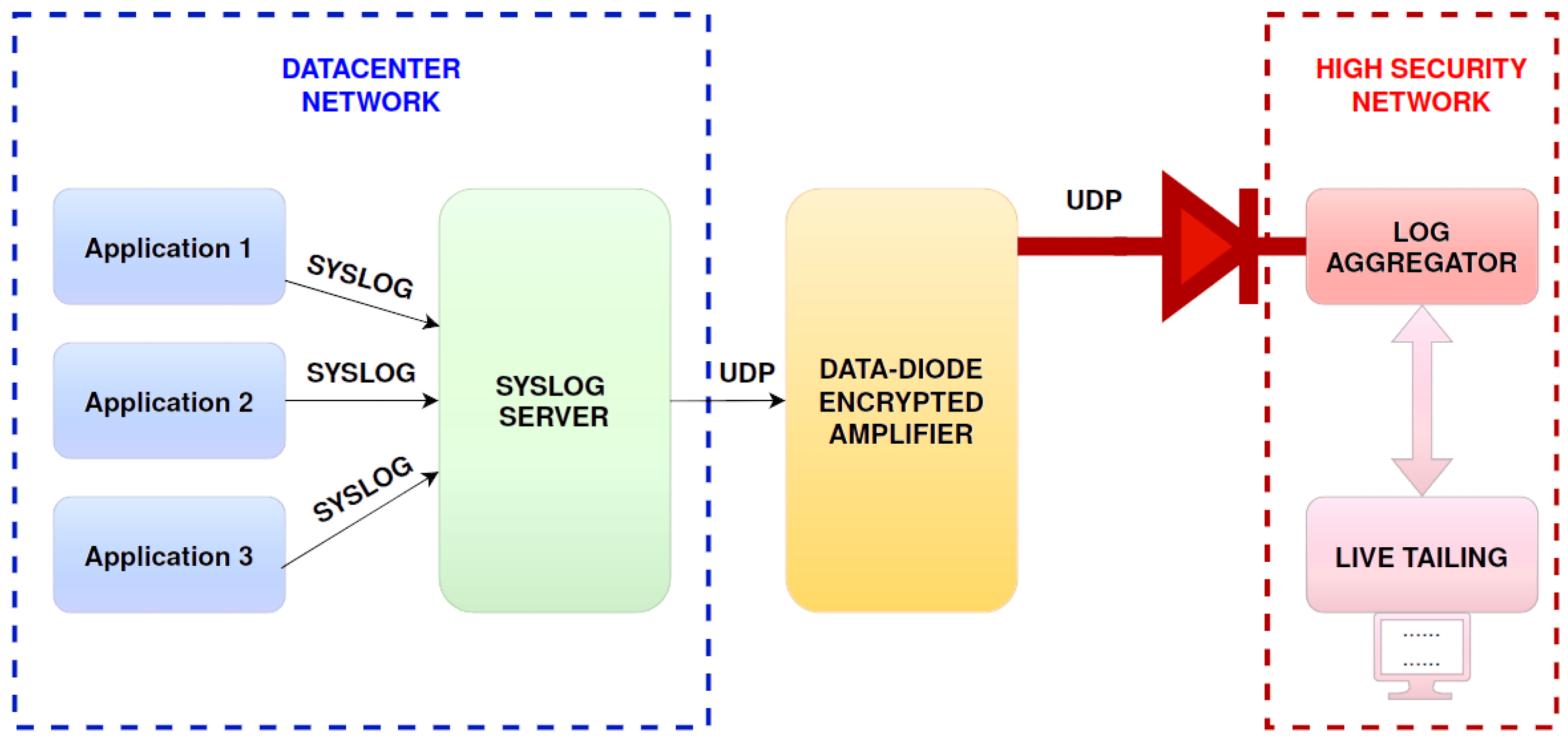
51]. The proposed solution is shown in
Figure 7.
Several applications and devices are sending syslog messages to a syslog server residing on a network. The syslog server encrypts and boosts these messages by sending them in a repeated manner over a UDP protocol through a data diode. The data diode connects the logging network with a higher-security network in a unidirectional way. Incoming messages are filtered in a log aggregator to eliminate duplicates and decrypt them back to their original form. This high-security network allows for the live tailing and further monitoring of the information provided from outside the security level. This is basically a classic Bell–LaPadula security model (BLM), where the low network cannot read from the high network [
52]. The storage devices in the high network can be of the write-once read-many (WORM) types such that log tampering is impossible even from the high network by mistake.
To summarize the Bell–LaPadula confidentiality concept, which also involves a BIBA integrity model (BIM) in
Figure 7, no user in the low-security level network may read or modify information stored in the high-security level network [
52]. This, of course, has to do with logs at rest. For data in transit, bogus devices can still send any kind of information that they want and can even try to replay logs sent by other devices. Replaying can be detected by the decryption process because the resulting text line will not contain only printable characters from the ASCII table but the authenticity and validity of the logged information will remain unknown and highly depend on the security of the devices and systems in the data center network themselves.
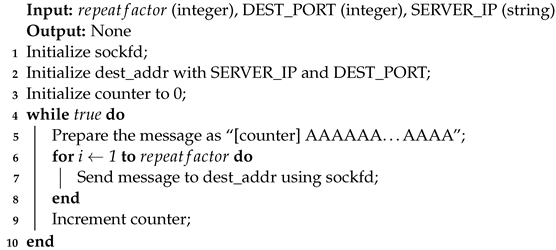
The message format for the logs that will be encrypted and boosted on the data diode is shown in
Figure 8. A 64-bit counter is inserted as a prefix before encryption. This counter is to be removed prior to decryption. Inserting a fake counter by bogus devices is not possible since only the first 64 bits are going to be interpreted as a counter and this counter is always inserted by the sender. This is why a replayed message will have a bogus counter and decryption will result in garbage.
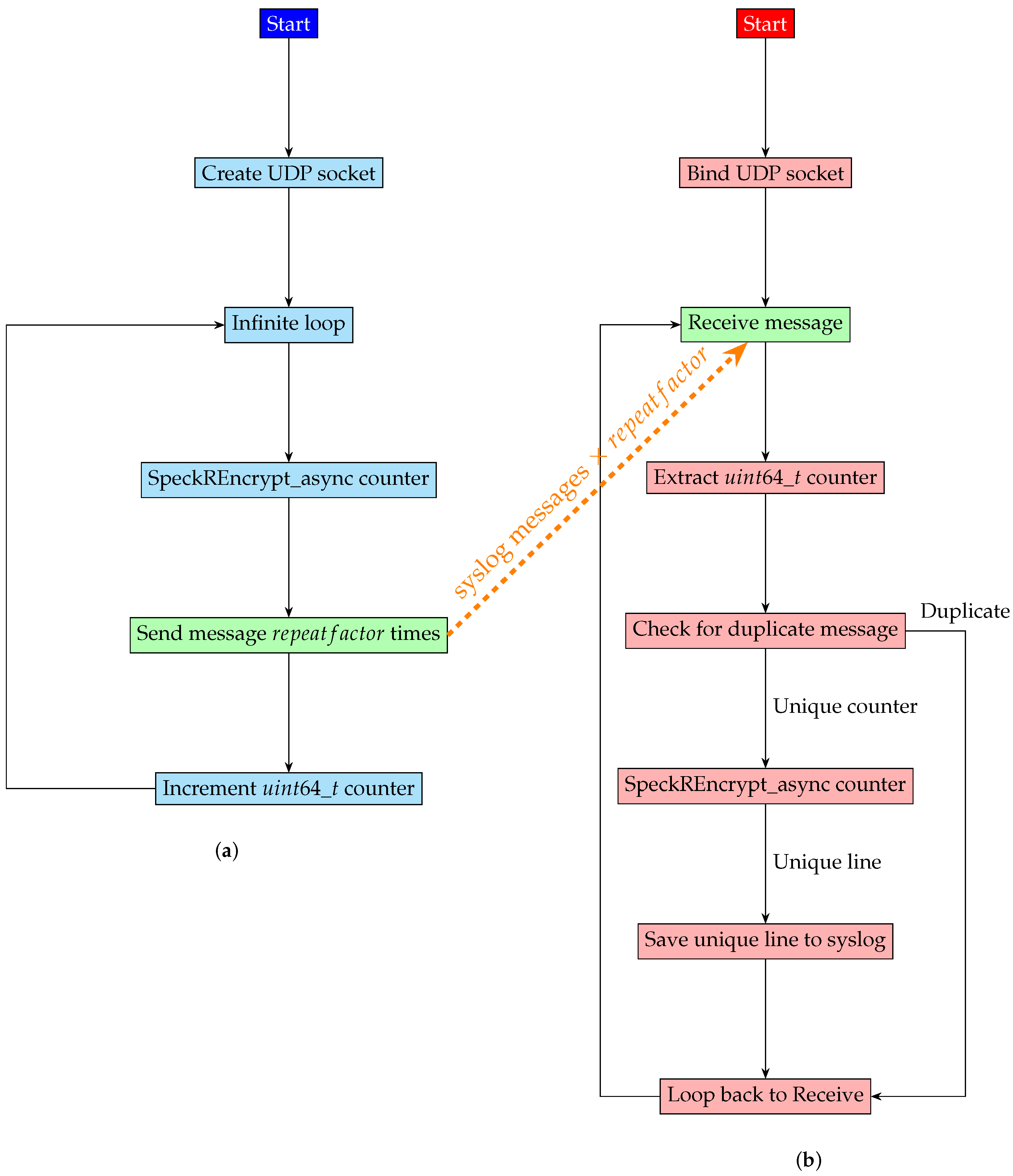
Algorithm 5 uses a constant in order to boost the sending of each message by repeating it a number of times (i.e., 100–1000). A counter is prefixed in front of each message such that the decoder can eliminate duplicates, automatically making sure that each message packet is going to be processed exactly once at the receiver side. This is of utmost importance for the decryption algorithm since internal counters in the cryptography routines in the default counter mode of operation (CTR) greatly depend on the fact that the inserted packet counters are unique.
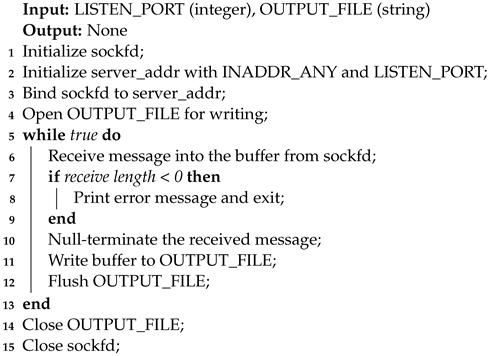
Algorithm 6 describes the receiver side, where, for the sole purpose of counting missing packets, the decrypted lines are stored in a text file. The receiver software version 1.00 available on Github [
53] relays the original syslog messages to a local syslog instance.
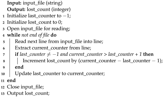
The script in Algorithm 7 is used to detect the number of missing packets, when syslog messages are sent through the data diode.
In the source code available on Github [
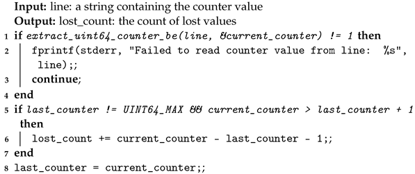
53], the message counter works as shown by Algorithm 8.
For encryption, a context variable is used to hash the encryption password using Argon2i [
54] and keep track of all counters. This is shown in Algorithm 9. This version of the Argon2 password hashing competition winner (PHC) [
55] is memory-independent, making a brute-force attack much more difficult to carry out. The encryption password has been replaced with the serial number of the data diode in [
53].
| Algorithm 5: UDP Sender Algorithm. |
![Sensors 24 06537 i005 Sensors 24 06537 i005]() |
| Algorithm 6: UDP Receiver Algorithm. |
![Sensors 24 06537 i006 Sensors 24 06537 i006]() |
| Algorithm 7: Message Counter Script Algorithm for Measurements. |
![Sensors 24 06537 i007 Sensors 24 06537 i007]() |
| Algorithm 8: Message Counter—source code algorithm. |
![Sensors 24 06537 i008 Sensors 24 06537 i008]() |
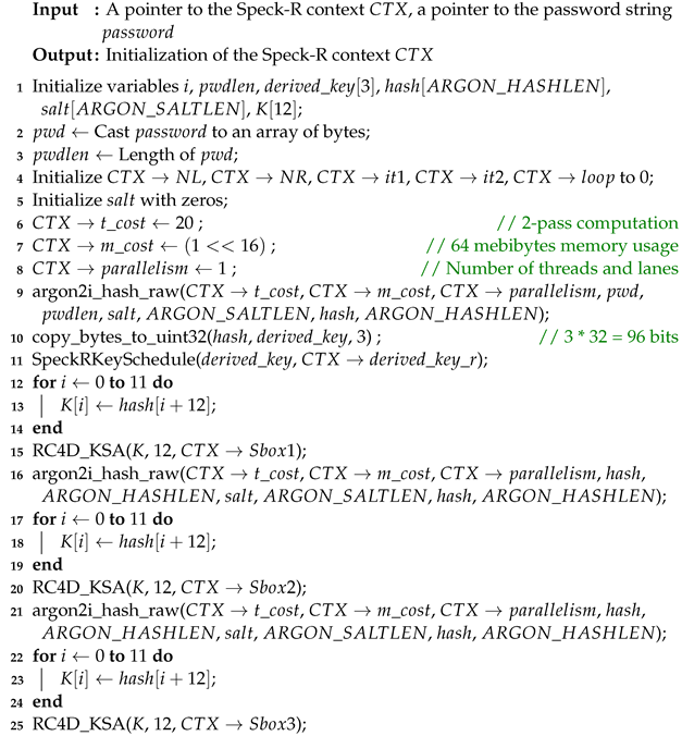
In line 10 of Algorithm 9, the resulting Argon2 hash is used to populate the 96-bit derived key with pseudo-random data obtained from the serial number of the device.
The serial number is also used to generate pseudorandom values for the key scheduling algorithm in [
41] at lines 15, 20, and 25. These lines use Algorithm 4 in order to initialize the 3 substitution boxes
,
, and
.
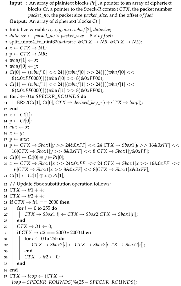
The asynchronous Speck-R encryption and decryption function developed in [
53] is shown in Algorithm 10. In the counter-mode-based block cipher, the encryption and decryption are performed by the same function. The asynchronous version of Speck-R derives this counter value in left-side (
) and right-side (
) words based on the current location of the block to be encrypted or decrypted, called
—see line 2 of Algorithm 10. This function was designed to cope with datagram packets like UDP that do not always arrive in the same order in which they were sent.
The position indicated by the variable
and the values of the counters
and
involved in updating the dynamic substitution boxes must be perfectly synchronized between the sender and the receiver of the log messages; that is, both ends of the data diode have to be perfectly synchronized, meaning that the first message sent by the sender is going to be the first message received by the log concentrator. This is important also when rebooting the device.
| Algorithm 9: Initialization of the Speck-R context (speckr_init function). |
![Sensors 24 06537 i009 Sensors 24 06537 i009]() |
The log message counter is 64 bits to avoid overflowing. The upper-bound value for this counter is greater than . The counter is not part of the real log message; it is only used for deduplication of packets. In line 3 of Algorithm 10, the context counters and are manually initialized based on the current value.
Efforts have been made to ensure that the source code in [
53] for the log amplifier and also in [
39] for the improved implementation of Speck-R are independent of endianness; that is, no matter if the sender or the receiver is compiled on hardware with incompatible endianness, the system for amplifying and deamplifying encrypted logs through the data diode still works.
Figure 9 summarizes the flow chart for the two programs: (a) the sender on the input side of the data diode and (b) the collector on the high-security network side.
The two software parts have flowcharts that are drawn side by side to make it very visible that the decryption process depends on the synchronization of the 64-bit counter on both sides. Both programs need to start the encryption of log messages using the same counter.
| Algorithm 10: SpeckREncrypt_async function. |
![Sensors 24 06537 i010 Sensors 24 06537 i010]() |
The amplifier software part listens on port 1514 on a host IP within the low-security network, and the deamplifier listens by default on port 2514 somewhere within the high-security network.
In order to enable the data diode syslog amplifier to receive messages, a client syslog concentrator from the low-security network should be configured to send data into it:
In /etc/rsyslog.conf:
. @datadiode-amplifier-host-ip:1514
On the other end of the data diode, inside the higher-security network, a local rsyslog UDP server should listen for the deamplified and decrypted messages:
In /etc/rsyslog.conf:
module(load="imudp") input(type="imudp" port="514" Address="127.0.0.1")
If this server is not the local host, the “Address” parameter must take an IP from within the internal network to make itself reachable by the receiver software part. Similar settings must be added for other flavors of the syslog service.
The next section presents the resulting measurements obtained using the software and the setups previously explained.
