Communication

Comparison Analysis of Roundness Measurement of Small Cylindrical Workpieces with Different Styluses

by
Borong Wu
1,
Chuang Zeng
2 and
Qiaolin Li
2,*
1
Chongqing University-University of Cincinnati Joint Co-op Institute, Chongqing University, Chongqing 400044, China
2
Shenzhen International Graduate School, Tsinghua University, Shenzhen 518055, China
*
Author to whom correspondence should be addressed.
Sensors 2024, 24(12), 3819; https://doi.org/10.3390/s24123819
Submission received: 14 May 2024 / Revised: 4 June 2024 / Accepted: 12 June 2024 / Published: 13 June 2024
(This article belongs to the Special Issue Applications of Manufacturing and Measurement Sensors)

Abstract

:
To investigate the high-accuracy roundness metrology of a needle roller 1.5 mm in diameter and 5.8 mm in length using the stitching linear scan method, a ruby ball stylus with a tip radius of 150 μm and a diamond stylus with a tip radius of 2 μm were employed to perform experiments under the same conditions. The precision coordinate data, derived from the needle roller’s cross-sectional circumference, were segmented into uniform eighths, each scanned with the stylus of a roughness measuring machine. The roundness profile of the needle roller was obtained by stitching the arc profiles, which were characterized according to the precision coordinate data of the arcs. The cross-correlation function, Euclidean distance, residual sum of squares, position error, and curvature of the measured arcs were used to evaluate the results, which can reflect the performance of the stylus. A comparison of the results obtained using the ruby ball stylus versus the diamond stylus demonstrates the ruby ball stylus’ greater suitability for use in the roundness metrology of the needle roller bearing examined in this paper.

1. Introduction

As fundamental components in manufacturing processes, cylindrical workpieces are pivotal in various industrial fields, including agricultural machinery, intelligent automobiles, additive manufacturing, metallurgical industries, marine vessels, and microelectronic processing [1,2,3,4,5,6]. Their multifunctionality makes them indispensable components within mechanical systems, such as gears, rotating cylinders, crankshafts, and other precision machines [7,8,9]. Among these, roundness serves as a critical quality control parameter that significantly influences the functionality, performance, and lifetime of these components [10,11,12]. An accurate roundness measurement not only validates compliance with design specifications but also has a direct impact on product performance [13]. However, current measurement techniques have limitations, particularly when it comes to accurately evaluating small workpieces. Common roundness measurement methods include the two-point method and the use of roundness gauges. These methods rely on the measurement personnel’s skill and are susceptible to errors caused by workpiece eccentricity and tilt, especially as the dimensions of the cylindrical workpiece being measured decrease, complicating the accuracy of the roundness measurement. Workpieces less than 3 mm in diameter present particular difficulties in this regard [14,15,16].
Over the years, many roundness measurement methods have been proposed. For example, Ma Yu-zhen [17] introduced a spindle roundness measurement method based on a capacitive scanning system that uses three capacitive displacement probes to eliminate spindle errors through averaging effects, thereby achieving roundness error separation and confirming the effectiveness of the measurement system. Bin Duan [18] proposed a novel roundness measurement method based on single-probe scanning that simplifies mathematical processing without requiring complex forward and backward Fourier transforms. Through simulation analysis, the method’s feasibility and repeatability were verified, and the roundness measurement’s accuracy was significantly improved. Jie Liang [19] introduced a method for measuring roundness using a laser profile scanner and merging the line point cloud data, using two-dimensional laser displacement sensors to collect line point cloud data and merging them radially and circumferentially to achieve micrometer-level high-precision measurement. Jiao Bai et al. [20] proposed a three-probe measurement method based on error separation technology. They used the Monte Carlo method to analyze the effects of sensor angle, off-axis distance, and harmonic suppression on error separation. Using a spectral confocal displacement sensor for roundness measurement, high-precision measurements in the sub-micron range were achieved. Erik Oertel [21] proposed a roundness measurement method based on an atomic force microscope, which enables the high-precision measurement of small, complex components through surface scanning and stitching algorithms. Eiki Okuyama [22] proposed a combined method, using the three-point method for roundness contour measurement and the integral method for straightness contour measurement. Through the three-point method, the roundness contour of the workpiece and the radial movement of the rotary table were separated, and reverse filtering was used to restore the original roundness contour, thus ensuring measurement stability. A Küng [23] proposed a roundness measurement method based on a three-dimensional coordinate measuring machine, reducing the motion mass and ensuring low isotropic stiffness through the innovative design of the flexible hinge–parallel motion structure, further improving the roundness measurement accuracy. These methods include the use of rotary scanning roundness testers, two-point or three-point methods, and coordinate measuring machines. Although these methods have proven effective in many cases, the influence of workpiece eccentricity on roundness measurement becomes more pronounced when measuring small cylindrical workpieces, especially when the diameter is less than 3 mm, making accurate measurement unattainable [24]. The non-contact measurement methods proposed by relevant scientists, particularly that of roundness measurement using spectral confocal technology, can eliminate the errors introduced by contact-based measurements, improving measurement accuracy [25,26,27,28]. However, accurate measurement remains a challenge, especially when dealing with small, weakly reflective objects. Therefore, research into contact-based methods remains crucial. To overcome the difficulties of measuring small-sized workpieces, relevant teams have proposed a stitching linear scan method using hardware filters [29,30,31,32,33,34]. The efficient filtering of high-frequency data and its impact mitigation have been achieved by replacing a diamond stylus with a tip radius of 2 μm with a ruby stylus with a tip radius of 150 μm. This substitution has allowed for the precise measurement of roundness in cylindrical rollers, which have dimensions of 10 mm in length and 1.5 mm in diameter. A roundness profile was reconstructed by splicing a series of circular arcs to derive roundness values, thereby facilitating the high-precision measurement of small cylindrical workpieces. This method has been shown to have exceptional measurement accuracy and repeatability for several critical measurement outcomes during the assessment of small-sized workpieces, in contrast to the conventional stitching linear scan method. Therefore, it is essential to investigate how using different-sized styluses impacts the results of workpiece roundness measurement through comparative analysis, especially for small-sized workpieces.
In this paper, experiments in roundness metrology were conducted on a small cylindrical workpiece, 1.5 mm in diameter and 5.8 mm in length, to investigate the efficacy of the stitching linear scan method for measuring roundness, with both diamond and ruby ball styluses employed, respectively. Quantitative analyses were conducted using the cross-correlation function, Euclidean distance, residual sum of squares, position error, and curvature. The measuring performance was evaluated by comparing the results obtained with the ruby ball stylus to the results obtained with the diamond stylus.

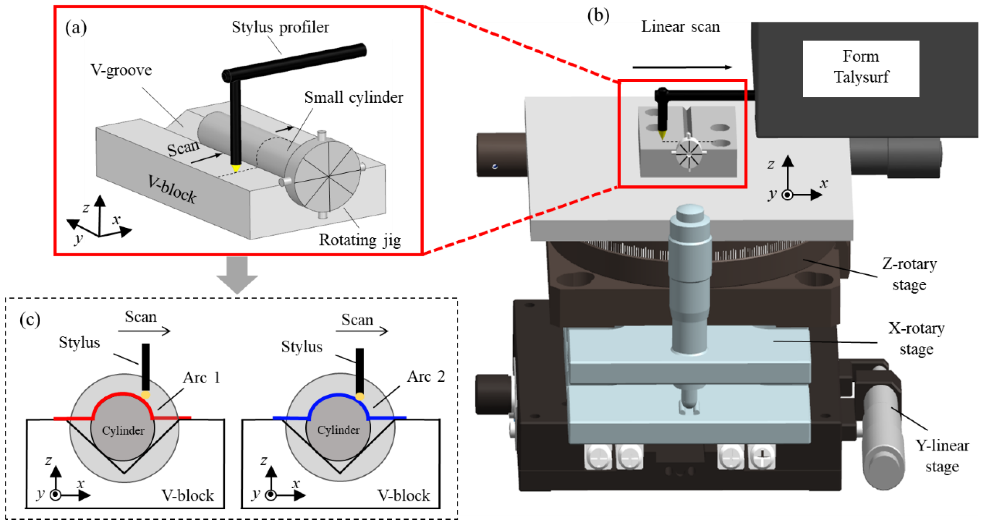
2. Principle and Experiments

The surface topography of the measured needle roller on a nano-scale can be conceptualized as a form which can be reconstructed with coordinates. Thus, a profilometer is employed to obtain these coordinates. As shown in Figure 1b, a Taylor Hobson Form Talysurf PGI 420 (VirtualExpo, Marseille, France) roughness measuring machine, with specifications shown in Table 1, is used to perform the experiments. As shown in Figure 1a, the needle roller is attached with a rotating jig and positioned on a V-block mounted on a multi-degree-of-freedom stage. Prior to conducting experiments, alignment through the adjustment of the stage’s position around the X and Z axes must be achieved. As shown in Figure 1c, the stylus of the roughness measuring machine scans across the needle roller surface and returns to the initial position. Arc coordinate data can be obtained. Subsequently, the rotating jig is manipulated to rotate 45°, causing the needle roller to also rotate by 45°, after which the stylus performs a second scan to obtain the subsequent arc coordinate data. This process is repeated until the entire cross-section circle has been scanned. As shown in Figure 2, eight arc coordinate data are obtainable. Of note, there is an overlapping portion for adjacent arc stitching.
As shown in Figure 3, two sets of experiments were conducted under identical conditions. One employed a diamond stylus with a tip radius of 2 μm, while the other used a ruby ball stylus with a tip radius of 150 μm. This enabled the characterization of arc profiles through data processing. Figure 4 and Figure 5 show the eight arc profiles characterized according to the arc coordinate data obtained using a diamond stylus and a ruby ball stylus, respectively.
The roundness profile of the needle roller is effectively reconstructed through the assembly of the eight arc profiles. Figure 6 shows the arc profile transformation, from the X-Z to the θ Δ R coordinate system, which enhances the visualized matching of adjacent arc profiles. Figure 6a,b show the matching of adjacent arc profiles from the diamond and ruby styluses, respectively. The cross-correlation function serves to evaluate the circumferential matching of the overlapping portions between adjacent arc profiles, as defined in Equation (1). In this context, C represents the coefficient, g ( θ ) denotes the plotted arc profile, and θ denotes the angular position of the arc profiles. The Euclidean distance, as defined by Equation (2), evaluates the radial matching for the overlapping portion between adjacent arc profiles, where Δ r is the difference between the radius and the reference radius in accordance with each coordinate on each arc coordinate data.
C i ~ i + 1 = g i ( θ ) g i + 1 ( θ + Δ θ i ~ i + 1 ) d θ
D i ~ i + 1 = 1 n c i , j = 1 n c ( θ i , j θ i + 1 , j ) 2 + ( Δ r i , j Δ r i + 1 , j ) 2
In general, a higher coefficient value is indicative of a superior circumferential alignment, while a smaller Euclidean distance is indicative of an improved radial alignment.
Only if both the circumferential matching and radial matching are good may the matching be considered good. The roundness profile and its corresponding value are affected by two types of roundness matching. A position error, θ E , occurs during the scanning with the diamond and ruby ball styluses, as shown in Figure 7(a1,b1). Therefore, the trajectory of the stylus on the surface of the needle roller is not always a circle but an ellipse. The position error can be calculated by Equation (3), where d m e a n is the small cylinder’s diameter and a e l l i p s e is the ellipse’s long axis.
θ E = d m e a n / a e l l i p s e
The quality of the eight arc coordinate data can be evaluated by calculating the mean curvature K , as shown in Figure 7(a2,b2). The high-frequency data that can affect the stitching of the adjacent arc profile, as well as the final roundness profile, can be calculated by the residual sum of squares between the reference radius and radius in accordance with each coordinate on each arc coordinate data, as shown in Figure 7(a3,b3).

3. Comparison Analysis

Two sets of roundness measurements were performed using a ruby ball and a diamond stylus, respectively, and the measurement performance of the two styluses was quantitatively analyzed using the evaluation methods described above. Figure 8a shows the coefficient for adjacent arc profiles, characterized by the arc coordinate data from the ruby ball stylus, which has a mean matching value of 0.845. This value is lower than the 0.798 coefficient obtained from the diamond stylus, indicating a superior circumferential alignment. Figure 8b shows that the mean Euclidean distance for the overlapping portions of adjacent arc profiles, characterized by the arc coordinate data scanned using the diamond stylus, is 26.44 nm, which is greater than the 24.59 nm with respect to the ruby ball stylus. This indicates that the stitched roundness profile obtained with the diamond stylus exhibits a greater degree of deviation compared to that obtained when using the ruby ball stylus. Figure 8c shows that the high-frequency data of the eight arc profiles with respect to the ruby ball stylus are 14.55 nm, which is less than the result of 23.40 nm with respect to the diamond stylus, indicating a smoother measured profile. As the fitting arc coordinates obtain the arc profiles, the curvature and position errors can reflect the data from the eight arc coordinates.
The accuracy of the stitching of a roundness profile can be affected by a number of factors, including the matching coefficient of adjacent arcs, the Euclidean distance of overlapping portions of arc profiles, and the high-frequency data of the profiles, with these quantitative results presented in Table 2 for comparison. Figure 9 shows the final roundness profiles for the needle roller, with dimensions 1.5 mm in diameter and 5.8 mm in length. Figure 9(a1,b1) show the stitched roundness profile, as measured by the diamond stylus. Figure 9(a2,b2) show the roundness profile following the integration of the overlapping portion of adjacent arc profiles. Figure 9(a3,b3) show the roundness profile at the 50UPR filter. Similarly, Figure 9(c1–c3,d1–d3) show the roundness profiles with respect to the ruby ball stylus. Table 3 presents the quantitative data, which show that the ruby ball stylus’s measurement data outperforms that of the diamond ball stylus.

4. Conclusions

A roughness measuring machine was employed in experiments on the roundness metrology of a needle roller measuring 1.5 mm in diameter and 5.8 mm in length, using the stitching linear scan method. The needle roller’s roundness profile was reconstructed by stitching a series of arc profiles, according to the arc coordinate data obtained using a diamond stylus with a 2 μm tip radius and a ruby ball stylus with a 150 μm tip radius. The position error of the measurement and the curvature of the obtained arc were used to evaluate the arc coordinate data quality. The mean matching coefficient of adjacent arc profiles, the mean Euclidean distance of overlapping portions of adjacent arc profiles, and the high-frequency data were calculated to evaluate the roundness profile stitching quality. The results of the evaluation show that the arc coordinate data and roundness profile, with respect to the ruby ball stylus, demonstrate greater accuracy compared to the corresponding data from the diamond stylus. This indicates that the ruby ball stylus is more effective for measuring the roundness of small-sized needle rollers. The final roundness measurements of the needle roller, as determined by the diamond stylus and the ruby ball stylus, were found to be 0.16 μm and 0.14 μm, respectively. However, as the sole focus of this experiment was on the roundness measurements of a small needle roller with a diameter less than 3 mm and a length less than 50 mm, using styluses with different tip radii, other parameters, such as the stylus material, scanning speed, workpiece radius, and scanning rate, were not examined. Consequently, the inferences derived from this study are subject to certain constraints. In the future, experiments will be conducted to explore the performance of different styluses in measuring the roundness of rollers of various sizes. Additionally, experiments will be conducted to integrate other parameters, including conducting experiments on small-sized workpieces using large-sized styluses at low sampling rates.

Author Contributions

Conceptualization, Q.L.; Software, C.Z.; Validation, B.W.; Formal analysis, B.W.; Resources, B.W.; Data curation, C.Z.; Writing—original draft, B.W.; Writing—review & editing, Q.L.; Visualization, B.W.; Supervision, Q.L.; Project administration, Q.L. All authors have read and agreed to the published version of the manuscript.

Funding

This research received no external funding.

Institutional Review Board Statement

Not applicable.

Informed Consent Statement

Informed consent was obtained from all subjects involved in the study.

Data Availability Statement

Data are contained within the article.

Conflicts of Interest

The authors declare no conflict of interest.

References

  1. Polák, P.; Mikuš, R.; Kročko, V. Monitoring of conditions of agricultural machines’ parts in operation. Res. Agric. Eng. 2014, 60, S57–S65. [Google Scholar] [CrossRef]
  2. Aliakbari, K. Failure Analysis of Ductile Iron Crankshaft in Four-Cylinder Diesel Engine. Int. J. Met. 2021, 15, 1223–1237. [Google Scholar] [CrossRef]
  3. Sanaei, N.; Fatemi, A.; Phan, N. Defect characteristics and analysis of their variability in metal L-PBF additive manufacturing. Mater. Des. 2019, 182, 108091. [Google Scholar] [CrossRef]
  4. Adamczak, S.; Zmarzły, P.; Janecki, D. Theoretical and Practical Investigations Of V-Block Waviness Measurement of Cylindrical Parts. Metrol. Meas. Syst. 2015, 22, 181–192. [Google Scholar] [CrossRef]
  5. Khaeroman, K.; Haryadi, G.D.; Ismail, R.; Kim, S.J. Failure analysis and evaluation of a six cylinders crankshaft for marine diesel generator. AIP Conf. Proc. 2017, 1788, 030064. [Google Scholar]
  6. Lee, D. Experimental Investigation of Laser Ablation Characteristics on Nickel-Coated Beryllium Copper. Metals 2018, 8, 211. [Google Scholar] [CrossRef]
  7. Bleicher, F.; Biermann, D.; Drossel, W.G.; Moehring, H.C.; Altintas, Y. Sensor and actuator integrated tooling systems. CIRP Ann. 2023, 72, 673–696. [Google Scholar] [CrossRef]
  8. Swiderski, J.; Makiela, W.; Dobrowolski, T.; Stepien, K.; Zuperl, U. The study of the roundness and cylindricity deviations of parts produced with the use of the additive manufacturing. Int. J. Adv. Manuf. Technol. 2022, 121, 7427–7437. [Google Scholar] [CrossRef]
  9. Pellegrini, G.; Ravasio, C. Study of the Law Motion of the Micro-EDM Drilling Process. J. Manuf. Mater. Process. 2023, 7, 165. [Google Scholar] [CrossRef]
  10. Liu, F.; Liang, L.; Xu, G.; Hou, C.; Liu, D. Measurement and evaluation of cylindricity deviation in Cartesian coordinates. Meas. Sci. Technol. 2020, 32, 035018. [Google Scholar] [CrossRef]
  11. Rangappa, R.; Patel, G.C.M.; Chate, G.R.; Lokare, D.; Lakshmikanthan, A.; Giasin, K.; Pimenov, D.Y. Coaxiality error analysis and optimization of cylindrical parts of CNC turning process. Int. J. Adv. Manuf. Technol. 2022, 120, 6617–6634. [Google Scholar] [CrossRef]
  12. Jiang, K.; Chen, S.; Li, Z.; Ma, T.; Ren, J.; Mao, Z. Cylindrical-cam modulation instantaneous angular speed sensor for reciprocating-rotary machine. Mech. Syst. Signal Process. 2023, 205, 110860. [Google Scholar] [CrossRef]
  13. Maropoulos, P.G.; Ceglarek, D. Design verification and validation in product lifecycle. CIRP Ann. 2010, 59, 740–759. [Google Scholar] [CrossRef]
  14. Chen, X.; Dai, Y.; Hu, H.; Tie, G.; Guan, C. Research on High Precision and Deterministic Figuring for Shaft Parts Based on Abrasive Belt Polishing. Materials 2019, 12, 1389. [Google Scholar] [CrossRef] [PubMed]
  15. Çiçek, A.; Kıvak, T.; Ekici, E. Optimization of drilling parameters using Taguchi technique and response surface methodology (RSM) in drilling of AISI 304 steel with cryogenically treated HSS drills. J. Intell. Manuf. 2013, 26, 295–305. [Google Scholar] [CrossRef]
  16. Zhu, W.-L.; Beaucamp, A. Compliant grinding and polishing: A review. Int. J. Mach. Tools Manuf. 2020, 158, 103634. [Google Scholar] [CrossRef]
  17. Ma, Y.Z.; Wang, X.H.; Li, H.M.; Dong, X.; Kang, Y.H. A New Capacitive Sensing System for Roundness Measurement. Adv. Mater. Res. 2013, 662, 754–757. [Google Scholar] [CrossRef]
  18. Duan, B.; Yin, Z.; Chai, N.; Meng, S.; Yao, J. A new single probe scanning method for on-machine measurement of roundness error. Int. J. Adv. Manuf. Technol. 2021, 116, 2861–2871. [Google Scholar] [CrossRef]
  19. Liang, J.; Sun, Z. Air conditioning compressor crankshaft roundness measurement based on a laser profiler. Meas. Sci. Technol. 2024, 35, 055010. [Google Scholar] [CrossRef]
  20. Bai, J.; Wang, Y.; Wang, X.; Zhou, Q.; Ni, K.; Li, X. Three-Probe Error Separation with Chromatic Confocal Sensors for Roundness Measurement. Nanomanuf. Metrol. 2021, 4, 247–255. [Google Scholar] [CrossRef]
  21. Oertel, E.; Manske, E. Radius and roundness measurement of micro spheres based on a set of AFM surface scans. Meas. Sci. Technol. 2021, 32, 044005. [Google Scholar] [CrossRef]
  22. Okuyama, E.; Fukuda, T. Roundness Profile Measurement Using a Combination Method of Three-Point Method for Roundness Profile Measurement and Integration Method for Straightness Profile Measurement. Int. J. Autom. Technol. 2024, 18, 77–83. [Google Scholar] [CrossRef]
  23. Küng, A.; Meli, F.; Thalmann, R. Ultraprecision micro-CMM using a low force 3D touch probe. Meas. Sci. Technol. 2007, 18, 319–327. [Google Scholar] [CrossRef]
  24. Gao, W.; Kim, S.W.; Bosse, H.; Haitjema, H.; Chen, Y.L.; Lu, X.D.; Kunzmann, H. Measurement technologies for precision positioning. CIRP Ann. 2015, 64, 773–796. [Google Scholar] [CrossRef]
  25. Bai, J.; Li, J.; Wang, X.; Zhou, Q.; Ni, K.; Li, X. A new method to measure spectral reflectance and film thickness using a modified chromatic confocal sensor. Opt. Lasers Eng. 2022, 154, 107019. [Google Scholar] [CrossRef]
  26. Bai, J.; Li, X.; Wang, X.; Wang, J.; Ni, K.; Zhou, Q. Self-reference dispersion correction for chromatic confocal displacement measurement. Opt. Lasers Eng. 2021, 140, 106540. [Google Scholar] [CrossRef]
  27. Bai, J.; Li, X.; Wang, X.; Zhou, Q.; Ni, K. Chromatic Confocal Displacement Sensor with Optimized Dispersion Probe and Modified Centroid Peak Extraction Algorithm. Sensors 2019, 19, 3592. [Google Scholar] [CrossRef] [PubMed]
  28. Bai, J.; Li, X.; Zhou, Q.; Ni, K.; Wang, X. Improved chromatic confocal displacement-sensor based on a spatial-bandpass-filter and an X-shaped fiber-coupler. Opt. Express 2019, 27, 10961–10973. [Google Scholar] [CrossRef] [PubMed]
  29. Li, Q.; Shimizu, Y.; Saito, T.; Matsukuma, H.; Cai, Y.; Gao, W. Improvement of a Stitching Operation in the Stitching Linear-Scan Method for Measurement of Cylinders in a Small Dimension. Appl. Sci. 2021, 11, 4705. [Google Scholar] [CrossRef]
  30. Li, Q.; Shimizu, Y.; Saito, T.; Matsukuma, H.; Gao, W. Measurement Uncertainty Analysis of a Stitching Linear-Scan Method for the Evaluation of Roundness of Small Cylinders. Appl. Sci. 2020, 10, 4750. [Google Scholar] [CrossRef]
  31. Li, Q.; Shimizu, Y.; Wang, X.; Li, X.; Gao, W. High-accuracy roundness measurement of small cylindrical workpieces by a high-frequency filtering method. Precis. Eng. 2024, 85, 241–246. [Google Scholar] [CrossRef]
  32. Li, Q.; Wang, Y.; Li, J.; Wang, X.; Li, X. Non-contact ultra-precision metrology of superfine cylinders with a developed two-dimensional coordinate measuring device. Measurement 2023, 223, 113727. [Google Scholar] [CrossRef]
  33. Gao, W.; Haitjema, H.; Fang, F.Z.; Leach, R.K.; Cheung, C.F.; Savio, E.; Linares, J.M. On-machine and in-process surface metrology for precision manufacturing. CIRP Ann. 2019, 68, 843–866. [Google Scholar] [CrossRef]
  34. Gao, W.; Kiyono, S.; Sugawara, T. High-accuracy roundness measurement by a new error separation method. Precis. Eng. 1997, 21, 123–133. [Google Scholar] [CrossRef]
Figure 1. The linear scan on the surface of the needle roller by a profilometer: (a) The stylus scans across the surface of the needle roller; (b) the schematic of linear scan by a profilometer; (c) the arc coordinate data obtained by the stylus scanning.
Sensors 24 03819 g001
Figure 2. The eight arc coordinate data obtained by the linear scan of the profilometer.
Sensors 24 03819 g002
Figure 3. The scheme of linear scanning with different ball sizes.
Sensors 24 03819 g003
Figure 4. The eight arc profiles characterized according to the arc coordinate data obtained using the diamond stylus.
Sensors 24 03819 g004
Figure 5. The eight arc profiles characterized according to the arc coordinate data obtained using the ruby ball stylus.
Sensors 24 03819 g005
Figure 6. The matching of adjacent arc profiles: (a) the matching of adjacent arc profiles from diamond stylus; (b) the matching of adjacent arc profiles from ruby ball stylus.
Sensors 24 03819 g006
Figure 7. The evaluation of arc coordinate data quality: (a1,b1) the position error when scanning; (a2,b2) the curvature of the arc obtained; (a3,b3) the high-frequency data of the arc obtained.
Sensors 24 03819 g007
Figure 8. The evaluation results of the diamond stylus and ruby ball stylus: (a) the histogram of matching coefficient; (b) the Euclidean distance; (c) the high frequency data.
Sensors 24 03819 g008
Figure 9. Results comparison: (a1a3,b1b3) results from two experiments using the diamond stylus; (c1c3,d1d3) results from two experiments using the ruby ball stylus.
Sensors 24 03819 g009
Table 1. The specification of Form Talysurf PGI 420.
ItemResolution (Z)Measuring Range (Z)Measuring Range (X)Sampling Step (X)Scanning Speed
Value3.241200.1250.1
Unitnmmmmmμmmm/s
Table 2. The evaluation results.
Matching
Coefficient
Euclidean
Distance
High-Frequency
Data
Position
Error
Mean
Curvature
Diamond stylus0.7826.44 nm23.40 nm3.5°1.335
Ruby ball stylus0.8524.48 nm14.55 nm2.3°1.334
Table 3. The final diameter and roundness results.
Tip RadiusDiameter of Needle RollerRoundness of Needle Roller
Diamond stylus2 μm1.497 mm0.16 μm
Ruby ball stylus150 μm1.499 mm0.14 μm
Disclaimer/Publisher’s Note: The statements, opinions and data contained in all publications are solely those of the individual author(s) and contributor(s) and not of MDPI and/or the editor(s). MDPI and/or the editor(s) disclaim responsibility for any injury to people or property resulting from any ideas, methods, instructions or products referred to in the content.

