

Inpainting Saturation Artifact in Anterior Segment Optical Coherence Tomography
Abstract
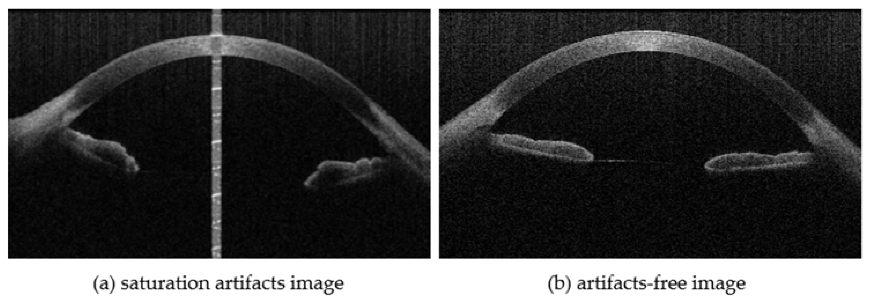
:1. Introduction
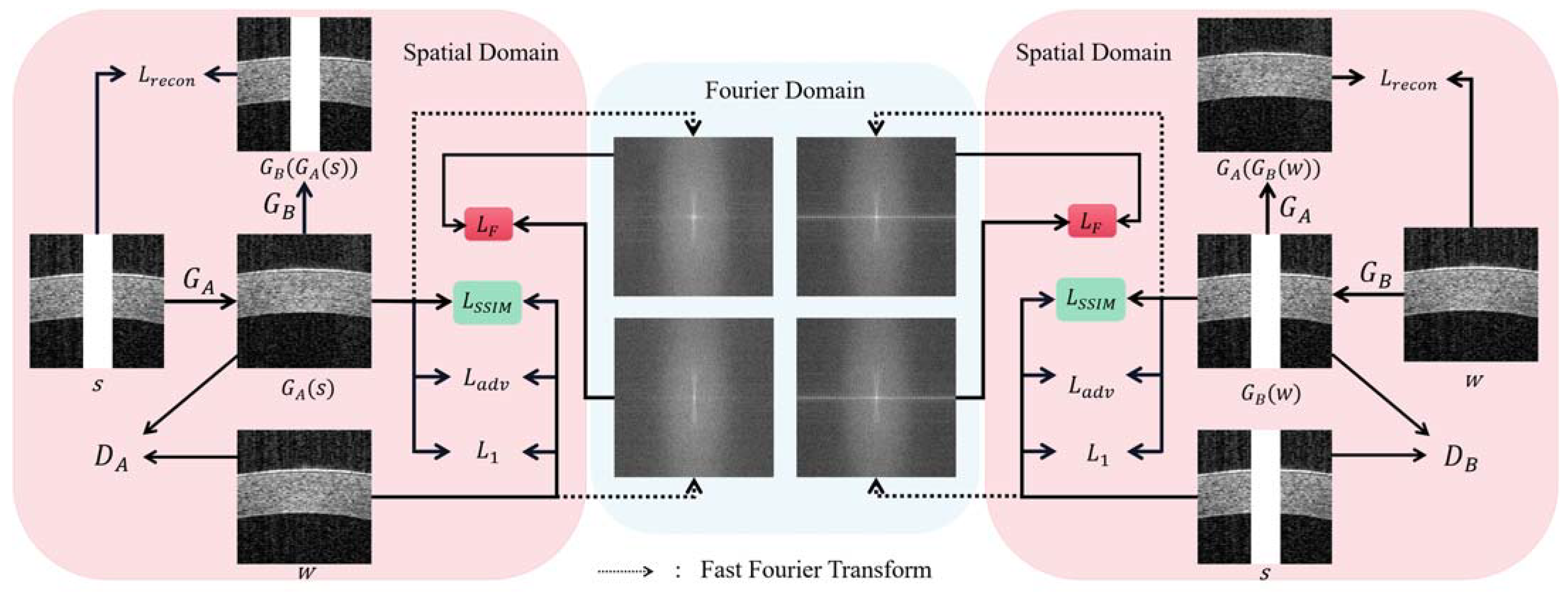
- The dual-domain transformation capability of DualGAN [21] is designed to achieve AS-OCT saturation artifact inpainting by converting the artifact image into an artifact-free image. The structural similarity loss for reconstructing the structure and texture of the cornea is incorporated;
- A frequency loss that combines the spatial and frequency domains is introduced to ensure the overall consistency of the images in both domains;
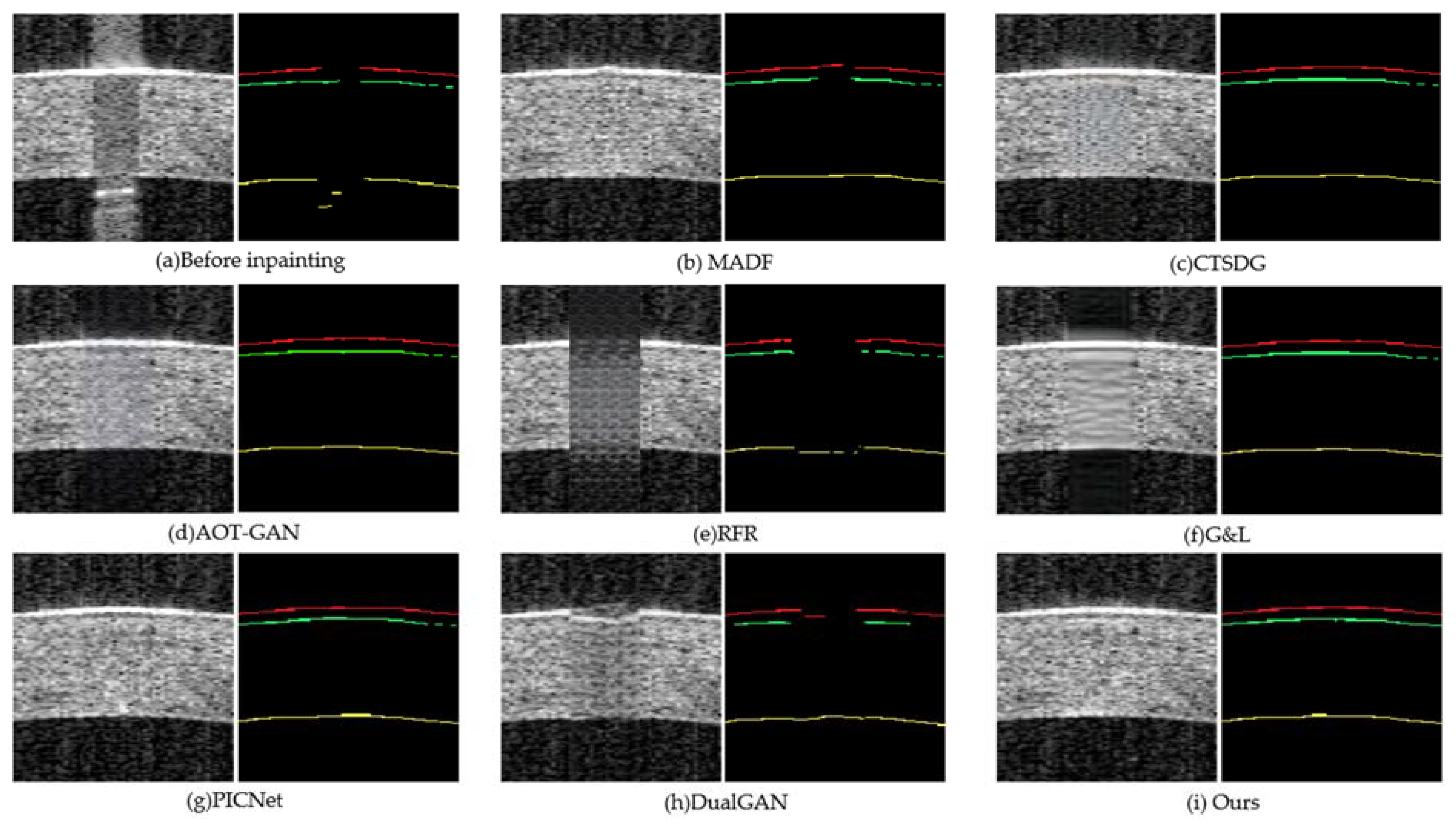
- The repair experiments on both synthetic and real artifacts are devised. The results indicate that the proposed methods can restore artifacts in different situations. To confirm the clinical value of saturation artifact inpainting, segmentation experiments are designed on the three corneal boundaries of real artifact-inpainted images, including the anterior surface of the epithelium (EP), the posterior surface of Bowman’s layer (BL), and the posterior surface of the endothelium (EN). The experimental results demonstrate that the method significantly enhances the precision of corneal segmentation, proving to be more accurate than other repair techniques.
2. Proposed Method
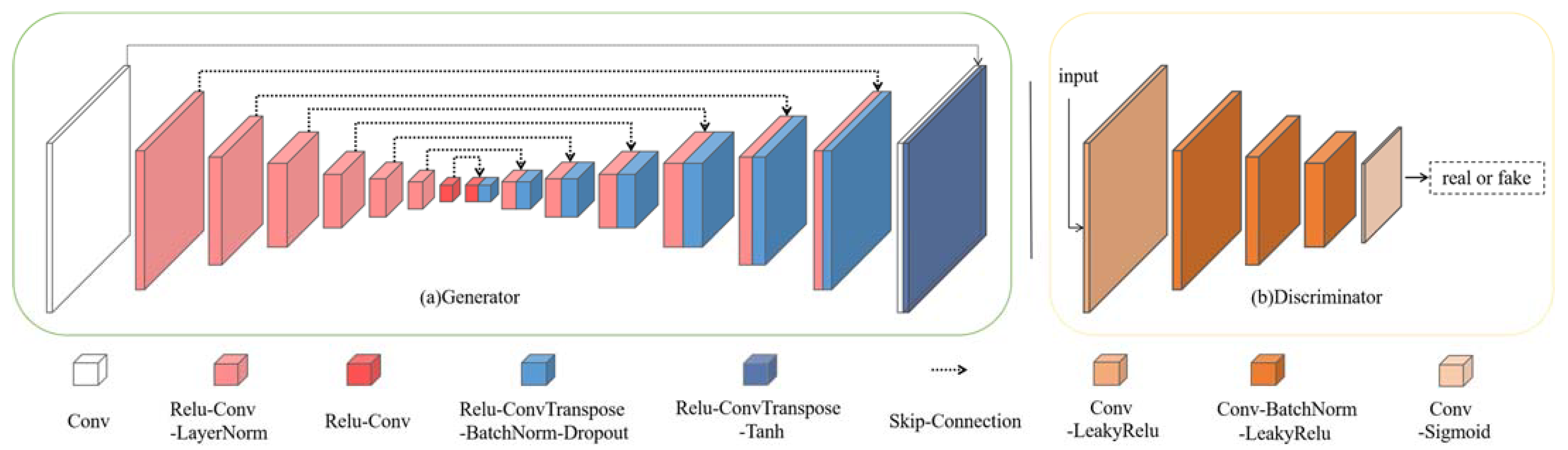
2.1. Network Architecture
2.2. Objective Functions
3. Experimental Setup and Results
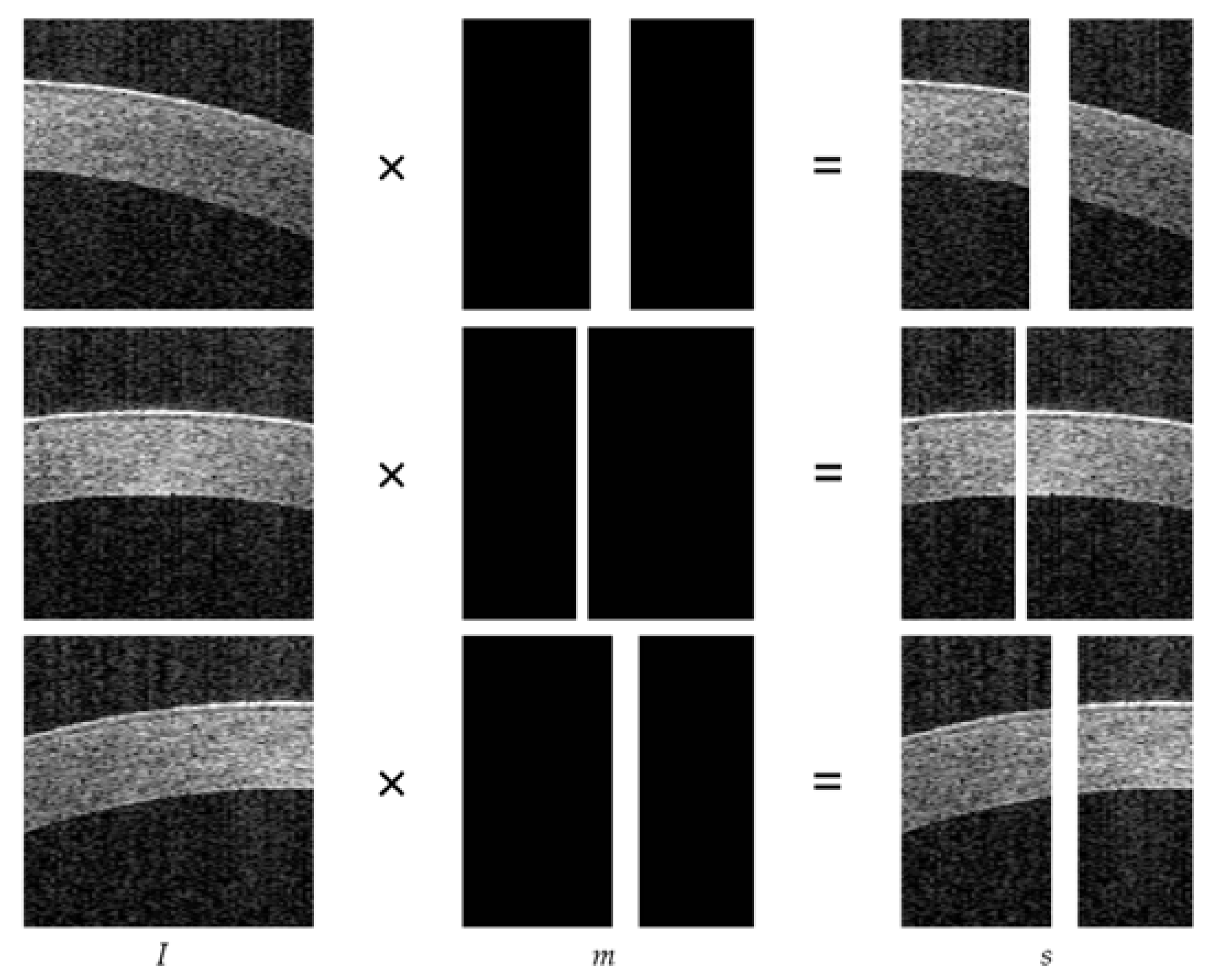
3.1. Data Preprocessing
3.2. Training Parameters
3.3. Evaluation of Inpainting
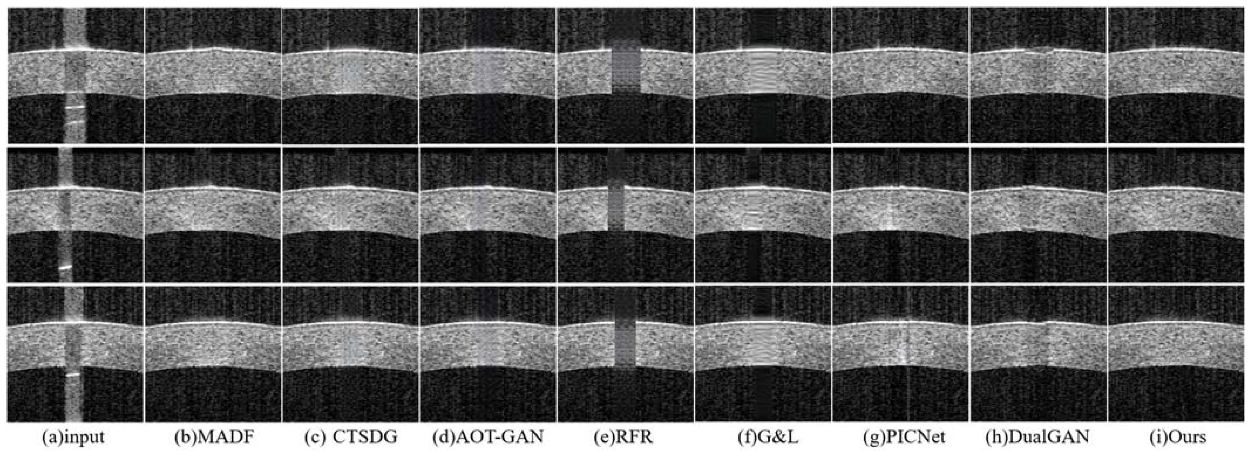
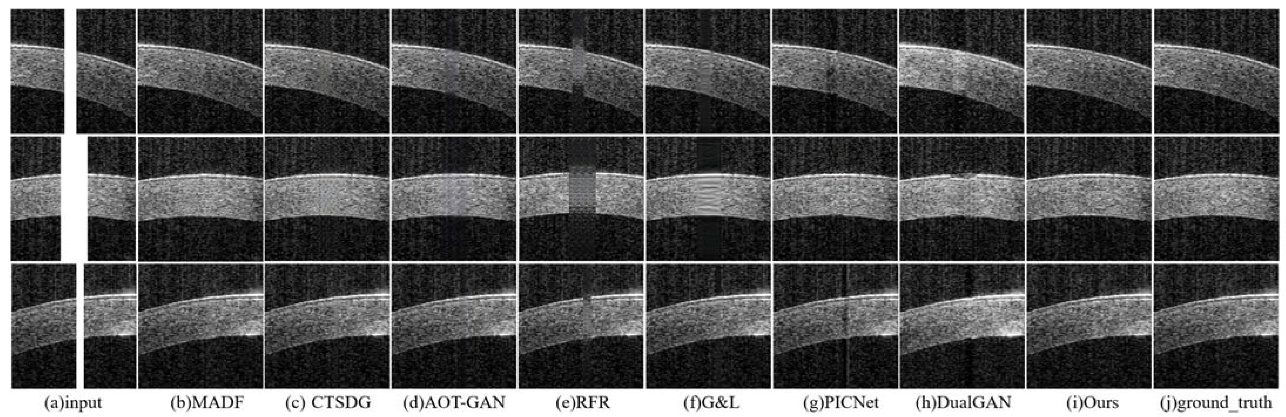
- The repair effects of different methods on corneal tissue images with different tilt degrees under the same mask conditions are shown in Figure 7;
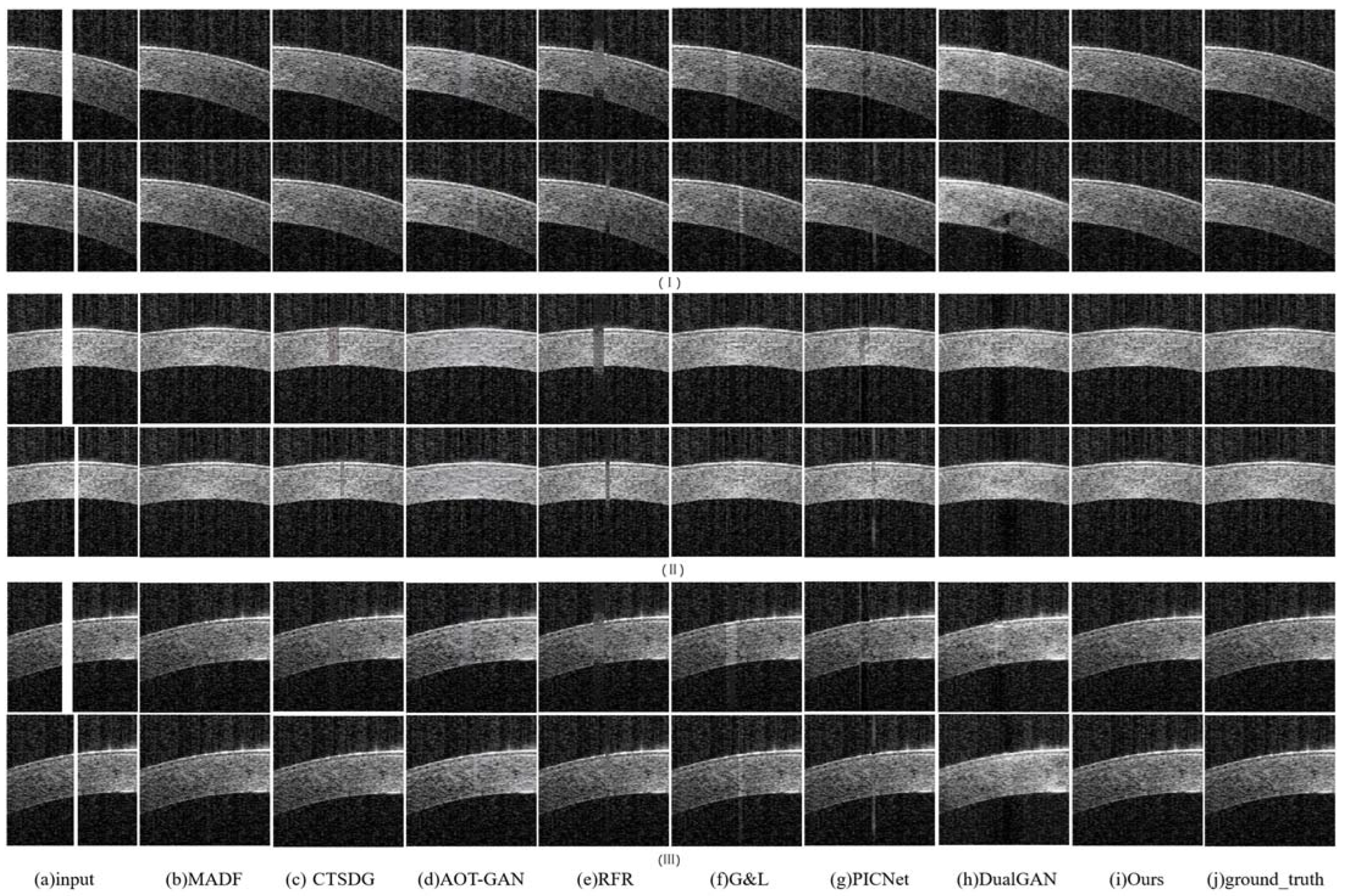
- The inpainting results of different methods on corneal tissue images with the same inclination combined with different masks are shown in Figure 8. Briefly, Figure 8 shows the image restoration effects of three groups, adding different masks to the same AS-OCT image. Figure 8(I), (II), and (III) respectively show the repair results of images with downward tilt of corneal tissue, images with no tilt degree of corneal tissue, and images with upward tilt of corneal tissue with different masks added.
- The results of adding different masks into the corneal tissue images with different degrees of inclination using different methods are shown in Figure 9.
3.4. Evaluation on Segmentation
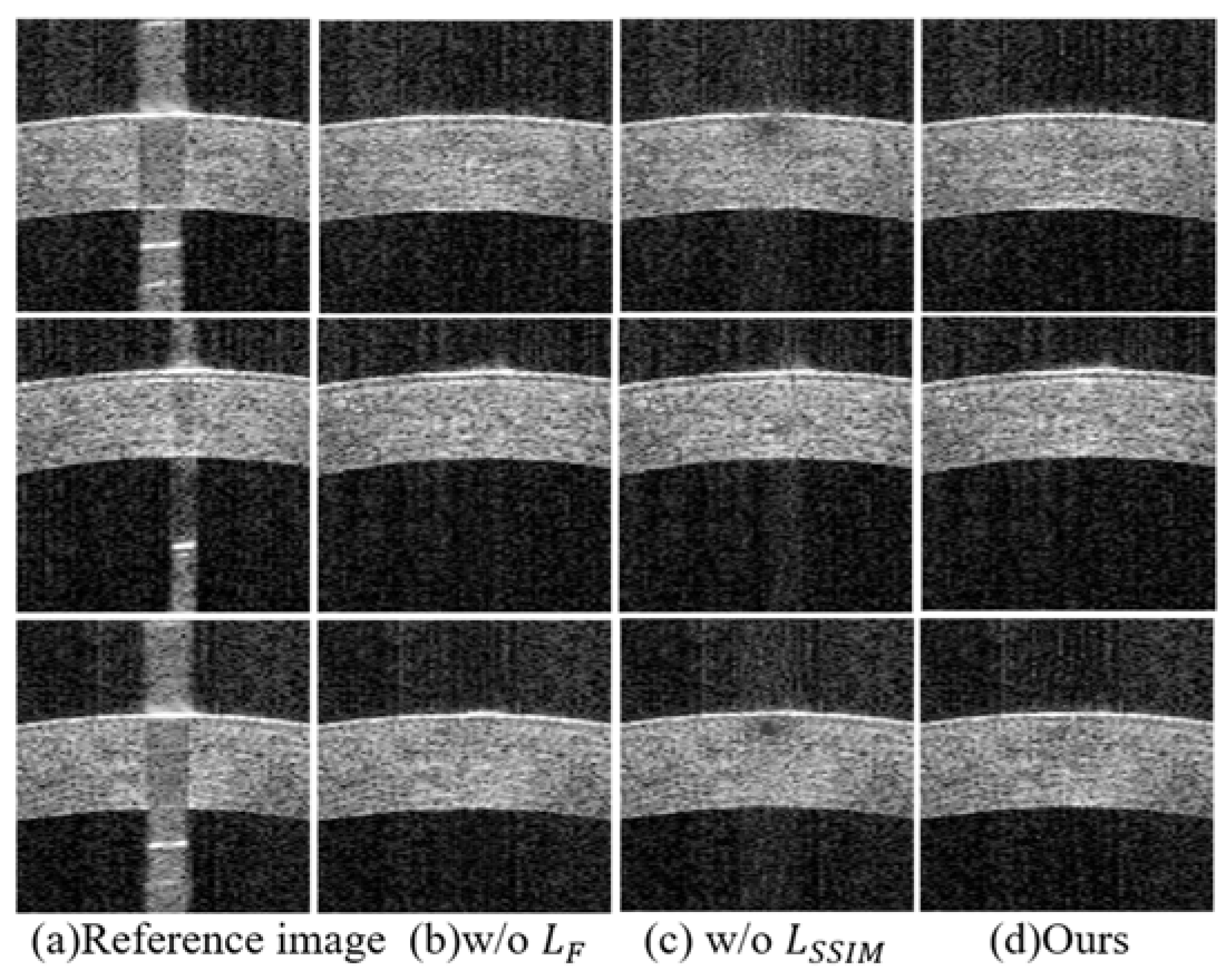
3.5. Ablation Studies
4. Conclusions
Author Contributions
Funding
Institutional Review Board Statement
Informed Consent Statement
Data Availability Statement
Conflicts of Interest
References
- Li, Y.; Shekhar, R.; Huang, D. Segmentation of 830-and 1310-nm LASIK corneal optical coherence tomography images. In Proceedings of the Medical Imaging 2002, Image Processing, SPIE, San Diego, CA, USA, 23–28 February 2002; Volume 4684, pp. 167–178. [Google Scholar] [CrossRef]
- Elsawy, A.; Gregori, G.; Eleiwa, T.; Abdel-Mottaleb, M.; Shousha, M.A. Pathological-Corneas Layer Segmentation and Thickness Measurement in OCT Images. Transl. Vis. Sci. Technol. 2020, 9, 24. [Google Scholar] [CrossRef] [PubMed]
- dos Santos, V.A.; Schmetterer, L.; Stegmann, H.; Pfister, M.; Messner, A.; Schmidinger, G.; Garhofer, G.; Werkmeister, R.M. CorneaNet: Fast segmentation of cornea OCT scans of healthy and keratoconic eyes using deep learning. Biomed. Opt. Express 2019, 10, 622–641. [Google Scholar] [CrossRef] [PubMed]
- Vincent, S.J.; Alonso-Caneiro, D.; Collins, M.J. Optical coherence tomography and scleral contact lenses: Clinical and research applications. Clin. Exp. Optom. 2018, 102, 224–241. [Google Scholar] [CrossRef] [PubMed]
- Ang, M.; Baskaran, M.; Werkmeister, R.M.; Chua, J.; Schmidl, D.; dos Santos, V.A.; Garhöfer, G.; Mehta, J.S.; Schmetterer, L. Anterior segment optical coherence tomography. Prog. Retin. Eye Res. 2018, 66, 132–156. [Google Scholar] [CrossRef] [PubMed]
- Ouyang, J.; Mathai, T.S.; Lathrop, K.; Galeotti, J. Accurate tissue interface segmentation via adversarial pre-segmentation of anterior segment OCT images. Biomed. Opt. Express 2019, 10, 5291–5324. [Google Scholar] [CrossRef]
- Yang, Y.; Gao, D.; Xie, X.; Qin, J.; Li, J.; Lin, H.; Yan, D.; Deng, K. DeepIDC: A Prediction Framework of Injectable Drug Combination Based on Heterogeneous Information and Deep Learning. Clin. Pharmacokinet. 2022, 61, 1749–1759. [Google Scholar] [CrossRef] [PubMed]
- Khan, Y.D.; Mahmood, M.K.; Ahmad, D.; Al-Zidi, N.M. Content-Based Image Retrieval Using Gamma Distribution and Mixture Model. J. Funct. Spaces 2022, 2022, 1–10. [Google Scholar] [CrossRef]
- Zhu, M.; He, D.; Li, X.; Li, C.; Li, F.; Liu, X.; Ding, E.; Zhang, Z. Image Inpainting by End-to-End Cascaded Refinement with Mask Awareness. IEEE Trans. Image Process. 2021, 30, 4855–4866. [Google Scholar] [CrossRef] [PubMed]
- Guo, X.; Yang, H.; Huang, D. Image inpainting via conditional texture and structure dual generation. In Proceedings of the IEEE/CVF International Conference on Computer Vision, Montreal, QC, Canada, 10–17 October 2021; pp. 14134–14143. [Google Scholar] [CrossRef]
- Zeng, Y.; Fu, J.; Chao, H.; Guo, B. Aggregated Contextual Transformations for High-Resolution Image Inpainting. IEEE Trans. Vis. Comput. Graph. 2022, 29, 3266–3280. [Google Scholar] [CrossRef]
- Li, J.; Wang, N.; Zhang, L.; Du, B.; Tao, D. Recurrent feature reasoning for image inpainting. In Proceedings of the IEEE/CVF Conference on Computer Vision and Pattern Recognition, Seattle, WA, USA, 14–19 June 2020; pp. 7760–7768. [Google Scholar] [CrossRef]
- Uddin, S.M.N.; Jung, Y.J. Global and Local Attention-Based Free-Form Image Inpainting. Sensors 2020, 20, 3204. [Google Scholar] [CrossRef] [PubMed]
- Zheng, C.; Cham, T.J.; Cai, J. Pluralistic image completion. In Proceedings of the IEEE/CVF Conference on Computer Vision and Pattern Recognition, Long Beach, CA, USA, 15–20 June 2019; pp. 1438–1447. [Google Scholar] [CrossRef]
- Zhang, H.; Yang, J.; Zhou, K.; Li, F.; Hu, Y.; Gao, S.; Zhang, X.; Liu, J. Eliminating Shadow Artifacts via Generative Inpainting Networks to Quantify Vascular Changes of the Choroid. arXiv 2019, arXiv:1907.01271. [Google Scholar]
- Cheong, H.; Devalla, S.K.; Pham, T.H.; Zhang, L.; Tun, T.A.; Wang, X.; Perera, S.; Schmetterer, L.; Aung, T.; Boote, C.; et al. DeshadowGAN: A Deep Learning Approach to Remove Shadows from Optical Coherence Tomography Images. Transl. Vis. Sci. Technol. 2020, 9, 23. [Google Scholar] [CrossRef]
- Liu, H.; Cao, S.; Ling, Y.; Gan, Y. Inpainting for Saturation Artifacts in Optical Coherence Tomography Using Dictionary-Based Sparse Representation. IEEE Photon J. 2021, 13, 1–10. [Google Scholar] [CrossRef] [PubMed]
- Tang, Y.; Li, Y.; Liu, H.; Li, J.; Jin, P.; Gan, Y.; Ling, Y.; Su, Y. Multi-scale sparse representation-based shadow inpainting for retinal OCT images. In Proceedings of the Medical Imaging 2022, Image Processing, SPIE, San Diego, CA, USA, 23–28 February 2002; Volume 12032, pp. 9–17. [Google Scholar] [CrossRef]
- Isola, P.; Zhu, J.-Y.; Zhou, T.; Efros, A.A. Image-to-image translation with conditional adversarial networks. In Proceedings of the IEEE Conference on Computer Vision and Pattern Recognition, Honolulu, HI, USA, 21–26 July 2017; pp. 1125–1134. [Google Scholar] [CrossRef]
- Bai, G.; Li, S.; Zhang, H.; Higashita, R.; Liu, J.; Zhang, M. A Structure-Consistency GAN for Unpaired AS-OCT Image Inpainting. In International Workshop on Ophthalmic Medical Image Analysis; Springer: Berlin/Heidelberg, Germany, 2023; pp. 142–151. [Google Scholar] [CrossRef]
- Yi, Z.; Zhang, H.; Tan, P.; Gong, M. Dualgan: Unsupervised dual learning for image-to-image translation. In Proceedings of the IEEE International Conference on Computer Vision, Venice, Italy, 22–29 October 2017; pp. 2849–2857. [Google Scholar] [CrossRef]
- Ronneberger, O.; Fischer, P.; Brox, T. U-net: Convolutional networks for biomedical image segmentation. In International Conference on Medical Image Computing and Computer-Assisted Intervention, Proceedings of International Conference on Medical Image Computing and Computer-Assisted Intervention, Munich, Germany, 5–9 October 2015; Springer: Berlin/Heidelberg, Germany, 2015; pp. 234–241. [Google Scholar] [CrossRef]
- Li, C.; Wand, M. Precomputed real-time texture synthesis with markovian generative adversarial networks. In Computer Vision, Proceedings of the ECCV 2016: 14th European Conference, Amsterdam, The Netherlands, 11–14 October 2016; Springer: Berlin/Heidelberg, Germany, 2016; pp. 702–716. [Google Scholar] [CrossRef]
- Wang, Z.; Bovik, A.C.; Sheikh, H.R.; Simoncelli, E.P. Image quality assessment: From error visibility to structural similarity. IEEE Trans. Image Process. 2004, 13, 600–612. [Google Scholar] [CrossRef] [PubMed]
- Zhao, H.; Gallo, O.; Frosio, I.; Kautz, J. Loss Functions for Image Restoration With Neural Networks. IEEE Trans. Comput. Imaging 2017, 3, 47–57. [Google Scholar] [CrossRef]
- He, H.; Yang, D.; Wang, S.; Wang, S.; Li, Y. Road Extraction by Using Atrous Spatial Pyramid Pooling Integrated Encoder-Decoder Network and Structural Similarity Loss. Remote. Sens. 2019, 11, 1015. [Google Scholar] [CrossRef]
- Yang, H.H.; Yang, C.H.H.; Tsai, Y.C.J. Y-net: Multi-scale feature aggregation network with wavelet structure similarity loss function for single image dehazing. In Proceedings of the ICASSP 2020—2020 IEEE International Conference on Acoustics, Speech and Signal Processing (ICASSP), Barcelona, Spain, 4–8 May 2020; pp. 2628–2632. [Google Scholar] [CrossRef]
- Jiang, L.; Dai, B.; Wu, W.; Loy, C.C. Focal frequency loss for image reconstruction and synthesis. In Proceedings of the IEEE/CVF International Conference on Computer Vision, Montreal, QC, Canada, 10–17 October 2021; pp. 13919–13929. [Google Scholar] [CrossRef]
- Fuoli, D.; Van Gool, L.; Timofte, R. Fourier space losses for efficient perceptual image super-resolution. In Proceedings of the IEEE/CVF International Conference on Computer Vision, Montreal, QC, Canada, 10–17 October 2021; pp. 2360–2369. [Google Scholar] [CrossRef]
- Larsen, A.B.L.; Sønderby, S.K.; Larochelle, H.; Winther, O. Autoencoding beyond pixels using a learned similarity metric. In Proceedings of the 33rd International Conference on Machine Learning, New York, NY, USA, 19–24 June 2016; Available online: http://proceedings.mlr.press/v48/larsen16 (accessed on 22 November 2023).
- Han, S.W.; Suh, D.Y. PIINET: A 360-degree panoramic image inpainting network using a cube map. Comput. Mater. Contin. 2021, 66, 213–228. [Google Scholar] [CrossRef]
- Feldman, R.M.; Kim, G.; Chuang, A.Z.; Shiraishi, A.; Okamoto, K.; Tsukamoto, M. Comparison between the CASIA SS-1000 and Pentacam in measuring corneal curvatures and corneal thickness maps. BMC Ophthalmol. 2023, 23, 10. [Google Scholar] [CrossRef] [PubMed]
- Zhang, R.; Isola, P.; Efros, A.A.; Shechtman, E.; Wang, O. The unreasonable effectiveness of deep features as a perceptual metric. In Proceedings of the IEEE Conference on Computer Vision and Pattern Recognition, Salt Lake City, UT, USA, 18–23 June 2018; pp. 586–595. [Google Scholar] [CrossRef]
- Garcia-Marin, Y.F.; Alonso-Caneiro, D.; Fisher, D.; Vincent, S.J.; Collins, M.J. Patch-based CNN for corneal segmentation of AS-OCT images: Effect of the number of classes and image quality upon performance. Comput. Biol. Med. 2023, 152, 106342. [Google Scholar] [CrossRef] [PubMed]


| Method | PSNR↑ | SSIM↑ | LPIPS↓ |
|---|---|---|---|
| Before Inpainting | 4.899 | 0.314 | 0.687 |
| MADF | 20.533 | 0.392 | 0.091 |
| CTSDG | 22.886 | 0.554 | 0.080 |
| AOT-GAN | 22.168 | 0.518 | 0.125 |
| RFR | 16.168 | 0.431 | 0.213 |
| G&L | 22.879 | 0.561 | 0.225 |
| PICNet | 19.977 | 0.461 | 0.125 |
| DualGAN | 17.9154 | 0.250 | 0.106 |
| Ours | 21.333 | 0.496 | 0.072 |
| Method | DSC↑ | PA↑ | F1-Score↑ | Jaccard↑ |
|---|---|---|---|---|
| Before Inpainting | 0.431 | 0.986 | 0.984 | 0.299 |
| MADF | 0.494 | 0.987 | 0.985 | 0.357 |
| CTSDG | 0.536 | 0.988 | 0.986 | 0.390 |
| AOT-GAN | 0.520 | 0.987 | 0.985 | 0.381 |
| RFR | 0.409 | 0.986 | 0.985 | 0.280 |
| G&L | 0.531 | 0.988 | 0.986 | 0.387 |
| PICNet | 0.482 | 0.987 | 0.985 | 0.340 |
| DualGAN | 0.470 | 0.987 | 0.985 | 0.335 |
| Ours | 0.585 | 0.989 | 0.987 | 0.444 |
| Method | DSC↑ | PA↑ | F1-Score↑ | Jaccard↑ |
|---|---|---|---|---|
| w/o | 0.570 | 0.989 | 0.987 | 0.425 |
| w/o | 0.479 | 0.987 | 0.985 | 0.338 |
| Ours | 0.585 | 0.989 | 0.987 | 0.444 |
Disclaimer/Publisher’s Note: The statements, opinions and data contained in all publications are solely those of the individual author(s) and contributor(s) and not of MDPI and/or the editor(s). MDPI and/or the editor(s) disclaim responsibility for any injury to people or property resulting from any ideas, methods, instructions or products referred to in the content. |
© 2023 by the authors. Licensee MDPI, Basel, Switzerland. This article is an open access article distributed under the terms and conditions of the Creative Commons Attribution (CC BY) license (https://creativecommons.org/licenses/by/4.0/).
Share and Cite
Li, J.; Zhang, H.; Wang, X.; Wang, H.; Hao, J.; Bai, G. Inpainting Saturation Artifact in Anterior Segment Optical Coherence Tomography. Sensors 2023, 23, 9439. https://doi.org/10.3390/s23239439
Li J, Zhang H, Wang X, Wang H, Hao J, Bai G. Inpainting Saturation Artifact in Anterior Segment Optical Coherence Tomography. Sensors. 2023; 23(23):9439. https://doi.org/10.3390/s23239439
Chicago/Turabian StyleLi, Jie, He Zhang, Xiaoli Wang, Haoming Wang, Jingzi Hao, and Guanhua Bai. 2023. "Inpainting Saturation Artifact in Anterior Segment Optical Coherence Tomography" Sensors 23, no. 23: 9439. https://doi.org/10.3390/s23239439
APA StyleLi, J., Zhang, H., Wang, X., Wang, H., Hao, J., & Bai, G. (2023). Inpainting Saturation Artifact in Anterior Segment Optical Coherence Tomography. Sensors, 23(23), 9439. https://doi.org/10.3390/s23239439