
An Integrated Approach for Real-Time Monitoring of Knee Dynamics with IMUs and Multichannel EMG


Abstract
:1. Introduction
2. Materials and Methods
2.1. Subjects
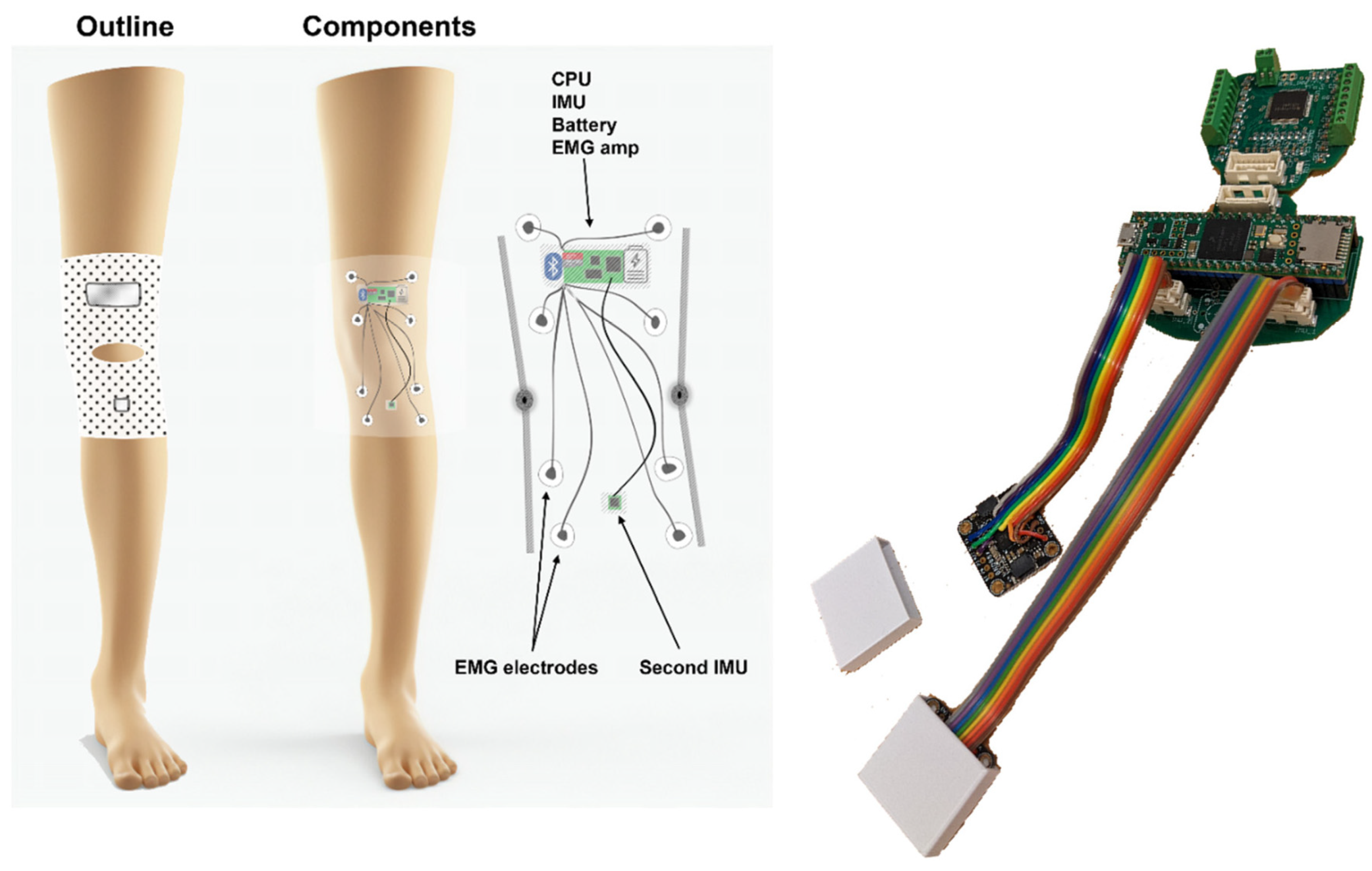
2.2. Knee Angle Measurement (KAM) Device
- Small footprint—using only essential electronic components and keeping the size of printed circuit boards minimal to enable integration into a garment and comfortable use over prolonged periods of time.
- Robust and reliable knee angle measurement—compared with mechanical angle sensors that obstruct natural ROM and/or deteriorate over time due to the mechanical strain, wear and tear, and misalignment with the axis of knee rotation, the knee angle measurement using IMU is based on two miniature integrated circuits which only have to be placed on two leg segments (thigh and shank).
- Muscle activity measurement—to complement the information related to the knee angle, the device integrates an EMG amplifier/digitizer capable of acquiring information related to muscle activity.
- Embedded microcontroller—to handle communication with IMU and EMG sensors, running knee angle calculations in real-time, and storing the data, the device has an ARM M7 microcontroller.
- 24 h measurement sessions—as one of the goals of the study is to provide whole-day knee activity measurement, the battery of the device was chosen to enable continuous power for 24 h. As in the current hardware design, it would require a relatively large discrete battery cell, to reduce the weight of the garment, the device relies on the external battery pack of 5000 mAh that is carried in the trousers pocket.
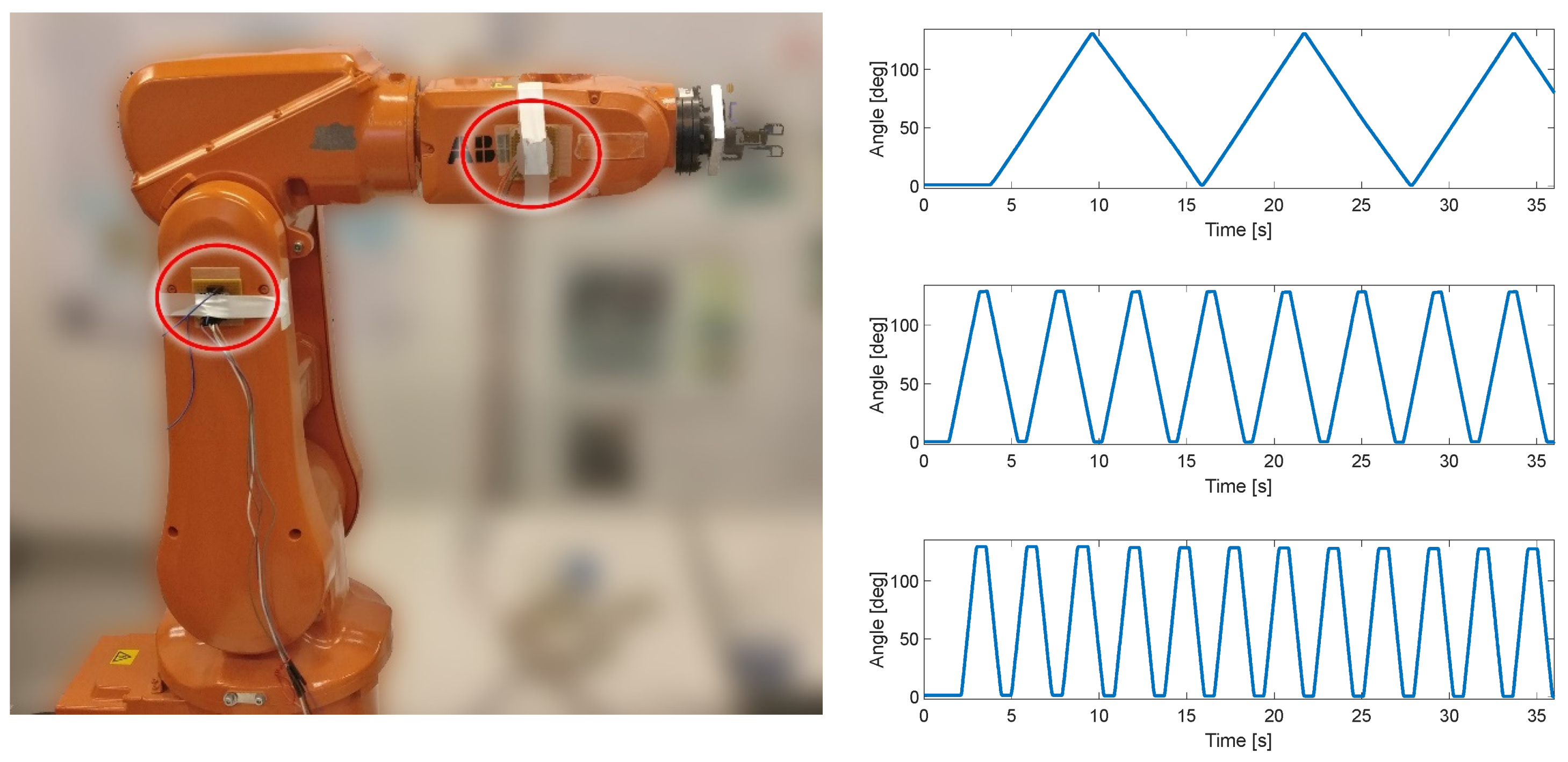
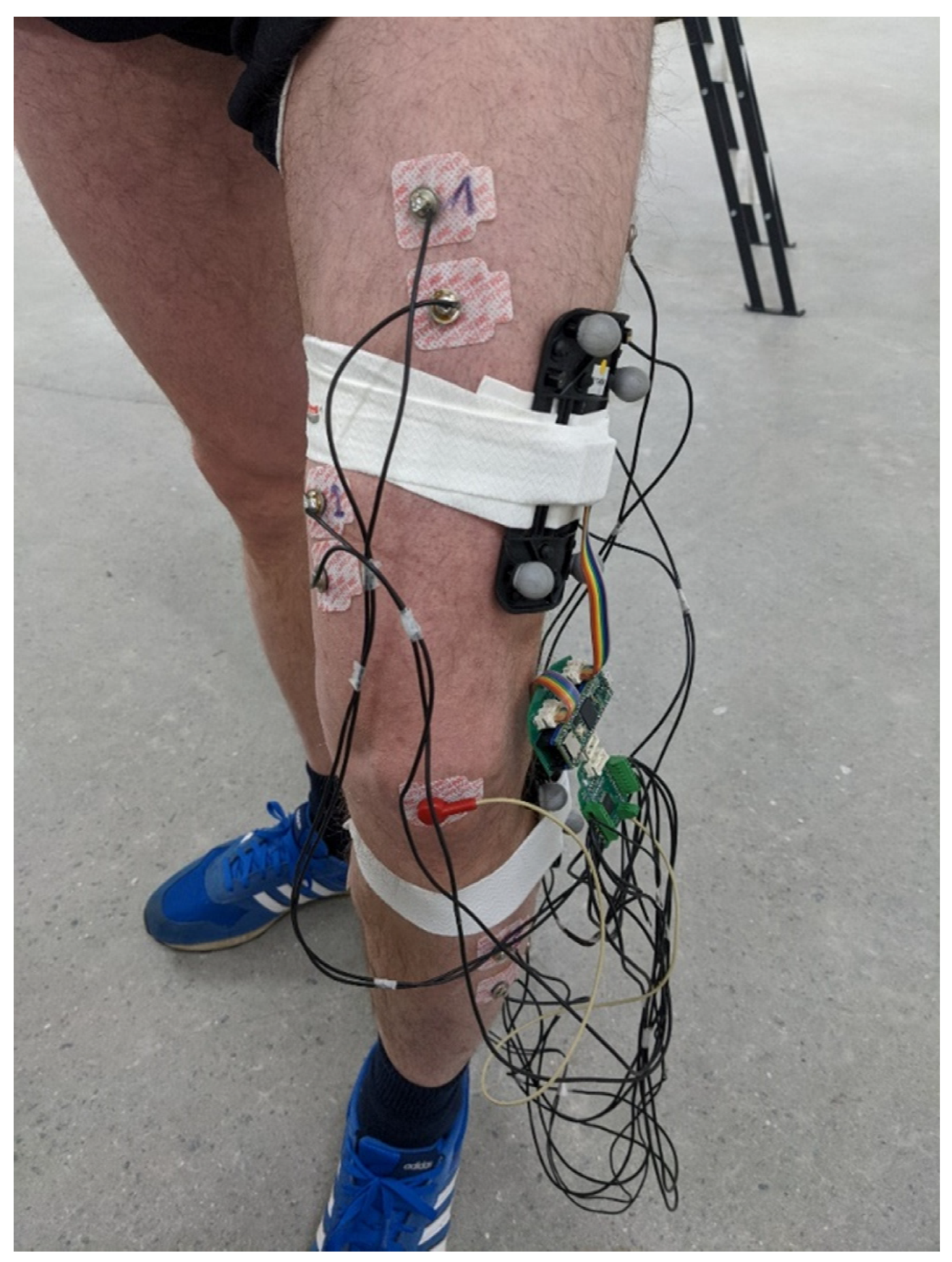
2.3. Evaluation
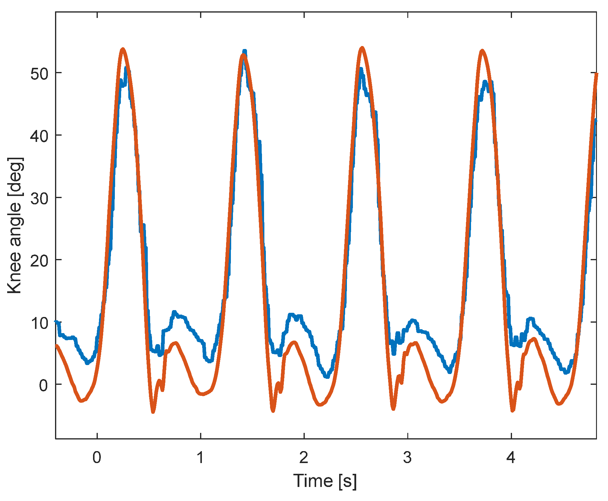
3. Results
4. Discussion
Author Contributions
Funding
Institutional Review Board Statement
Informed Consent Statement
Data Availability Statement
Acknowledgments
Conflicts of Interest
References
- Koman, L.A.; Smith, B.P.; Shilt, J.S. Cerebral Palsy. Lancet 2004, 363, 1619–1631. [Google Scholar] [CrossRef]
- Patel, D.R.; Neelakantan, M.; Pandher, K.; Merrick, J. Cerebral Palsy in Children: A Clinical Overview. Transl. Pediatr. 2020, 9, S125–S135. [Google Scholar] [CrossRef] [PubMed]
- Reddihough, D. Cerebral Palsy in Childhood. Aust. Fam. Physician 2011, 40, 192–196. [Google Scholar] [PubMed]
- Vitrikas, K.; Dalton, H.; Breish, D. Cerebral Palsy: An Overview. Am. Fam. Physician 2020, 101, 213–220. [Google Scholar] [CrossRef] [PubMed]
- O’Shea, T.M. Diagnosis, Treatment, and Prevention of Cerebral Palsy. Clin. Obstet. Gynecol. 2008, 51, 816–828. [Google Scholar] [CrossRef]
- Hägglund, G.; Hollung, S.J.; Ahonen, M.; Andersen, G.L.; Eggertsdóttir, G.; Gaston, M.S.; Jahnsen, R.; Jeglinsky-Kankainen, I.; Nordbye-Nielsen, K.; Tresoldi, I.; et al. Treatment of Spasticity in Children and Adolescents with Cerebral Palsy in Northern Europe: A CP-North Registry Study. BMC Neurol. 2021, 21, 276. [Google Scholar] [CrossRef]
- Hollung, S.J.; Hägglund, G.; Gaston, M.S.; Seid, A.K.; Lydersen, S.; Alriksson-Schmidt, A.I.; Andersen, G.L. Point Prevalence and Motor Function of Children and Adolescents with Cerebral Palsy in Scandinavia and Scotland: A CP-North Study. Dev. Med. Child. Neurol. 2021, 63, 721–728. [Google Scholar] [CrossRef]
- Hägglund, G.; Wagner, P. Spasticity of the Gastrosoleus Muscle Is Related to the Development of Reduced Passive Dorsiflexion of the Ankle in Children with Cerebral Palsy. Acta Orthop. 2011, 82, 744–748. [Google Scholar] [CrossRef]
- Novak, I.; Mcintyre, S.; Morgan, C.; Campbell, L.; Dark, L.; Morton, N.; Stumbles, E.; Wilson, S.-A.; Goldsmith, S. A Systematic Review of Interventions for Children with Cerebral Palsy: State of the Evidence. Dev. Med. Child. Neurol. 2013, 55, 885–910. [Google Scholar] [CrossRef]
- Thompson, A.J.; Jarrett, L.; Lockley, L.; Marsden, J.; Stevenson, V.L. Clinical Management of Spasticity. J. Neurol. Neurosurg. Psychiatry 2005, 76, 459–463. [Google Scholar] [CrossRef]
- Pavone, V.; Testa, G.; Restivo, D.A.; Cannavò, L.; Condorelli, G.; Portinaro, N.M.; Sessa, G. Botulinum Toxin Treatment for Limb Spasticity in Childhood Cerebral Palsy. Front. Pharmacol. 2016, 7, 183782. [Google Scholar] [CrossRef]
- Richardson, D. Physical Therapy in Spasticity. Eur. J. Neurol. 2002, 9, 17–22. [Google Scholar] [CrossRef]
- Wren, T.A.L.; Dryden, J.W.; Mueske, N.M.; Dennis, S.W.; Healy, B.S.; Rethlefsen, S.A. Comparison of 2 Orthotic Approaches in Children with Cerebral Palsy. Pediatr. Phys. Ther. 2015, 27, 218–226. [Google Scholar] [CrossRef]
- Fosang, A.L.; Galea, M.P.; McCoy, A.T.; Reddihough, D.S.; Story, I. Measures of Muscle and Joint Performance in the Lower Limb of Children with Cerebral Palsy. Dev. Med. Child. Neurol. 2003, 45, 664–670. [Google Scholar] [CrossRef]
- Stuberg, W.A.; Fuchs, R.H.; Miedaner, J.A. Reliability of Goniometric Measurements of Children with Cerebral Palsy. Dev. Med. Child. Neurol. 1988, 30, 657–666. [Google Scholar] [CrossRef] [PubMed]
- McDowell, B.C.; Hewitt, V.; Nurse, A.; Weston, T.; Baker, R. The Variability of Goniometric Measurements in Ambulatory Children with Spastic Cerebral Palsy. Gait Posture 2000, 12, 114–121. [Google Scholar] [CrossRef] [PubMed]
- Hancock, G.E.; Hepworth, T.; Wembridge, K. Accuracy and Reliability of Knee Goniometry Methods. J. Exp. Orthop. 2018, 5, 46. [Google Scholar] [CrossRef] [PubMed]
- van den Noort, J.C.; Scholtes, V.A.; Harlaar, J. Evaluation of Clinical Spasticity Assessment in Cerebral Palsy Using Inertial Sensors. Gait Posture 2009, 30, 138–143. [Google Scholar] [CrossRef]
- Darrah, J.; Wiart, L.; Gorter, J.W.; Law, M. Stability of Serial Range-of-Motion Measurements of the Lower Extremities in Children With Cerebral Palsy: Can We Do Better? Phys. Ther. 2014, 94, 987–995. [Google Scholar] [CrossRef]
- Carcreff, L.; Gerber, C.N.; Paraschiv-Ionescu, A.; De Coulon, G.; Newman, C.J.; Aminian, K.; Armand, S. Comparison of Gait Characteristics between Clinical and Daily Life Settings in Children with Cerebral Palsy. Sci. Rep. 2020, 10, 2091. [Google Scholar] [CrossRef]
- Kim, J.-Y.; Park, G.; Lee, S.-A.; Nam, Y. Analysis of Machine Learning-Based Assessment for Elbow Spasticity Using Inertial Sensors. Sensors 2020, 20, 1622. [Google Scholar] [CrossRef] [PubMed]
- Van Den Noort, J.C.; Ferrari, A.; Cutti, A.G.; Becher, J.G.; Harlaar, J. Gait Analysis in Children with Cerebral Palsy via Inertial and Magnetic Sensors. Med. Biol. Eng. Comput. 2013, 51, 377–386. [Google Scholar] [CrossRef]
- Bojanic, D.M.; Petrovacki-Balj, B.D.; Jorgovanovic, N.D.; Ilic, V.R. Quantification of Dynamic EMG Patterns during Gait in Children with Cerebral Palsy. J. Neurosci. Methods 2011, 198, 325–331. [Google Scholar] [CrossRef] [PubMed]
- Xu, K.; Mai, J.; He, L.; Yan, X.; Chen, Y. Surface Electromyography of Wrist Flexors and Extensors in Children with Hemiplegic Cerebral Palsy. PMR 2015, 7, 270–275. [Google Scholar] [CrossRef] [PubMed]
- Stackhouse, S.K.; Binder-Macleod, S.A.; Lee, S.C.K. Voluntary Muscle Activation, Contractile Properties, and Fatigability in Children with and without Cerebral Palsy. Muscle Nerve 2005, 31, 594–601. [Google Scholar] [CrossRef] [PubMed]
- Michelsen, J.S.; Lund, M.C.; Alkjær, T.; Finni, T.; Nielsen, J.B.; Lorentzen, J. Wearable Electromyography Recordings during Daily Life Activities in Children with Cerebral Palsy. Dev. Med. Child. Neurol. 2020, 62, 714–722. [Google Scholar] [CrossRef]
- Malesevic, J.; Kostic, M.; Kojic, V.; Dordevic, O.; Konstantinovic, L.; Keller, T.; Strbac, M. BEAGLE—A Kinematic Sensory System for Objective Hand Function Assessment in Technology-Mediated Rehabilitation. IEEE Trans. Neural Syst. Rehabil. Eng. 2021, 29, 1817–1826. [Google Scholar] [CrossRef]
- Siminovitch, D.J. Rotations in NMR: Part I. Euler-Rodrigues Parameters and Quaternions. Inc. Concepts Magn. Reson. 1997, 9, 149. [Google Scholar] [CrossRef]
- How Does One Verify the Quality of an EMG Signal?—Delsys. Available online: https://delsys.com/faq-items/how-does-one-verify-the-quality-of-an-emg-signal/ (accessed on 26 October 2023).
- Fan, B.; Li, Q.; Tan, T.; Kang, P.; Shull, P.B. Effects of IMU Sensor-to-Segment Misalignment and Orientation Error on 3-D Knee Joint Angle Estimation. IEEE Sens. J. 2022, 22, 2543–2552. [Google Scholar] [CrossRef]
- Lee, J.K.; Jeon, T.H. IMU-Based but Magnetometer-Free Joint Angle Estimation of Constrained Links. In Proceedings of the IEEE Sensors 2018, New Delhi, India, 28–31 October 2018. [Google Scholar] [CrossRef]
- Bakhshi, S.; Mahoor, M.H.; Davidson, B.S. Development of a Body Joint Angle Measurement System Using IMU Sensors. In Proceedings of the Annual International Conference of the IEEE Engineering in Medicine and Biology Society, EMBS 2011, Boston, MA, USA, 30 August–3 September 2011; pp. 6923–6926. [Google Scholar] [CrossRef]
- Seel, T.; Raisch, J.; Schauer, T. IMU-Based Joint Angle Measurement for Gait Analysis. Sensors 2014, 14, 6891–6909. [Google Scholar] [CrossRef]
- Williamson, R.; Andrews, B.J. Detecting Absolute Human Knee Angle and Angular Velocity Using Accelerometers and Rate Gyroscopes. Med. Biol. Eng. Comput. 2001, 39, 294–302. [Google Scholar] [CrossRef]
- Schulze, M.; Liu, T.H.; Xie, J.; Zhang, W.; Wolf, K.H.; Calliess, T.; Windhagen, H.; Marschollek, M. Unobtrusive Ambulatory Estimation of Knee Joint Angles during Walking Using Gyroscope and Accelerometer Data—A Preliminary Evaluation Study. In Proceedings of the IEEE-EMBS International Conference on Biomedical and Health Informatics: Global Grand Challenge of Health Informatics, BHI 2012, Hong Kong, China, 5–7 January 2012; pp. 559–562. [Google Scholar] [CrossRef]
- Tadano, S.; Takeda, R.; Miyagawa, H. Three Dimensional Gait Analysis Using Wearable Acceleration and Gyro Sensors Based on Quaternion Calculations. Sensors 2013, 13, 9321–9343. [Google Scholar] [CrossRef]
- Dorschky, E.; Nitschke, M.; Seifer, A.K.; van den Bogert, A.J.; Eskofier, B.M. Estimation of Gait Kinematics and Kinetics from Inertial Sensor Data Using Optimal Control of Musculoskeletal Models. J. Biomech. 2019, 95, 109278. [Google Scholar] [CrossRef]
- Takeda, R.; Tadano, S.; Natorigawa, A.; Todoh, M.; Yoshinari, S. Gait Posture Estimation Using Wearable Acceleration and Gyro Sensors. J. Biomech. 2009, 42, 2486–2494. [Google Scholar] [CrossRef] [PubMed]
- Ohtaki, Y.; Sagawa, K.; Inooka, H. A Method for Gait Analysis in a Daily Living Environment by Body-Mounted Instruments. JSME Int. J. Ser. C Mech. Syst. Mach. Elem. Manuf. 2001, 44, 1125–1132. [Google Scholar] [CrossRef]
- Hemingway, E.G.; O’Reilly, O.M. Perspectives on Euler Angle Singularities, Gimbal Lock, and the Orthogonality of Applied Forces and Applied Moments. Multibody Syst. Dyn. 2018, 44, 31–56. [Google Scholar] [CrossRef]
- Yi, C.; Wei, B.; Ding, Z.; Yang, C.; Chen, Z.; Jiang, F. A Self-Aligned Method of IMU-Based 3-DoF Lower-Limb Joint Angle Estimation. IEEE Trans. Instrum. Meas. 2022, 71, 4007310. [Google Scholar] [CrossRef]
- Niswander, W.; Wang, W.; Kontson, K. Optimization of IMU Sensor Placement for the Measurement of Lower Limb Joint Kinematics. Sensors 2020, 20, 5993. [Google Scholar] [CrossRef] [PubMed]
- Merletti, R.; Botter, A.; Barone, U. Detection and Conditioning of Surface EMG Signals. In Surface Electromyography: Physiology, Engineering and Applications; Wiley Online Library: Hoboken, NJ, USA, 2016; pp. 1–37. [Google Scholar] [CrossRef]
- Liu, H.; Schultz, T. A Wearable Real-Time Human Activity Recognition System Using Biosensors Integrated into a Knee Bandage. In Proceedings of the 12th International Joint Conference on Biomedical Engineering Systems and Technologies, Prague, Czech Republic, 22–24 February 2019; SCITEPRESS—Science and Technology Publications: Setúbal, Portugal, 2019; pp. 47–55. [Google Scholar]
- Liu, H.; Xue, T.; Schultz, T. On a Real Real-Time Wearable Human Activity Recognition System. In Proceedings of the 16th International Joint Conference on Biomedical Engineering Systems and Technologies, Lisbon, Portugal, 16–18 February 2023; SCITEPRESS—Science and Technology Publications: Setúbal, Portugal, 2023; pp. 711–720. [Google Scholar]
- Liu, H.; Schultz, T. ASK: A Framework for Data Acquisition and Activity Recognition. In Proceedings of the BIOSIGNALS 2018—11th International Conference on Bio-Inspired Systems and Signal Processing, Proceedings; Part of 11th International Joint Conference on Biomedical Engineering Systems and Technologies, BIOSTEC 2018, Madeira, Portugal, 19–21 January 2018; SciTePress: Setúbal, Portugal, 2018; Volume 4, pp. 262–268. [Google Scholar]


| FRE [°] | SSE | R-Squared | RMSE | |
|---|---|---|---|---|
| Slow | 0.44 | 8.9 | 0.99 | 0.15 |
| Medium | 0.92 | 2.1 | 0.99 | 0.11 |
| Fast | 0.7 | 1.2 | 0.99 | 0.12 |
| Slow-Tilt | 0.25 | 5.5 | 0.99 | 0.09 |
| Medium-Tilt | 0.81 | 0.5 | 0.99 | 0.05 |
| Fast-Tilt | 0.41 | 1.1 | 0.99 | 0.12 |
Disclaimer/Publisher’s Note: The statements, opinions and data contained in all publications are solely those of the individual author(s) and contributor(s) and not of MDPI and/or the editor(s). MDPI and/or the editor(s) disclaim responsibility for any injury to people or property resulting from any ideas, methods, instructions or products referred to in the content. |
© 2023 by the authors. Licensee MDPI, Basel, Switzerland. This article is an open access article distributed under the terms and conditions of the Creative Commons Attribution (CC BY) license (https://creativecommons.org/licenses/by/4.0/).
Share and Cite
Malesevic, N.; Svensson, I.; Hägglund, G.; Antfolk, C. An Integrated Approach for Real-Time Monitoring of Knee Dynamics with IMUs and Multichannel EMG. Sensors 2023, 23, 8955. https://doi.org/10.3390/s23218955
Malesevic N, Svensson I, Hägglund G, Antfolk C. An Integrated Approach for Real-Time Monitoring of Knee Dynamics with IMUs and Multichannel EMG. Sensors. 2023; 23(21):8955. https://doi.org/10.3390/s23218955
Chicago/Turabian StyleMalesevic, Nebojsa, Ingrid Svensson, Gunnar Hägglund, and Christian Antfolk. 2023. "An Integrated Approach for Real-Time Monitoring of Knee Dynamics with IMUs and Multichannel EMG" Sensors 23, no. 21: 8955. https://doi.org/10.3390/s23218955
APA StyleMalesevic, N., Svensson, I., Hägglund, G., & Antfolk, C. (2023). An Integrated Approach for Real-Time Monitoring of Knee Dynamics with IMUs and Multichannel EMG. Sensors, 23(21), 8955. https://doi.org/10.3390/s23218955