
Deep Learning-Based Link Quality Estimation for RIS-Assisted UAV-Enabled Wireless Communications System

 , , , ,
  and
and
Abstract
:1. Introduction
- (1)
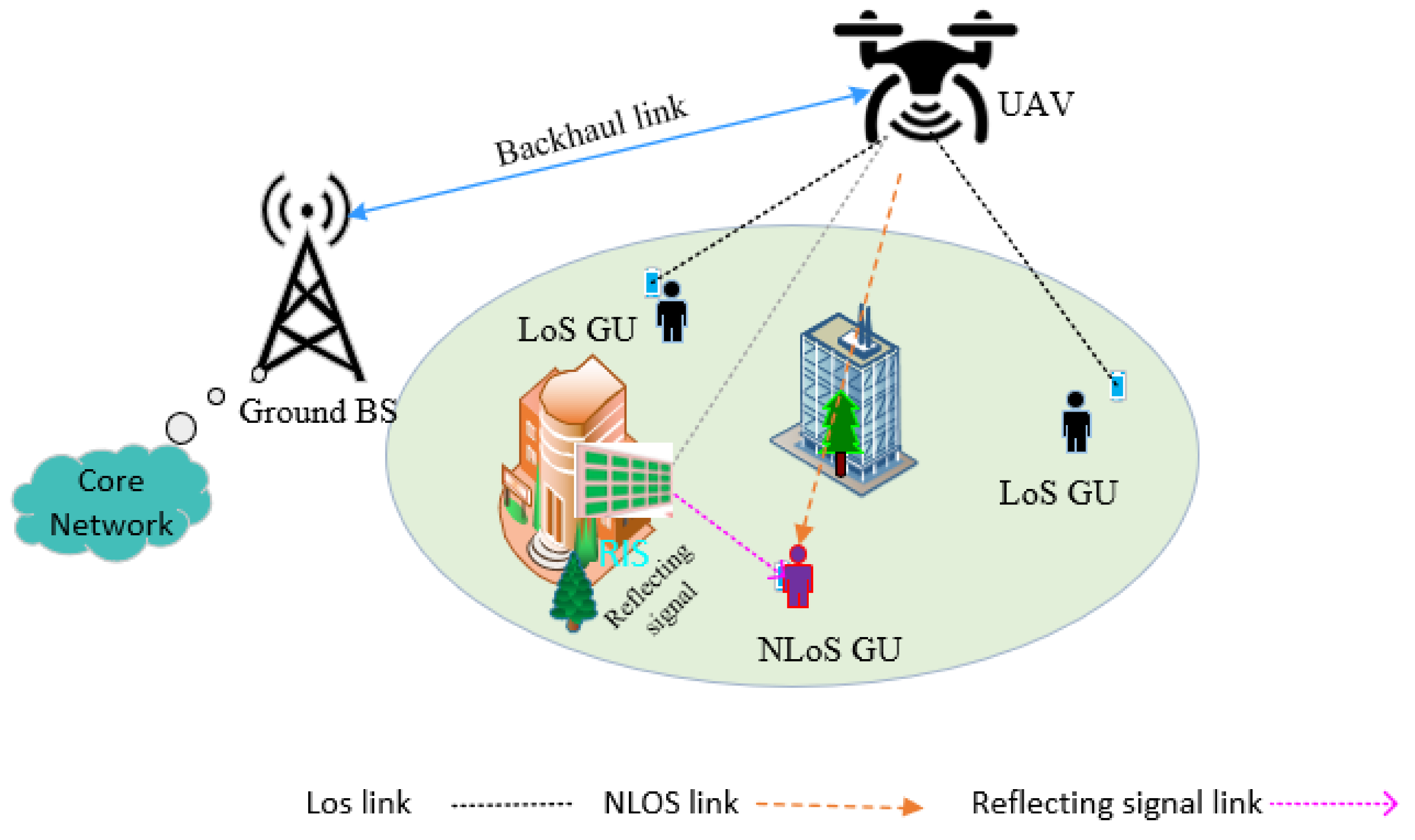
- Numerous studies in the literature assess the quality of links in communication systems that utilize UAVs [11,12,13]. This article accurately estimates link quality in UAV-based communication systems by considering slow fading and fast fading while integrating RIS. We create a communication system for urban users integrating RIS and UAV. This system effectively addresses issues with signal propagation between UAVs and users in urban environments, accounting for building blockage effects.
- (2)
- We propose a GRU-based model for estimating link quality in UAV-assisted wireless networks by leveraging the full capabilities of UAV and RIS, including considering the UAV trajectory and RIS passive phase shift.
- (3)
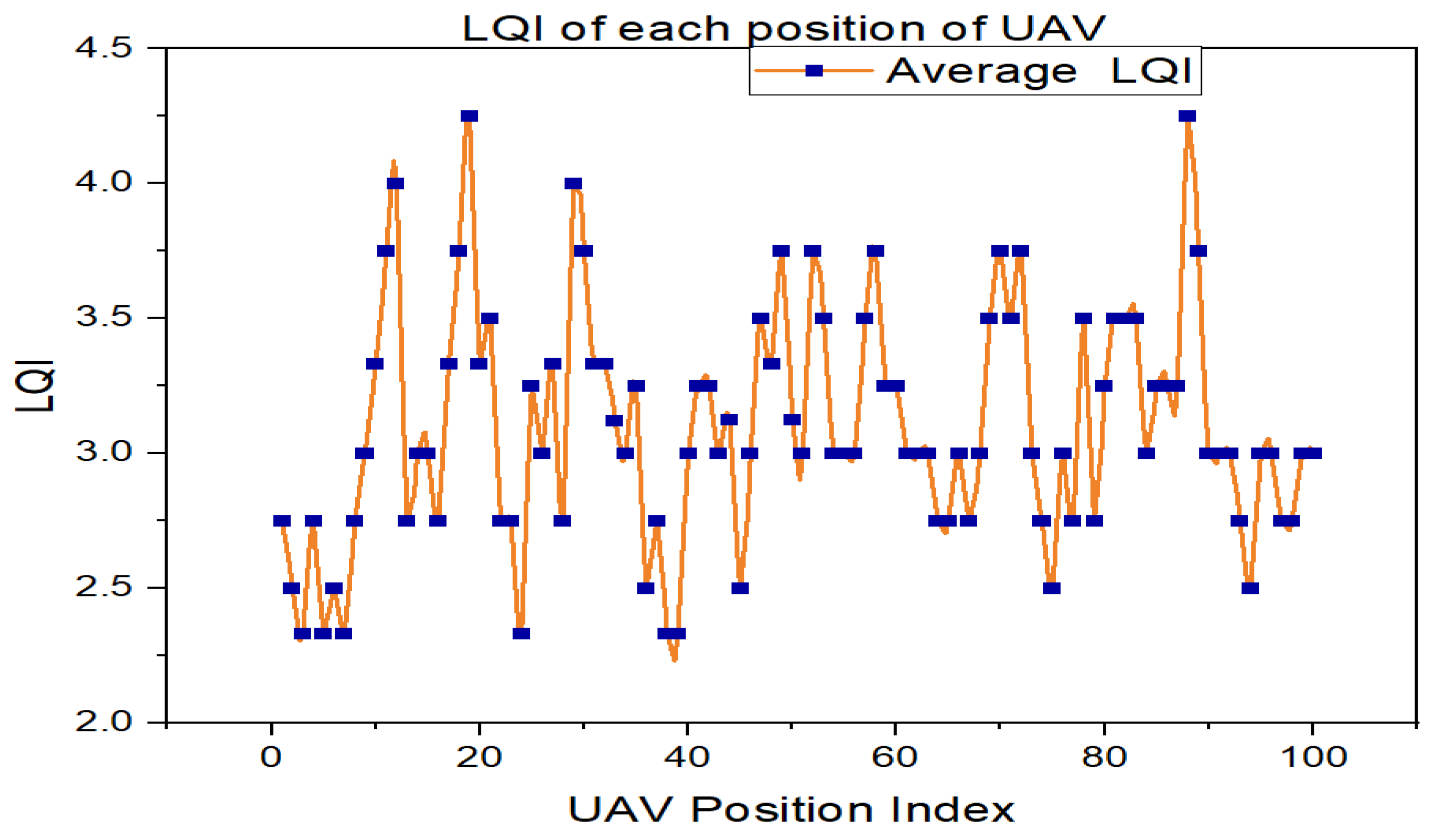
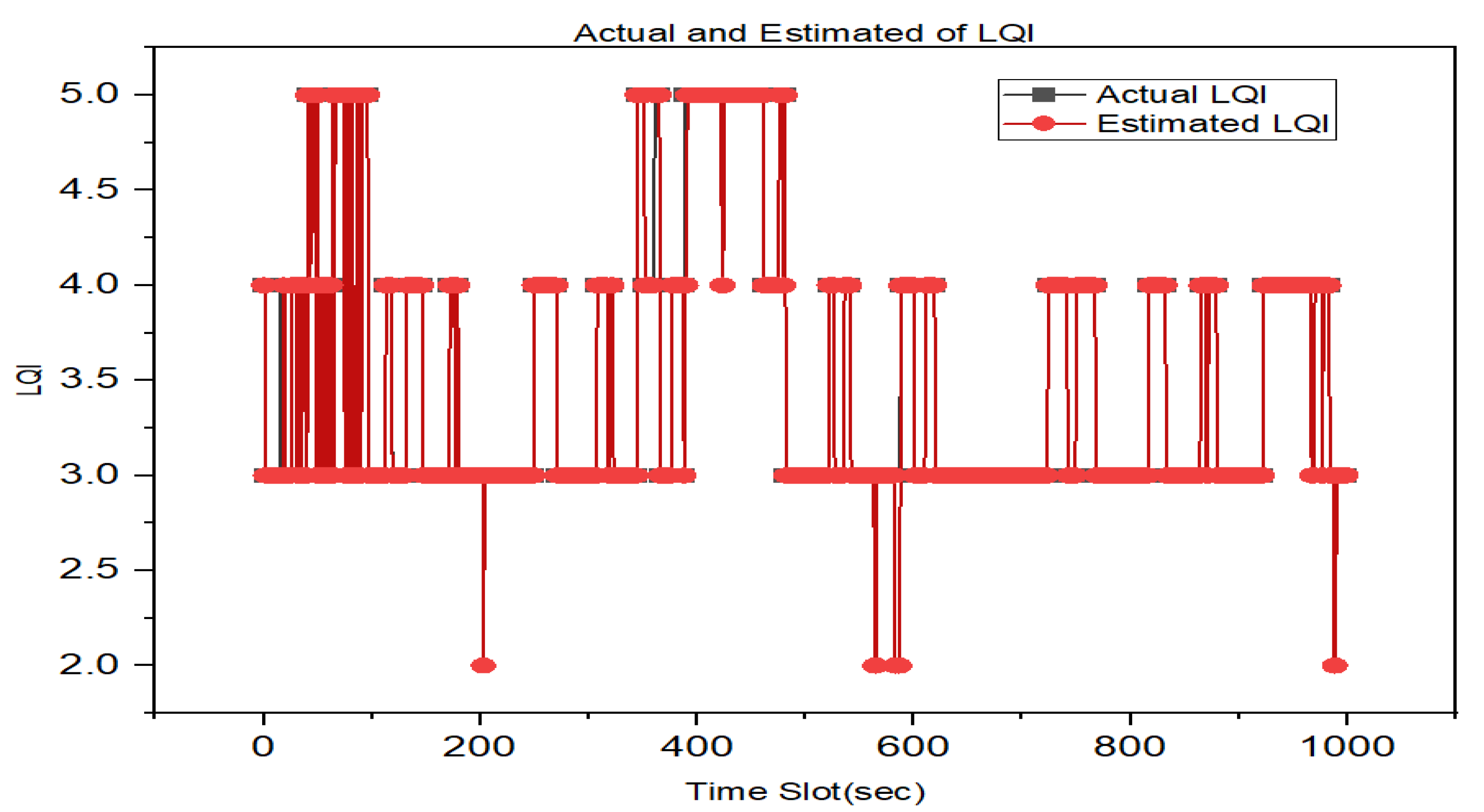
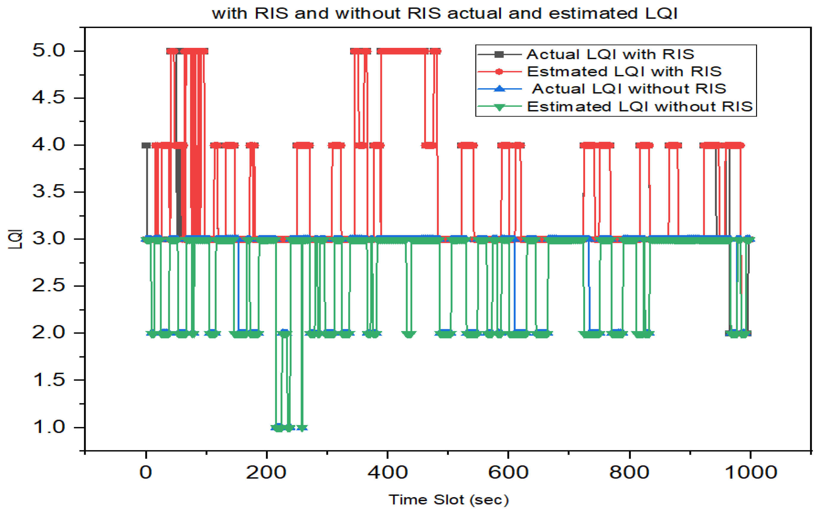
- We provide numerical results that demonstrate the significance of the proposed model in terms of accuracy for estimating the link quality with the assistance of RIS in an RIS-assisted UAV communication system.
2. Related Work
3. System Model
3.1. Channel Model
3.1.1. UAV-GU Link
3.1.2. UAV-RIS-GU Link
4. Proposed Method
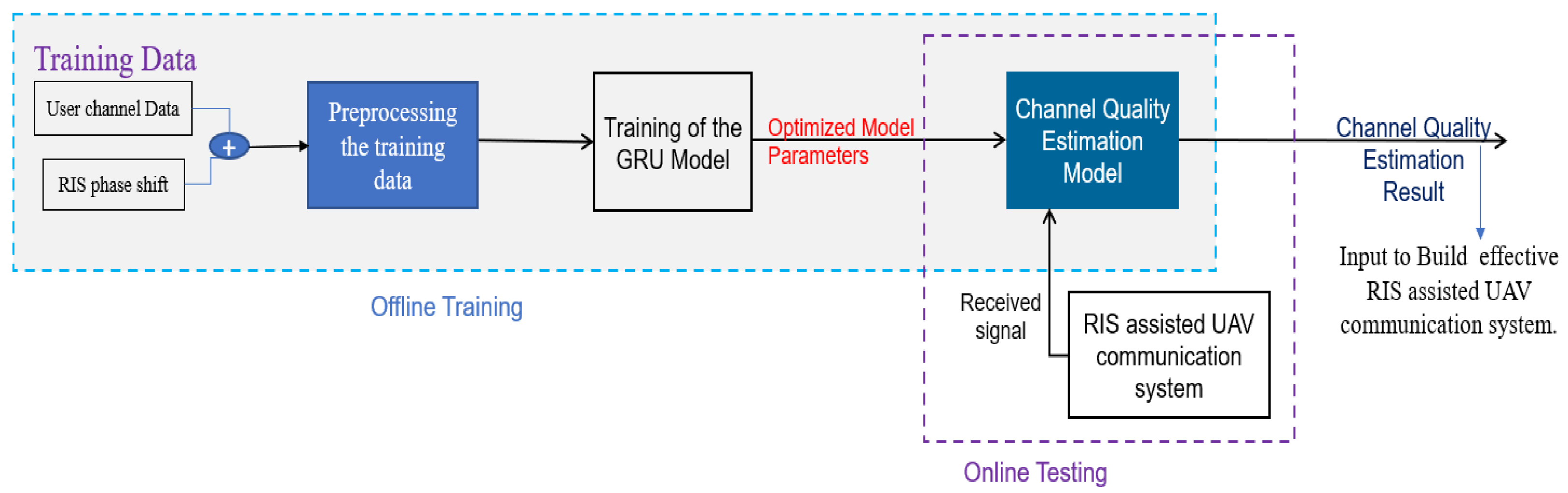
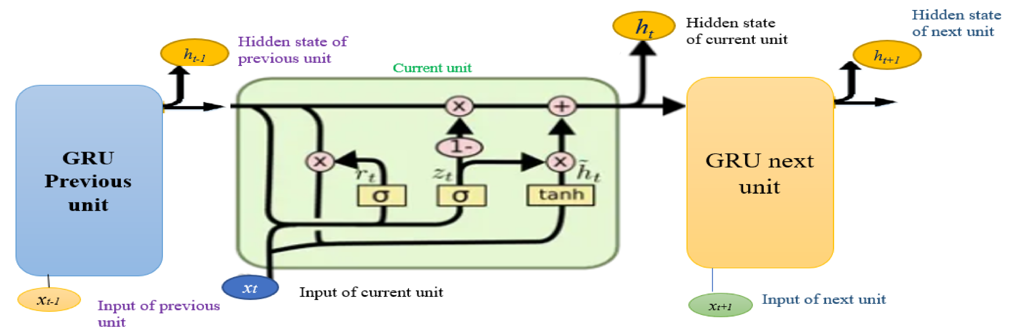
4.1. GRU-Based Link Quality Estimation Model
4.1.1. User Channel Data Simulation
| Algorithm 1: RIS Phase Shift Algorithm. |
| Input: RIS parameter value Output: Final configuration of the RIS elements 1: = 0 2: For RIS element: = 1 to N do // N is elements of RIS 3: using Equation (9) // compute the reflection coefficient 4: Compute 5: Update 6: end for |
4.1.2. Data Preprocessing
| Algorithm 2: Preprocessing data. |
| Input: User channel data and RIS phase shift Output: Return filled missing values, labeled data, and normalized values. // Step 1. Filling Missing Values: 1: For future of dataset: =fd to Fd // fd is future of da-taset 2: For sample: = sd to Sd // sd is sample of dataset 3: If fd is missing: 4: Replace the missing value by −6 5: end if 6: end for 7: end for // Step 2. Data Labeling: 1: For sample: = sd to Sd 2: Label the SNR to LQI based on the above range 3: Assign the corresponding label to the sample 4: end for // Step 3. Data Normalization: 1: For the future of the dataset: =fd to Fd 2: For sample: = sd to Sd 3: Normalize the value of the feature using the (16) 4: end for 5: end for |
4.1.3. Build Link Quality Estimation Model
| Algorithm 3: GRU-based LQE Method. |
| Input: preprocessed dataset. Output: Optimized w and b for training the LQE model. // w is weight, b is bias 1: Initialize the learning parameters of GRU. 2: For epoch: =1 to T do 3: LQE model Training; 4: GRU network weights and bias need to be updated; 5: end for |
| Algorithm 4: Online LQE model. |
| 1: load the Algorithm 3 model: 2: For each TS t do 3: received SNR from user; 4: estimate link quality 5: t = t + 1; 6: end for |
5. Results
5.1. Simulation Setup
5.2. Results and Discussion
5.3. Computational Time and Complexity
6. Conclusions
Author Contributions
Funding
Institutional Review Board Statement
Informed Consent Statement
Data Availability Statement
Acknowledgments
Conflicts of Interest
References
- Balador, A.; Kouba, A.; Cassioli, D.; Foukalas, F.; Severino, R.; Stepanova, D.; Agosta, G.; Xie, J.; Pomante, L.; Mongelli, M.; et al. Wireless Communication Technologies for Safe Cooperative Cyber Physical Systems. Sensors 2018, 18, 4075. [Google Scholar] [CrossRef] [PubMed]
- Zeng, Y.; Zhang, R.; Lim, T.J. Wireless Communications with Unmanned Aerial Vehicles: Opportunities and Challenges. IEEE Commun. Mag. 2016, 54, 36–42. [Google Scholar] [CrossRef]
- Telli, K.; Kraa, O.; Himeur, Y.; Ouamane, A.; Boumehraz, M.; Atalla, S.; Mansoor, W. A Comprehensive Review of Recent Research Trends on Unmanned Aerial Vehicles (UAVs). Systems 2023, 11, 400. [Google Scholar] [CrossRef]
- Alshaibani, W.T.; Shayea, I.; Caglar, R.; Din, J.; Daradkeh, Y.I. Mobility Management of Unmanned Aerial Vehicles in Ultra–Dense Heterogeneous Networks. Sensors 2022, 22, 6013. [Google Scholar] [CrossRef] [PubMed]
- Fan, X.; Liu, M.; Chen, Y.; Sun, S.; Li, Z.; Guo, X. RIS-Assisted UAV for Fresh Data Collection in 3D Urban Environments: A Deep Reinforcement Learning Approach. IEEE Trans. Veh. Technol. 2023, 72, 632–647. [Google Scholar] [CrossRef]
- ElMossallamy, M.A.; Zhang, H.; Song, L.; Seddik, K.G.; Han, Z.; Li, G.Y. Reconfigurable Intelligent Surfaces for Wireless Communications: Principles, Challenges, and Opportunities. IEEE Trans. Cogn. Commun. Netw. 2020, 6, 990–1002. [Google Scholar] [CrossRef]
- Park, K.W.; Kim, H.M.; Shin, O.S. A Survey on Intelligent-Reflecting-Surface-Assisted UAV Communications. Energies 2022, 15, 5143. [Google Scholar] [CrossRef]
- Pogaku, A.C.; Do, D.T.; Lee, B.M.; Nguyen, N.D. UAV-Assisted RIS for Future Wireless Communications: A Survey on Optimization and Performance Analysis. IEEE Access 2022, 10, 16320–16336. [Google Scholar] [CrossRef]
- Abdalla, A.S.; Rahman, T.F.; Marojevic, V. UAVs with Reconfigurable Intelligent Surfaces: Applications, Challenges, and Opportunities. arXiv 2020, arXiv:2012.04775. [Google Scholar]
- Abbas, Z.; Liu, X.; Khan, S.S.; Foster, E.D.; Larkin, S. A Survey: Future Smart Cities Based on Advance Control of Unmanned Aerial Vehicles (UAVs). Appl. Sci. 2023, 13, 9881. [Google Scholar] [CrossRef]
- Ren, H.; Zhang, Z.; Peng, Z.; Li, L.; Pan, C. Energy Minimization in RIS-Assisted UAV-Enabled Wireless Power Transfer Systems. IEEE Internet Things J. 2023, 10, 5794–5809. [Google Scholar] [CrossRef]
- Mohsan, S.A.H.; Othman, N.Q.H.; Li, Y.; Alsharif, M.H.; Khan, M.A. Unmanned Aerial Vehicles (UAVs): Practical Aspects, Applications, Open Challenges, Security Issues, and Future Trends. Intell. Serv. Robot. 2023, 16, 109–137. [Google Scholar] [CrossRef] [PubMed]
- Shi, B.; Wang, Y.; Li, D.; Cai, W.; Lin, J.; Zhang, S.; Shi, W.; Yan, S.; Shu, F. STAR-RIS-UAV-Aided Coordinated Multipoint Cellular System for Multi-User Networks. Drones 2023, 7, 403. [Google Scholar] [CrossRef]
- Asif, M.; Ihsan, A.; Khan, W.U.; Ranjha, A.; Zhang, S.; Wu, S.X. Energy-Efficient Beamforming and Resource Optimization for AmBSC-Assisted Cooperative NOMA IoT Networks. IEEE Internet Things J. 2022, 10, 12434–12448. [Google Scholar] [CrossRef]
- Luo, X.; Liu, L.; Shu, J.; Al-Kali, M. Link Quality Estimation Method for Wireless Sensor Networks Based on Stacked Autoencoder. IEEE Access 2019, 7, 21572–21583. [Google Scholar] [CrossRef]
- Cerar, G.; Yetgin, H.; Mohorčič, M.; Fortuna, C. On Designing a Machine Learning Based Wireless Link Quality Classifier. In Proceedings of the 2020 IEEE 31st Annual International Symposium on Personal, Indoor and Mobile Radio Communications, London, UK, 31 August –3 September 2020. [Google Scholar] [CrossRef]
- Dargie, W.; Wen, J. A Link Quality Estimation Model for a Joint Deployment of Unmanned Aerial Vehicles and Wireless Sensor Networks. In Proceedings of the 2021 International Conference on Computer Communications and Networks (ICCCN), Athens, Greece, 19–22 July 2021. [Google Scholar]
- Tarekegn, G.B.; Juang, R.T.; Lin, H.P.; Munaye, Y.Y.; Wang, L.C.; Jeng, S.S. Channel Quality Estimation in 3D Drone Base Station for Future Wireless Network. In Proceedings of the 2021 30th Wireless and Optical Communications Conference, WOCC 2021, Institute of Electrical and Electronics Engineers Inc., Taipei, Taiwan, 7–8 October 2021; pp. 236–239. [Google Scholar]
- Tarekegn, G.B.; Juang, R.T.; Lin, H.P.; Munaye, Y.Y.; Wang, L.C.; Bitew, M.A. Deep-Reinforcement-Learning-Based Drone Base Station Deployment for Wireless Communication Services. IEEE Internet Things J. 2022, 9, 21899–21915. [Google Scholar] [CrossRef]
- Kang, H.; Joung, J.; Kang, J. A Study on Probabilistic Line-of-Sight Air-to-Ground Channel Models. In Proceedings of the 2019 34th International Technical Conference on Circuits/Systems, Computers and Communications (ITC-CSCC), JeJu, Republic of Korea, 23–26 June 2019. [Google Scholar]
- Van Brandt, S.; Van Thielen, R.; Verhaevert, J.; Van Hecke, T.; Rogier, H. Characterization of Path Loss and Large-Scale Fading for Rapid Intervention Team Communication in Underground Parking Garages. Sensors 2019, 19, 2431. [Google Scholar] [CrossRef]
- Ma, X.; Chen, Z.; Chen, W.; Li, Z.; Chi, Y.; Han, C.; Li, S. Joint Channel Estimation and Data Rate Maximization for Intelligent Reflecting Surface Assisted Terahertz MIMO Communication Systems. IEEE Access 2020, 8, 99565–99581. [Google Scholar] [CrossRef]
- Kim, J.; Yu, H.; Kang, X.; Joung, J. Discrete Phase Shifts of Intelligent Reflecting Surface Systems Considering Network Overhead. Entropy 2022, 24, 1753. [Google Scholar] [CrossRef]
- Vlavianos, A.; Law, L.K.; Broustis, I.; Krishnamurthy, S.V.; Faloutsos, M. Assessing Link Quality in IEEE 802.11 Wireless Networks: Which Is the Right Metric? In Proceedings of the IEEE International Symposium on Personal, Indoor and Mobile Radio Communications, PIMRC, Cannes, France, 15–18 September 2008. [Google Scholar]
- Yue, B.; Fu, J.; Liang, J. Residual Recurrent Neural Networks for Learning Sequential Representations. Information 2018, 9, 56. [Google Scholar] [CrossRef]
- Tarekegn, G.B.; Tai, L.C.; Lin, H.P.; Tesfaw, B.A.; Juang, R.T.; Hsu, H.C.; Huang, K.L.; Singh, K. Applying T-Distributed Stochastic Neighbor Embedding for Improving Fingerprinting-Based Localization System. IEEE Sens. Lett. 2023, 7, 6005004. [Google Scholar] [CrossRef]
- Tarekegn, G.B.; Juang, R.T.; Lin, H.P.; Tai, L.C.; Munaye, Y.Y.; Bitew, M.A. SRCLoc: Synthetic Radio Map Construction Method for Fingerprinting Outdoor Localization in Hybrid Networks. IEEE Sens. J. 2022, 22, 15574–15583. [Google Scholar] [CrossRef]
- Blume, S.; Benedens, T.; Schramm, D. Hyperparameter Optimization Techniques for Designing Software Sensors Based on Artificial Neural Networks. Sensors 2021, 21, 8435. [Google Scholar] [CrossRef] [PubMed]
Disclaimer/Publisher’s Note: The statements, opinions, and data contained in all publications are solely those of the individual author(s) and contributor(s) and not of MDPI and/or the editor(s). MDPI and/or the editor(s) disclaim responsibility for any injury to people or property resulting from any ideas, methods, instructions, or products referred to in the content. |


| Parameter | Value |
|---|---|
| Transmit power p | 0.1 W |
| Noise Power No | −80 dB |
| Path loss at 1 m α | −20 dB |
| Path loss for LoS ηLoS | 0.2 dB |
| Path loss for NLoS ηNLoS | 21 dB |
| Carrier frequency fc | 2 GHz |
| Rician factor K1 | 3 dB |
| Speed of light c | 3 × 10⁸ m/s |
| Path loss RIS-GU link β | 2.8 |
| Number of RIS elements N | 9 |
| quantization bits b | 4 bits |
| Parameter | Value |
|---|---|
| Number of hidden layers | 3 (128, 64, 32 neurons) |
| Dropout | 0.2 |
| Batch size | 32 |
| Learning rate | 0.001 |
| Loss function | Cross-entropy |
| Optimization algorithm | Adam |
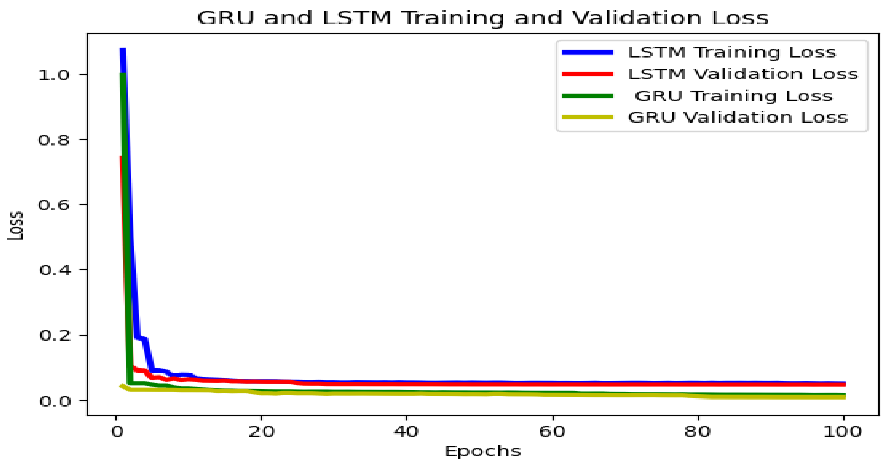
| Number of epochs | 100 |
| Performance Metrics | LSTM | GRU |
|---|---|---|
| Accuracy | 0.95 | 0.96 |
| Cross-entropy | 0.12 | 0.062 |
Disclaimer/Publisher’s Note: The statements, opinions and data contained in all publications are solely those of the individual author(s) and contributor(s) and not of MDPI and/or the editor(s). MDPI and/or the editor(s) disclaim responsibility for any injury to people or property resulting from any ideas, methods, instructions or products referred to in the content. |
© 2023 by the authors. Licensee MDPI, Basel, Switzerland. This article is an open access article distributed under the terms and conditions of the Creative Commons Attribution (CC BY) license (https://creativecommons.org/licenses/by/4.0/).
Share and Cite
Tesfaw, B.A.; Juang, R.-T.; Tai, L.-C.; Lin, H.-P.; Tarekegn, G.B.; Nathanael, K.W. Deep Learning-Based Link Quality Estimation for RIS-Assisted UAV-Enabled Wireless Communications System. Sensors 2023, 23, 8041. https://doi.org/10.3390/s23198041
Tesfaw BA, Juang R-T, Tai L-C, Lin H-P, Tarekegn GB, Nathanael KW. Deep Learning-Based Link Quality Estimation for RIS-Assisted UAV-Enabled Wireless Communications System. Sensors. 2023; 23(19):8041. https://doi.org/10.3390/s23198041
Chicago/Turabian StyleTesfaw, Belayneh Abebe, Rong-Terng Juang, Li-Chia Tai, Hsin-Piao Lin, Getaneh Berie Tarekegn, and Kabore Wendenda Nathanael. 2023. "Deep Learning-Based Link Quality Estimation for RIS-Assisted UAV-Enabled Wireless Communications System" Sensors 23, no. 19: 8041. https://doi.org/10.3390/s23198041
APA StyleTesfaw, B. A., Juang, R.-T., Tai, L.-C., Lin, H.-P., Tarekegn, G. B., & Nathanael, K. W. (2023). Deep Learning-Based Link Quality Estimation for RIS-Assisted UAV-Enabled Wireless Communications System. Sensors, 23(19), 8041. https://doi.org/10.3390/s23198041