
Frequency-Selective Surface-Based MIMO Antenna Array for 5G Millimeter-Wave Applications


 ,
,  ,
,  ,
,  ,
,  ,
, 
Abstract
1. Introduction
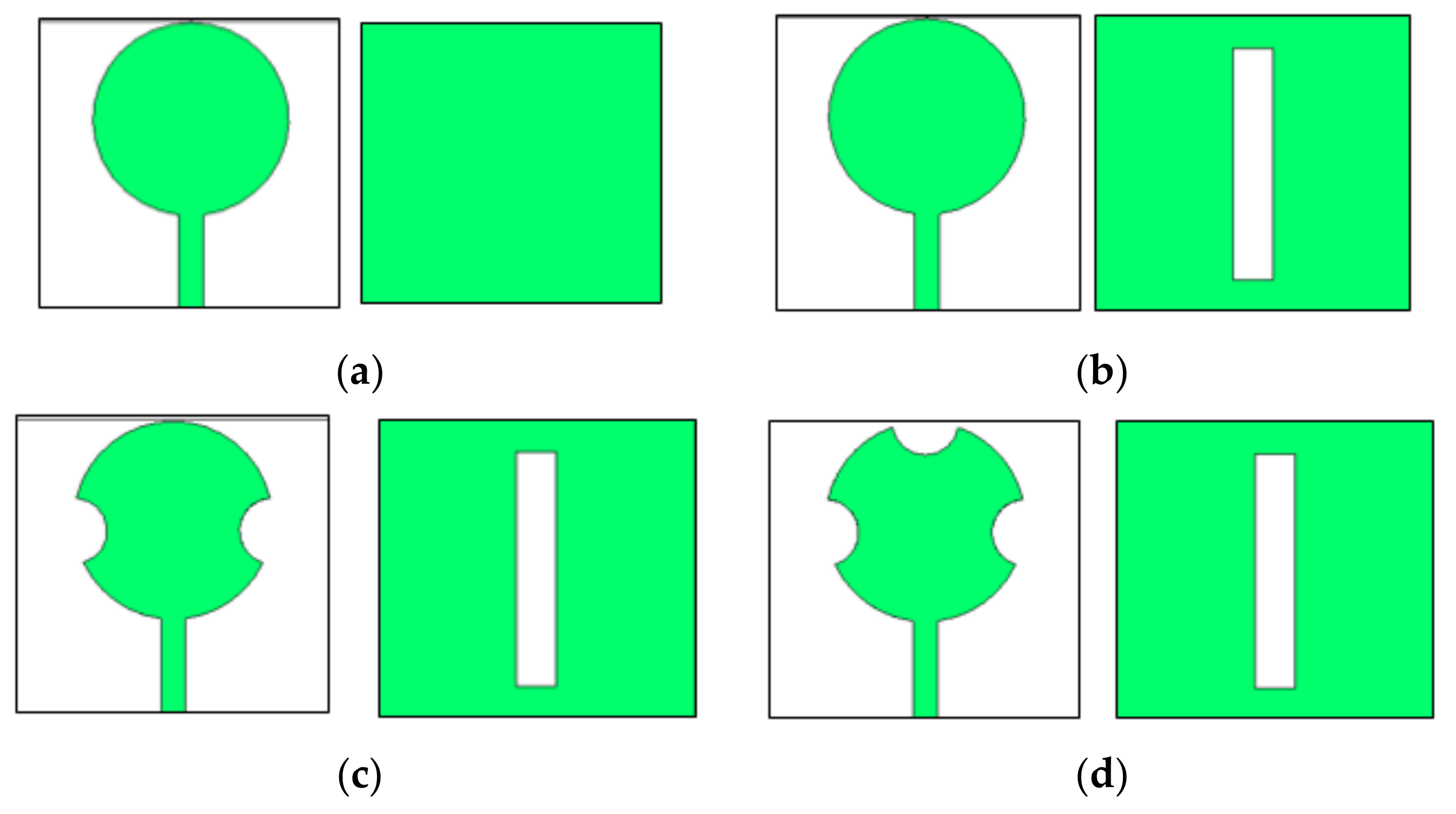
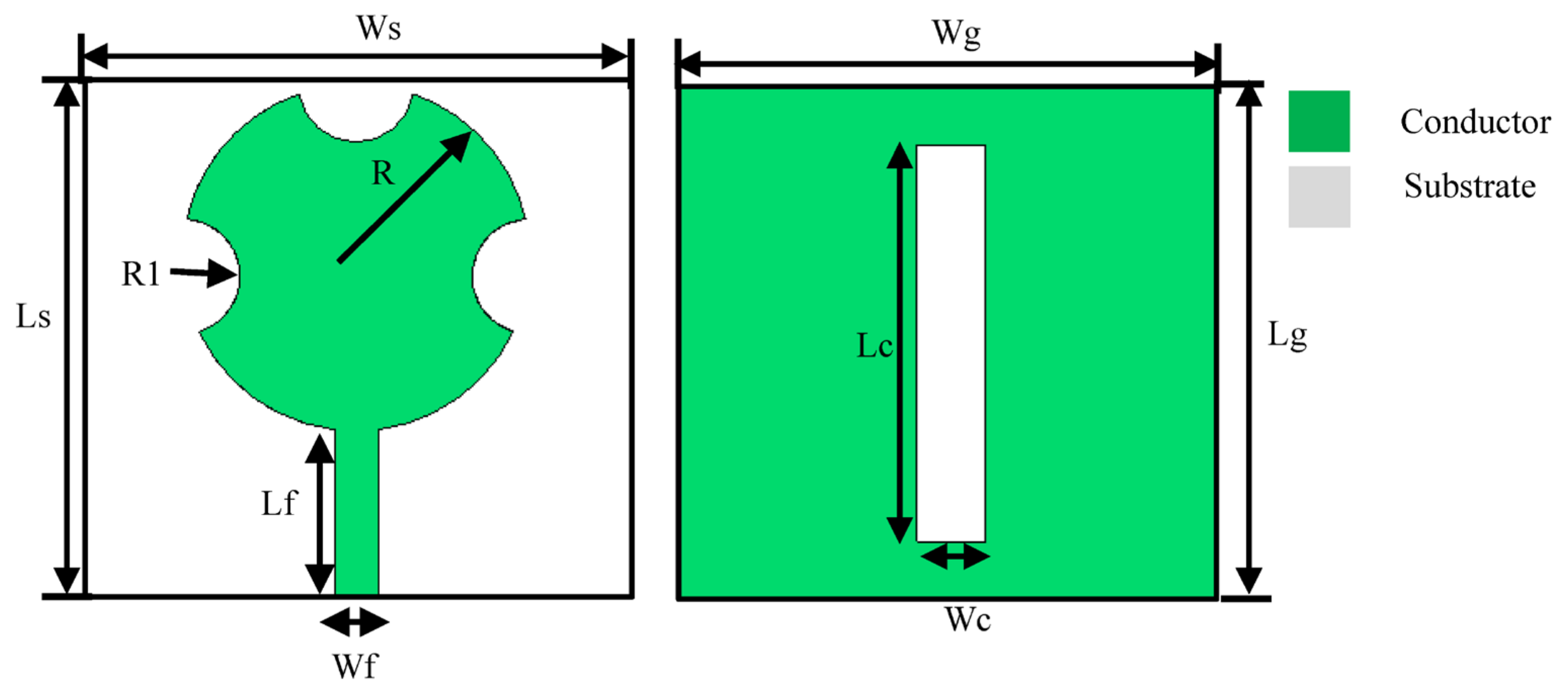
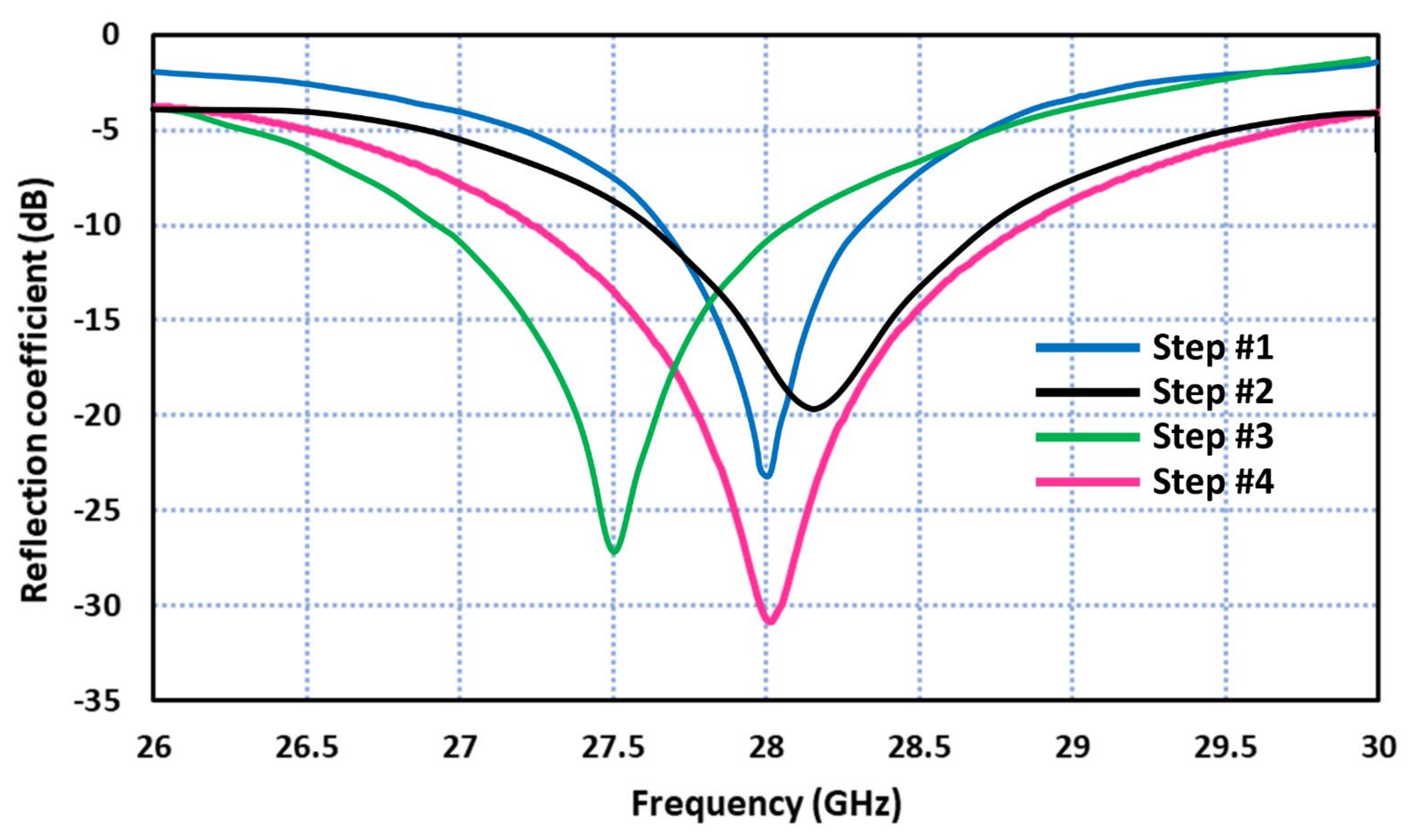
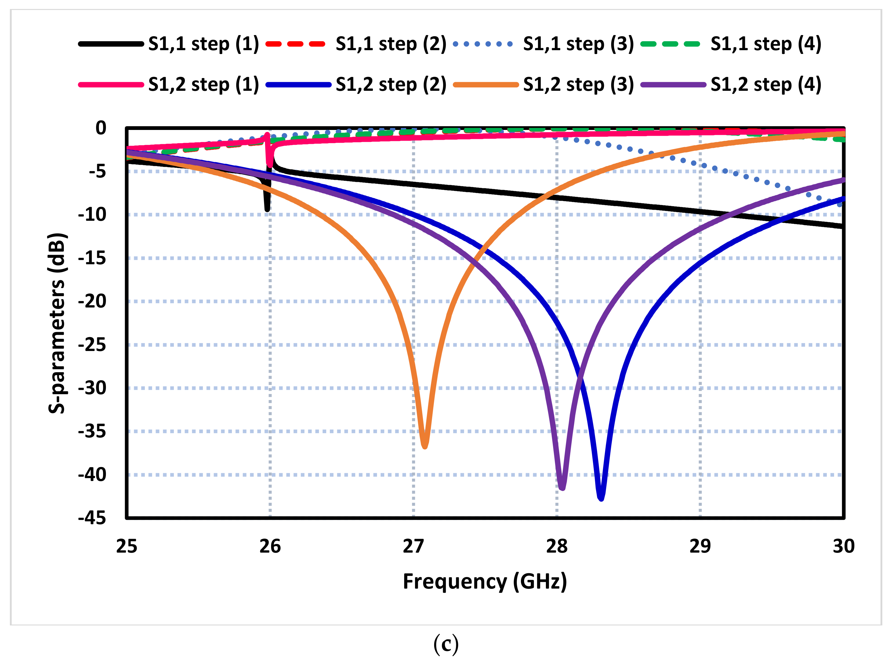
2. Antenna Design Procedure
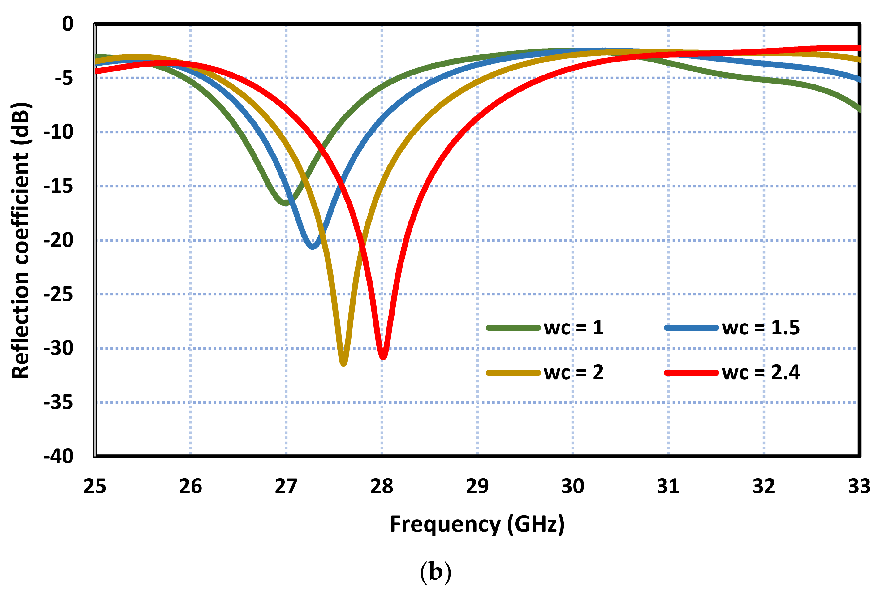
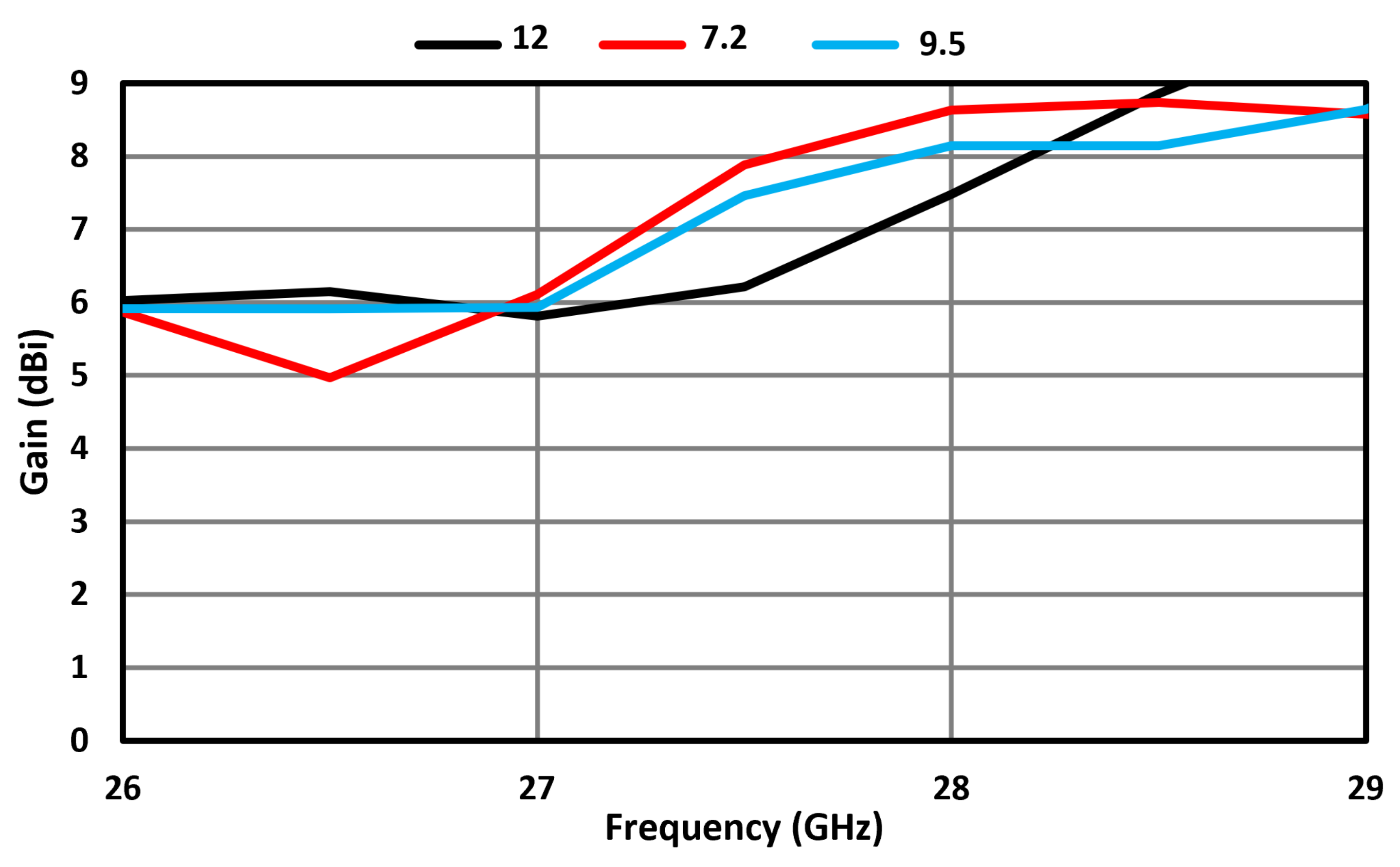
3. Effect of Ground Plane Rectangular Slot
4. MIMO Antenna Array
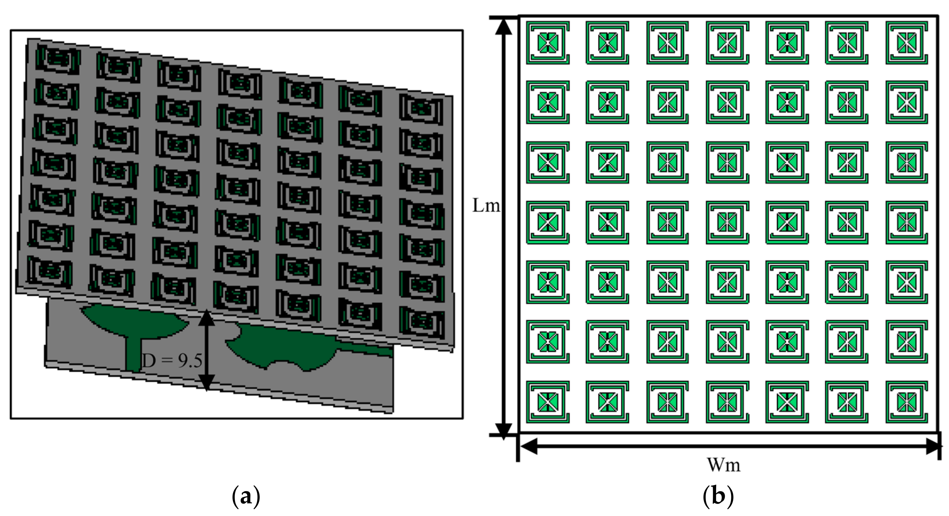
5. Frequency-Selective Surface Unit Cell
6. FSS-Loaded Antenna
7. Measured Results
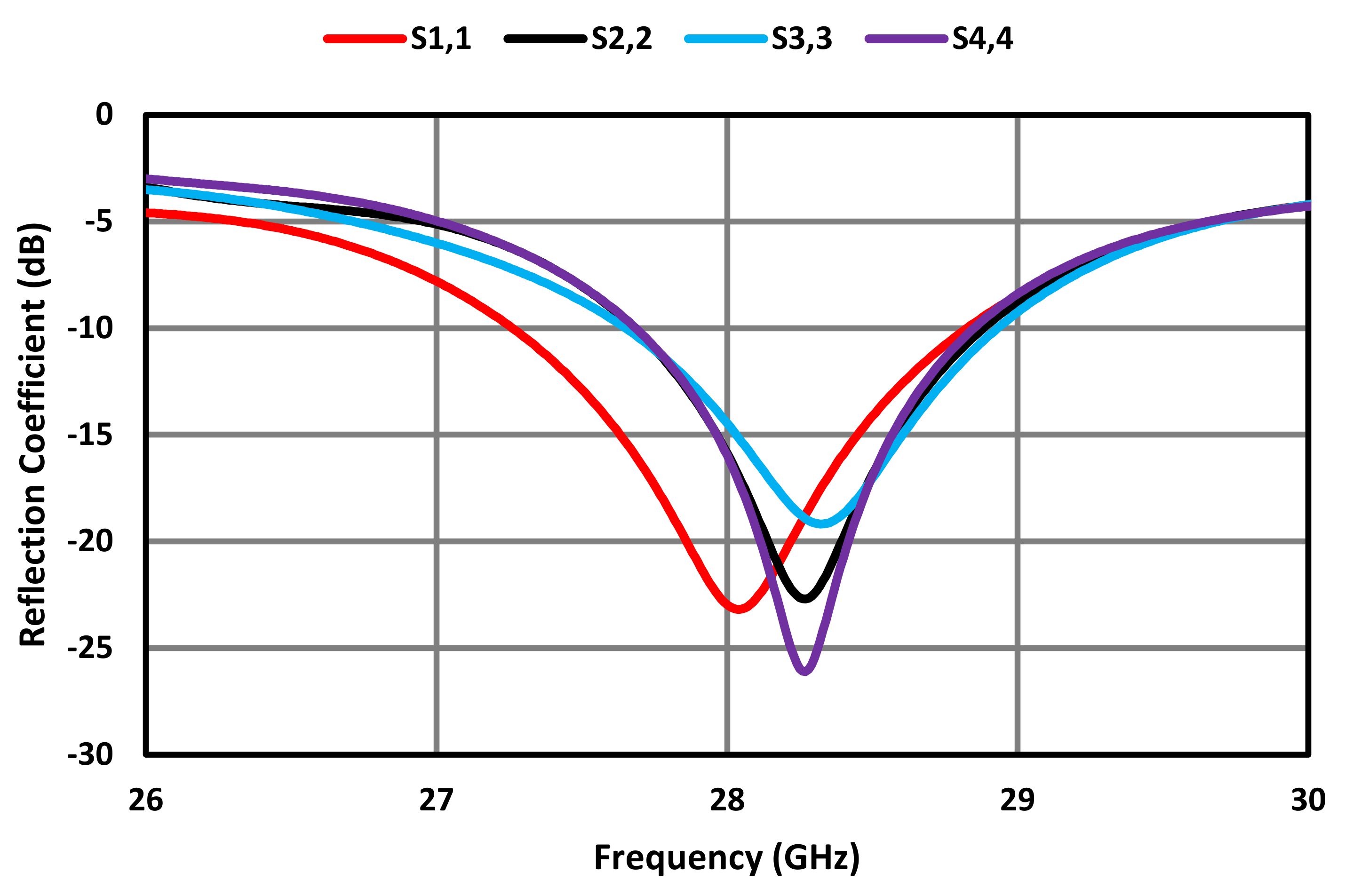
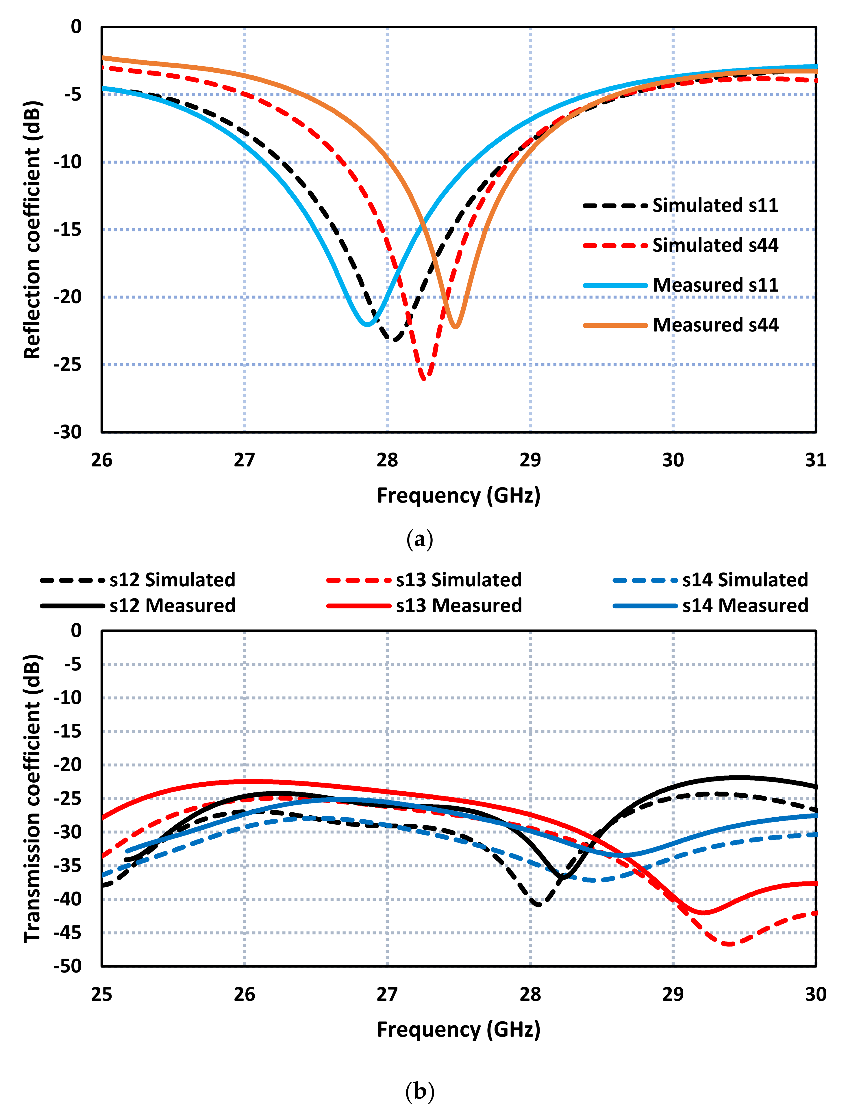
7.1. S-Parameters
7.2. 2D Radiation Patterns
8. MIMO Performance Parameters
8.1. Envelope Correlation Coefficient
8.2. Diversity Gain
9. Conclusions
Author Contributions
Funding
Institutional Review Board Statement
Informed Consent Statement
Data Availability Statement
Acknowledgments
Conflicts of Interest
References
- Abirami, M. A review of patch antenna design for 5G. In Proceedings of the 2017 IEEE International Conference on Electrical, Instrumentation and Communication Engineering (ICEICE), Karur, India, 27–28 April 2017; pp. 1–3. [Google Scholar]
- Tariq, S.; Naqvi, S.I.; Hussain, N.; Amin, Y. A metasurface-based MIMO antenna for 5G millimeter-wave applications. IEEE Access 2021, 9, 51805–51817. [Google Scholar] [CrossRef]
- Mohamed, H.A.; Edries, M.; Abdelghany, M.A.; Ibrahim, A.A. Millimeter-wave antenna with gain improvement utilizing reflection FSS for 5G networks. IEEE Access 2022, 10, 73601–73609. [Google Scholar] [CrossRef]
- Jeong, M.J.; Hussain, N.; Park, J.W.; Park, S.G.; Rhee, S.Y.; Kim, N. Millimeter-wave microstrip patch antenna using vertically coupled split ring metaplate for gain enhancement. Microw. Opt. Technol. Lett. 2019, 61, 2360–2365. [Google Scholar] [CrossRef]
- Przesmycki, R.; Bugaj, M.; Nowosielski, L. Broadband microstrip antenna for 5G wireless systems operating at 28 GHz. Electronics 2020, 10, 1. [Google Scholar] [CrossRef]
- Kim, G.; Kim, S. Design and Analysis of dual polarized broadband microstrip patch antenna for 5G mmWave antenna module on FR4 substrate. IEEE Access 2021, 9, 64306–64316. [Google Scholar] [CrossRef]
- Abdelaziz, A.; Mohamed, H.A.; Hamad, E.K.I. Applying characteristic mode analysis to systematically design of 5G logarithmic spiral MIMO patch antenna. IEEE Access 2021, 9, 156566–156580. [Google Scholar] [CrossRef]
- Zahra, H.; Awan, W.A.; Ali, W.A.E.; Hussain, N.; Abbas, S.M.; Mukhopadhyay, S. A 28 GHz broadband helical inspired end-fire antenna and its MIMO configuration for 5G pattern diversity applications. Electronics 2021, 10, 405. [Google Scholar] [CrossRef]
- Hussain, N.; Awan, W.A.; Ali, W.; Naqvi, S.I.; Zaidi, A.; Le, T.T. Compact wideband patch antenna and its MIMO configuration for 28 GHz applications. AEU Int. J. Electron. Commun. 2021, 132, 153612. [Google Scholar] [CrossRef]
- Rahman, M.; NagshvarianJahromi, M.; Mirjavadi, S.S.; Hamouda, A.M. Compact UWB band-notched antenna with integrated Bluetooth for personal wireless communication and UWB applications. Electronics 2019, 8, 158. [Google Scholar] [CrossRef]
- Sharawi, M.S. Printed multi-band MIMO antenna systems and their performance metrics. IEEE Antennas Propag. Mag. 2013, 55, 218–232. [Google Scholar] [CrossRef]
- Ojaroudi Parchin, N.; Basherlou, H.J.; Alibakhshikenari, M.; Parchin, Y.O.; Al-Yasir, Y.I.A.; Abd-Alhameed, R.A.; Limiti, E. Mobile-phone antenna array with diamond-ring slot elements for 5G massive MIMO systems. Electronics 2019, 8, 521. [Google Scholar] [CrossRef]
- Hussain, M.; Ali, E.M.; Jarchavi, S.M.R.; Zaidi, A.; Najam, A.I.; Alotaibi, A.A.; Althobaiti, A.; Ghoneim, S.S.M. Design and characterization of compact broadband antenna and its MIMO configuration for 28 GHz 5G applications. Electronics 2022, 11, 523. [Google Scholar] [CrossRef]
- Khalid, M.; Naqvi, S.I.; Hussain, N.; Rahman, M.; Fawad; Mirjavadi, S.S.; Khan, M.J.; Amin, Y. 4-Port MIMO antenna with defected ground structure for 5G millimeter wave applications. Electronics 2020, 9, 71. [Google Scholar] [CrossRef]
- Kamal, M.M.; Yang, S.; Ren, X.-C.; Altaf, A.; Kiani, S.H.; Anjum, M.R.; Iqbal, A.; Asif, M.; Saeed, S.I. Infinity shell shaped MIMO antenna array for mm-wave 5G applications. Electronics 2021, 10, 165. [Google Scholar] [CrossRef]
- Murthy, N. Improved isolation metamaterial inspired mm-Wave MIMO dielectric resonator antenna for 5G application. Prog. Electromagn. Res. C 2020, 100, 247–261. [Google Scholar] [CrossRef]
- Khalid, H.; Khalid, M.; Fatima, A.; Khalid, N. 2 × 2 MIMO antenna with defected ground structure for mm-wave 5G applications. In Proceedings of the 13th International Conference on Mathematics, Actuarial Science, Computer Science and Statistics (MACS), Karachi, Pakistan, 14–15 December 2019; pp. 1–6. [Google Scholar]
- Din, I.U.; Ullah, S.; Mufti, N.; Ullah, R.; Kamal, B.; Ullah, R. Metamaterial-based highly isolated MIMO antenna system for 5G smartphone application. Int. J. Commun. Syst. 2023, 36, e5392. [Google Scholar] [CrossRef]
- Balanis, C.A. Handbook of Microstrip Antennas; John Wiley and Sons: New York, NY, USA, 1982. [Google Scholar]
- Munk, B.A. Frequency Selective Surfaces: Theory and Design; Wiley Online Library: Hoboken, NJ, USA, 2000; Volume 29. [Google Scholar]


| Symbol | Dimensions (mm) |
|---|---|
| Ls | 18 |
| Lg | 18 |
| Lf | 6 |
| Wf | 1.5 |
| R | 6 |
| R1 | 2 |
| Lc | 13.9 |
| Wc | 2.4 |
| Ws | 19 |
| Wg | 19 |
| Slot Length (Lc) (mm) | Slot Width (Wc) (mm) | Freq. Range (GHz) | Impedance BW (GHz) |
|---|---|---|---|
| 5 | 1 | 26.6–27.6 | 1 |
| 7 | 1.5 | 26.4–27.2 | 0.8 |
| 9.5 | 2 | 33.2–34 | 0.8 |
| 13.9 | 2.4 | 27–29 | 2 |
| Parameters | Symbols | Value (mm) |
|---|---|---|
| Substrate length and width | Ls = Ws | 3.7 |
| Gap one | g1 | 0.24 |
| Gap two | g2 | 0.25 |
| Gap three | g3 | 0.27 |
| Length of FSS | Lm | 45 |
| Width of FSS | Wm | 45 |
| Ref | f (GHz) | Ports | Dimension in (mm) | Min. Isolation (dB) | Gain (dBi) | ECC | Techniques |
|---|---|---|---|---|---|---|---|
| [9] | 28 | 2 | 30 × 15 × 0.25 | 35.8 | 5.42 | <0.005 | DGS |
| [13] | 27 | 4 | 30 × 30 × 1.575 | 30 | 7.1 | <0.005 | DGS |
| [14] | 28 | 4 | 30 × 35 × 0.76 | 17 | 8.3 | <0.010 | DGS |
| [8] | 28 | 2 | 15 × 25 × 0.203 | 30 | 5.8 | <0.005 | DGS |
| [15] | 28 | 4 | 30 × 30 × 0.787 | 29 | 6.1 | <0.160 | DGS |
| [16] | 28 | 4 | 20 × 40 × 1.6 | 29.34 | 7 | <0.010 | DRA |
| [17] | 27 | 4 | 30 × 28 × 0.508 | 24 | 6.22 | <0.050 | DGS |
| [18] | 28 | 2 | 18 × 36 × 0.8 | 64 | 8.75 | <0.050 | SRR/DGS |
| Proposed MIMO without FSS | 28 | 4 | 38 × 36 × 0.8 | 26.31 | 7.2 | <0.002 | DGS |
| Proposed MIMO with FSS | 28 | 4 | 45 × 45 × 0.8 | 23.31 | 8.6 | <0.002 | FSS/DGS |
Disclaimer/Publisher’s Note: The statements, opinions and data contained in all publications are solely those of the individual author(s) and contributor(s) and not of MDPI and/or the editor(s). MDPI and/or the editor(s) disclaim responsibility for any injury to people or property resulting from any ideas, methods, instructions or products referred to in the content. |
© 2023 by the authors. Licensee MDPI, Basel, Switzerland. This article is an open access article distributed under the terms and conditions of the Creative Commons Attribution (CC BY) license (https://creativecommons.org/licenses/by/4.0/).
Share and Cite
Ud Din, I.; Alibakhshikenari, M.; Virdee, B.S.; Jayanthi, R.K.R.; Ullah, S.; Khan, S.; See, C.H.; Golunski, L.; Koziel, S. Frequency-Selective Surface-Based MIMO Antenna Array for 5G Millimeter-Wave Applications. Sensors 2023, 23, 7009. https://doi.org/10.3390/s23157009
Ud Din I, Alibakhshikenari M, Virdee BS, Jayanthi RKR, Ullah S, Khan S, See CH, Golunski L, Koziel S. Frequency-Selective Surface-Based MIMO Antenna Array for 5G Millimeter-Wave Applications. Sensors. 2023; 23(15):7009. https://doi.org/10.3390/s23157009
Chicago/Turabian StyleUd Din, Iftikhar, Mohammad Alibakhshikenari, Bal S. Virdee, Renu Karthick Rajaguru Jayanthi, Sadiq Ullah, Salahuddin Khan, Chan Hwang See, Lukasz Golunski, and Slawomir Koziel. 2023. "Frequency-Selective Surface-Based MIMO Antenna Array for 5G Millimeter-Wave Applications" Sensors 23, no. 15: 7009. https://doi.org/10.3390/s23157009
APA StyleUd Din, I., Alibakhshikenari, M., Virdee, B. S., Jayanthi, R. K. R., Ullah, S., Khan, S., See, C. H., Golunski, L., & Koziel, S. (2023). Frequency-Selective Surface-Based MIMO Antenna Array for 5G Millimeter-Wave Applications. Sensors, 23(15), 7009. https://doi.org/10.3390/s23157009