
SIW-Based Circularly Polarized Antenna Array for 60 GHz 5G Band: Feasibility Study


Abstract
:1. Introduction
- Circular patches were replaced by spirals in [8].
- Linear apertures were replaced by crosses and elements by rotated cross-shaped patches [9].
- In [10], three additional feeding layers were used, making the fabrication highly demanding. In the paper, no information about the axial ratio was provided.
- In [11], phase shifters were used so that the circular polarization could be excited. The implementation of phase shifters increases the antenna dimensions.
2. From 17 GHz to 60 GHz
- Dimensions of coupling slots between the layers;
- Position of coupling slots between the layers;
- Width of the waveguides;
- Dimensions of the patches.
3. Results
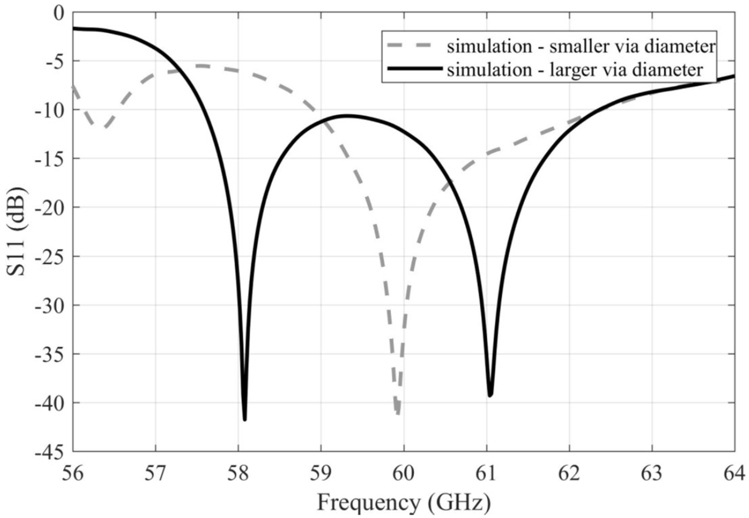
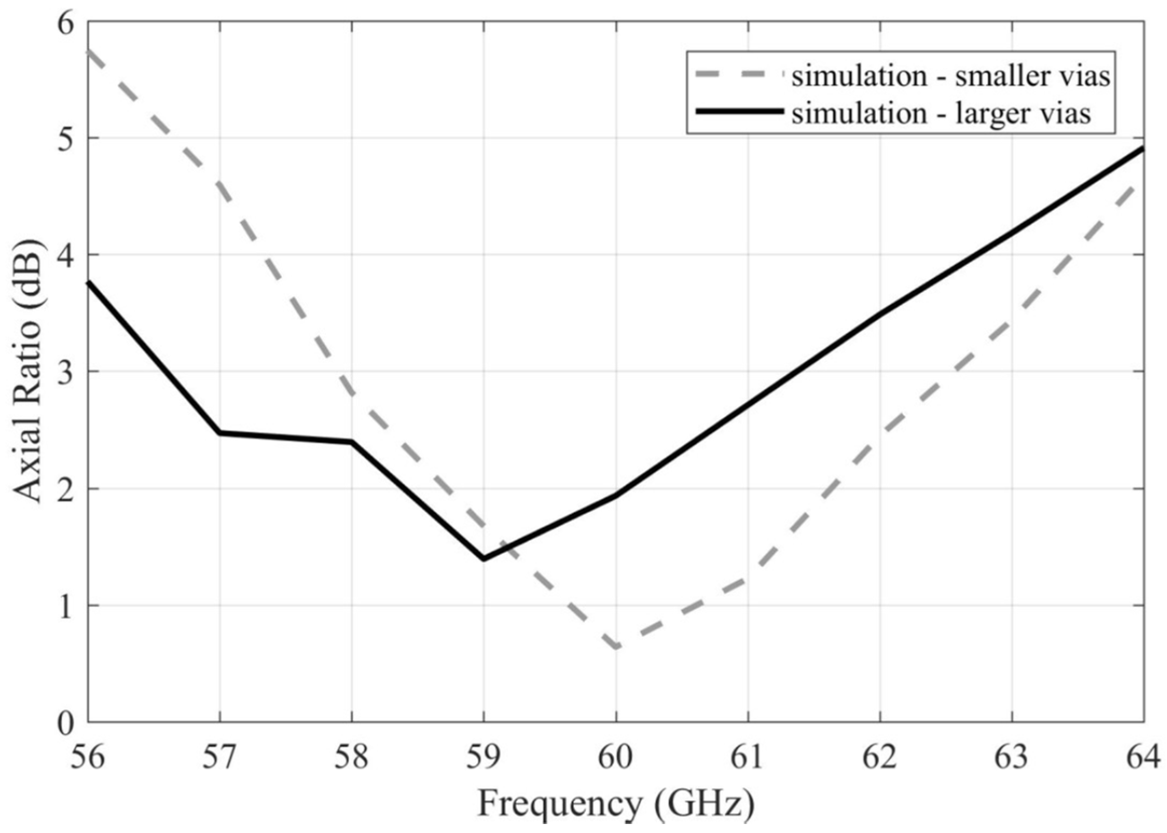
3.1. Smaller Vias
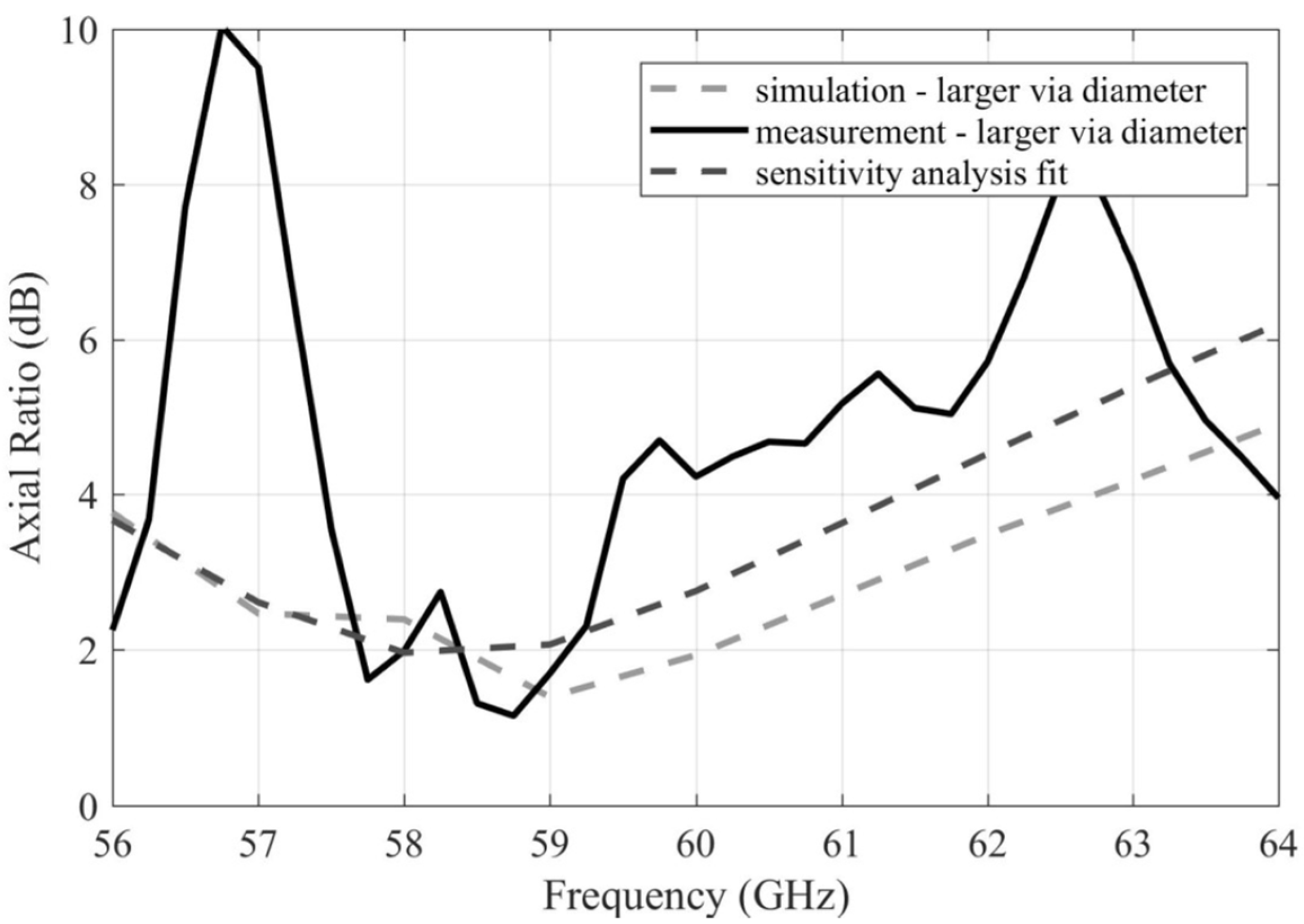
3.2. Larger Vias
3.3. Additional Patches
4. Summary
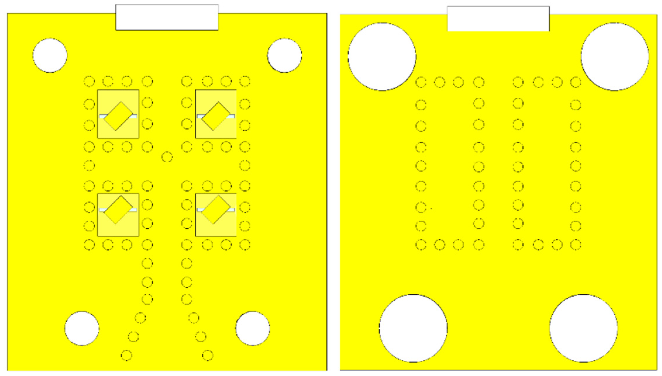
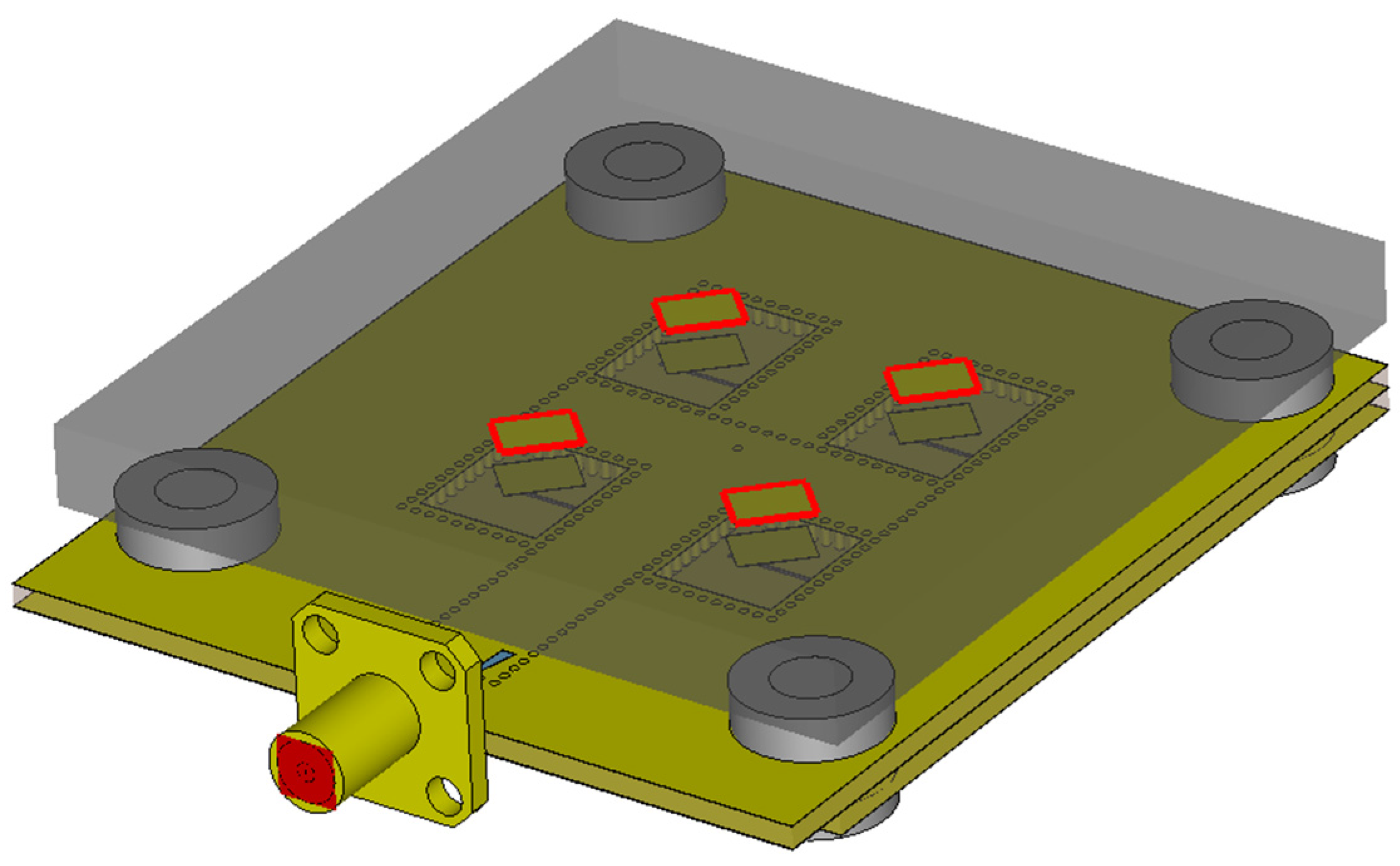
- A 2 × 2 patch array was selected as an initial structure to reach an initial gain and radiation properties. In order to allow an improvement of the gain and directive properties in the future, a modular concept was designed so that the array can be easily extended to 4 × 4, 8 × 8, etc. elements.
- Since the parasitic radiation of feeders becomes significant at 17 GHz, a substrate-integrated feeding network was designed. In the initial simulations, continuous side walls were assumed, and losses in the metallic components were neglected. The dimensions of the feeders, slots, and radiators (all related to the wavelength) were optimized.
- Continuous side walls were replaced by vias, and the numerical model was conceived to be as realistic as possible.
- Since all dimensions of the radiators and feeders are related to the wavelength, a rough redesign considered wavelength shortening when thinner substrates at 60 GHz were used. For the initial optimization, a simplified numerical model with continuous side walls was used.
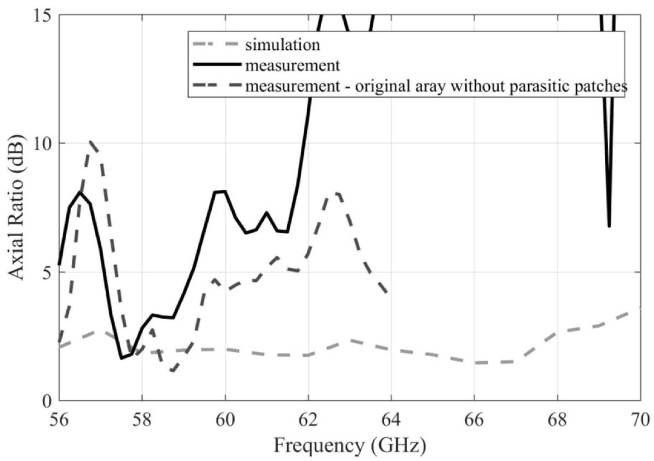
- Since the optimization of the axial ratio was not successful, a layer with parasitic patches was placed above the array. Thanks to the higher number of degrees of freedom, the subsequent optimization was successful.
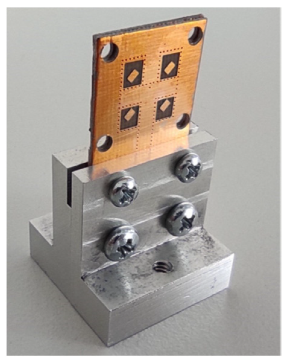
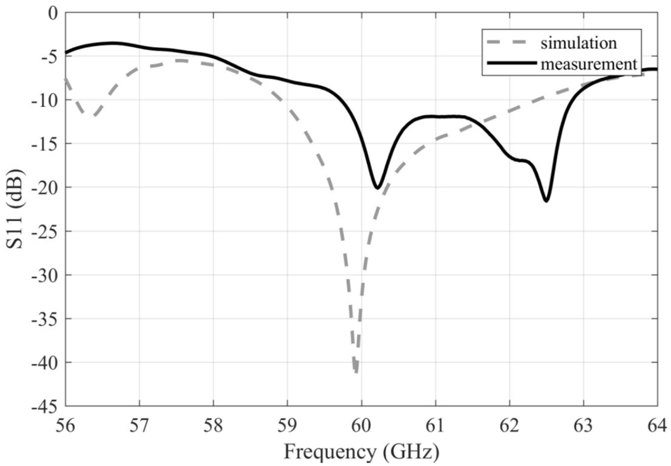
- When the realistic model was developed and the first antenna prototype was produced, problems with manufacturing tolerances were revealed. Therefore, deep sensitivity and tolerance analyses were performed. Those analyses showed that the increased radius of vias in the side walls of SIW feeders might solve the problem. A new value of radii of vias was defined by the workshop, and the design was optimized afterwards accordingly.
- The attainable manufacturing precision needs to be thoroughly considered and assessed. The sensitivity analysis indicated that a manufacturing precision with less than ±0.1 mm variance of the dimensions around the center (ideal) value is needed.
- The manufacturing of vias has to be considered as becoming generally more difficult in the case of the microwave substrates like ARLON CuClad 217 LX. Drilling such substrates, a residual material in drilled holes is left that complicates the metallization processes. This issue grows with the decreasing diameter of the vias. Hence, the diameter of the vias needs to be carefully chosen so that the acceptable manufacturing quality of the vias can be guaranteed.
- Since the width of the coupling slots between the substrates is reduced to 0.2 mm, precise alignment of the substrates is critical. It is desirable to include additional alignment points to the design in order to increase the precision.
Author Contributions
Funding
Conflicts of Interest
References
- Yilmaz, T.; Fadel, E.; Akan, O.B. Employing 60 GHz ISM band for 5G wireless communications. In Proceedings of the IEEE International Black Sea Conference on Communications and Networking (BlackSeaCom), Odessa, Ukraine, 23–30 May 2014. [Google Scholar] [CrossRef] [Green Version]
- Parker, M.C.; Koczian, G.; Quinlan, T.; Walker, S.D. High capacity communications at 24 GHz and 60 GHz for converged 5G networking. In Proceedings of the 20th European Conference on Networks and Optical Communications (NOC), London, UK, 30 June–2 July 2015. [Google Scholar] [CrossRef]
- Linge, N.; Odum, R.; Hill, S.; Von Hunerbein, S.; Sutton, A.; Townend, D. The impact of atmospheric pressure on the performance of 60 GHz point to point links within 5G networks. In Proceedings of the Loughborough Antennas & Propagation Conference (LAPC), Loughborough, UK, 12–13 November 2018. [Google Scholar] [CrossRef]
- Spurek, J.; Raida, Z. Circularly polarized modular patch antenna array fed by substrate integrated waveguide. Microw. Opt. Technol. Lett. 2018, 6, 1398–1403. [Google Scholar] [CrossRef]
- Xiao, Y.; Cheng, Y.J.; He, Z.R.; Zhao, M.H.; Fan, Y. A 60 GHz circularly polarized phased array with fan-out feedlines. In Proceedings of the International Conference on Microwave and Millimeter Wave Technology (ICMMT), Nanjing, China, 23–26 May 2021. [Google Scholar] [CrossRef]
- Al-Saedi, H.; Raeesi, A.; Wahab, W.M.A.; Gigoyan, S.; Safavi-Naeini, S. 60-GHz circularly polarized annular patch antenna fed by substrate integrated waveguide. In Proceedings of the 18th International Symposium on Antenna Technology and Applied Electromagnetics (ANTEM), Waterloo, Canada, 19–22 August 2018. [Google Scholar] [CrossRef]
- Zhu, Y.; Qi, Z.; Zhu, H.; Li, X. 60-GHz wideband circularly polarized antenna array based on TE340-mode SIC and sequential rotation feeding technique. IET Microw. Antennas Prop. 2020, 7, 807–814. [Google Scholar] [CrossRef]
- Zhu, J.; Liao, S.; Li, S.; Xue, Q. 60 GHz wideband high-gain circularly polarized antenna array with substrate integrated cavity excitation. IEEE Antennas Wirel. Prop. Lett. 2018, 5, 751–755. [Google Scholar] [CrossRef]
- Zhu, J.; Li, S.; Liao, S.; Yang, Y.; Zhu, H. 60 GHz substrate-integrated-waveguide-fed patch antenna array with quadri-polarization. IEEE Trans. Antennas Prop. 2018, 12, 7406–7411. [Google Scholar] [CrossRef]
- Zhao, Y.; Luk, K.M. Dual circular-polarized SIW-fed high-gain scalable antenna array for 60 GHz applications. IEEE Trans. Antennas Prop. 2018, 3, 1288–1298. [Google Scholar] [CrossRef]
- Zhu, J.; Liao, S.; Yang, Y.; Li, S.; Xue, Q. 60 GHz dual-circularly polarized planar aperture antenna and array. IEEE Trans. Antennas Prop. 2018, 2, 1014–1019. [Google Scholar] [CrossRef]
- Cheng, X.; Yao, Y.; Tomura, T.; Hirokawa, J.; Yu, T.; Yu, J.; Chen, X. A compact multi-beam end-fire circularly polarized septum antenna array for millimeter-wave applications. IEEE Access 2018, 6, 62784–62792. [Google Scholar] [CrossRef]
- Rogers Corporation: CuClad Series Laminates Data Sheet. Available online: https://rogerscorp.com/-/media/project/rogerscorp/documents/advanced-electronics-solutions/english/data-sheets/cuclad-laminates-data-sheet.pdf (accessed on 14 March 2022).
- Spurek, J.; Raida, Z. Sensitivity analysis of a modular circularly polarized antenna array for 60 GHz band. In Proceedings of the 23rd International Microwave and Radar Conference (MIKON), Warsaw, Poland, 5–8 October 2020. [Google Scholar] [CrossRef]
- CST Studio Suite: Electromagnetic Field Simulation Software. Available online: https://www.3ds.com/products-services/simulia/products/cst-studio-suite/ (accessed on 14 March 2022).
- Spurek, J.; Raida, Z. Extending axial ratio bandwidth of antenna array by parasitic patches. In Proceedings of the 22nd International Microwave and Radar Conference (MIKON), Poznan, Poland, 14–17 May 2018. [Google Scholar] [CrossRef]
- Spurek, J.; Raida, Z. Realization of circularly polarized antenna array with parasitic patches. In Proceedings of the IEEE-APS Topical Conference on Antennas and Propagation in Wireless Communications (APWC), Granada, Spain, 9–13 September 2019. [Google Scholar] [CrossRef]


| Symbols | Description | Value |
|---|---|---|
| L | length of the array | 21.000 mm |
| L1 | length of the SIWs in the bottom layer | 9.600 mm |
| L2 | length of the interlayer coupling slots | 2.175 mm |
| L3 | length of the patch coupling slots | 2.200 mm |
| L4 | length of the patches | 0.984 mm |
| L5 | length of the upper patch windows | 3.850 mm |
| L6 | length of the lower patch windows | 3.450 mm |
| W | width of the array | 18.732 mm |
| W1 | width of the SIWs in the bottom layer | 3.408 mm |
| W2 | width of the patch coupling slots | 0.200 mm |
| W3 | width of the interlayer coupling slots | 0.200 mm |
| W4 | width of the patches | 1.428 mm |
| W5 | width of the SIWs in the top layer | 2.316 mm |
| D1 | spacing between the SIWs in the bottom layer | 2.316 mm |
| D2 | upper distance of the SIWs in the bottom layer from the edge of the array | 4.000 mm |
| D3 | distance of the patch coupling slots from the ends of the SIWs in the bottom layer | 1.950 mm |
| D4 | spacing between the patch and interlayer coupling slots | 2.550 mm |
| D5 | offset of the interlayer coupling slots from the center of the horizontal SIW in the top layer | 0.016 mm |
| D6 | distance of the divider via from the edge of the horizontal SIW in the top layer | 0.300 mm |
| Dv | diameter of the vias | 0.600 mm |
| Ds | spacing between the vias | 1.150 mm |
| R | rotation of the patches | 45° |
| Symbols | Value (17 GHz) | Value (60 GHz) |
|---|---|---|
| L | 65.000 mm | 21.000 mm |
| L1 | 32.400 mm | 9.600 mm |
| L2 | 7.500 mm | 2.175 mm |
| L3 | 6.500 mm | 2.200 mm |
| L4 | 3.920 mm | 0.984 mm |
| L5 | 13.600 mm | 3.850 mm |
| L6 | 11.600 mm | 3.450 mm |
| W | 57.270 mm | 18.732 mm |
| W1 | 10.000 mm | 3.408 mm |
| W2 | 0.300 mm | 0.200 mm |
| W3 | 0.600 mm | 0.200 mm |
| W4 | 5.080 mm | 1.428 mm |
| W5 | 7.200 mm | 2.316 mm |
| D1 | 7.200 mm | 2.316 mm |
| D2 | 12.800 mm | 4.000 mm |
| D3 | 7.250 mm | 1.950 mm |
| D4 | 8.350 mm | 2.550 mm |
| D5 | 0.700 mm | 0.016 mm |
| D6 | 2.500 mm | 0.300 mm |
| Dv | 0.600 mm | 0.600 mm |
| Ds | 1.010 mm | 1.150 mm |
| R | 45° | 45° |
| S11 bandwidth | 4.8% | 8.5% |
| AR bandwidth | 7.1% | 2.3% |
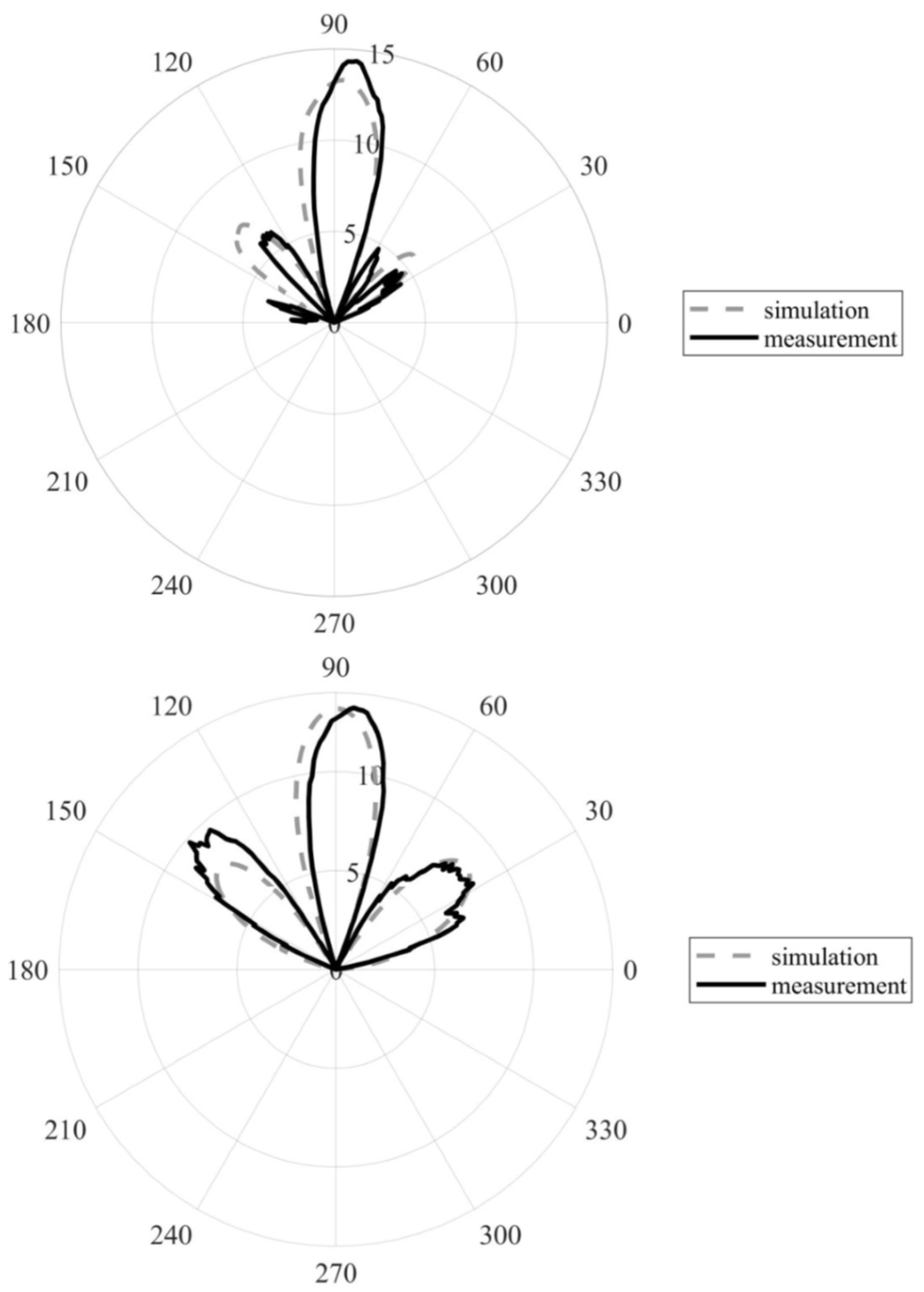
| Beamwidth (XY) | 27.1° | 20.0° |
| Beamwidth (YZ) | 30.1° | 18.0° |
| Realized gain (peak) | 12.6 dB | 14.3 dB |
Publisher’s Note: MDPI stays neutral with regard to jurisdictional claims in published maps and institutional affiliations. |
© 2022 by the authors. Licensee MDPI, Basel, Switzerland. This article is an open access article distributed under the terms and conditions of the Creative Commons Attribution (CC BY) license (https://creativecommons.org/licenses/by/4.0/).
Share and Cite
Spurek, J.; Raida, Z. SIW-Based Circularly Polarized Antenna Array for 60 GHz 5G Band: Feasibility Study. Sensors 2022, 22, 2945. https://doi.org/10.3390/s22082945
Spurek J, Raida Z. SIW-Based Circularly Polarized Antenna Array for 60 GHz 5G Band: Feasibility Study. Sensors. 2022; 22(8):2945. https://doi.org/10.3390/s22082945
Chicago/Turabian StyleSpurek, Jan, and Zbynek Raida. 2022. "SIW-Based Circularly Polarized Antenna Array for 60 GHz 5G Band: Feasibility Study" Sensors 22, no. 8: 2945. https://doi.org/10.3390/s22082945
APA StyleSpurek, J., & Raida, Z. (2022). SIW-Based Circularly Polarized Antenna Array for 60 GHz 5G Band: Feasibility Study. Sensors, 22(8), 2945. https://doi.org/10.3390/s22082945