Abstract
Currently, the location recognition and positioning system are the essential parts of unmanned vehicles. Among them, location estimation under GPS-denied environments is currently being studied using IMU, Wi-Fi, and VLC, but there are problems such as cumulative errors, hardware complexity, and precision positioning. To address this problem with the current positioning system, the present study proposed a lane positioning technique by analyzing the chromaticity coordinates, judging from the color temperature of LED lights in tunnels. The tunnel environment was built using LEDs with three color temperatures, and to solve nonlinear problems such as lane positioning from chromaticity analysis, a single input single output fuzzy algorithm was developed to estimate the position of an object on lanes using chromaticity values of signals measured by RGB sensors. The RGB value measured by the sensor removes the disturbance through the pre-processing filter, accepts only the tunnel LED information, and estimates where it is located on the x-distance indicating the lane position through a fuzzy algorithm. Finally, the performance of the fuzzy algorithm was evaluated through experiments, and the accuracy was shown with an average error of less than 4.86%.
1. Introduction
With the advancement of electric vehicles, autonomous vehicles are being studied in several papers for the convenience and safety of users. Cameras, communication, sensors, and controllers are combined in an existing car, and it is reflected in vehicle operation through recognition of the vehicle’s surroundings and the driver’s condition. As the driver’s intervention is reduced, the vehicle’s positioning system has become an essential element of autonomous driving [1,2,3,4,5,6,7,8]. Currently, the real-time positioning system for vehicles is highly dependent on GPS. However, since the signal strength is low, the efficiency is lowered in environments where GPS is rejected, such as blockages by buildings or structures and non-signal areas. Research using IMU, Wi-Fi, VLC, camera, for example, is in progress to supplement the accuracy problem of GPS [9,10,11]. Nevertheless, in the case of IMU, there is a problem with error generation according to time. When estimating the location using Wi-Fi, triangulation is used, but accuracy problems may occur due to magnetic field or sensor deviation, and an additional terminal is required. Visible light communication (VLC) attracts attention as an indoor positioning system. Compared to the problems of system instability and response time of other positioning methods using communication, VLC is stable against electromagnetic interference, so that it can be a good alternative [12]. There are various measurement methods and a unique ID is given to each LED. When using proximity, it is simple but has low accuracy, and when using methods such as signal strength or fingerprinting, the accuracy is high but complicated [12,13,14]. To improve the accuracy of the real-time positioning system for vehicles, the present study attempted to analyze the chromaticity of LED light and proposed a lane positioning technology for a tunnel. LED has the advantage of being small in size, having a long lifespan, and low power consumption compared to existing lights, so it is thought to replace many other lights. By estimating the chromaticity value according to the position, it is possible to estimate the position intuitively. It is expected that location estimation will be possible using the existing tunnel lighting infrastructure without the complex formulas and hardware infrastructure required for existing triangulation and Wi-Fi communication techniques.
In the current study, the positions of vehicles on lanes running inside a tunnel have been determined based only on the chromaticity of LED lights installed under the ceiling inside a simulator that imitates a tunnel environment. To that end, a fuzzy algorithm for analyzing the signals measured by RGB sensors was developed, and its performance was evaluated based on the experiment results. Fuzzy logic can solve nonlinear problems such as lane positioning from chromaticity analysis. The fuzzy algorithm showed excellent distinction ability in lane positioning using the output signals of an RGB sensor [1,2,3,4]. In this paper, Section 2, “Chromaticity of light” explains the Chromaticity with tristimulus values XYZ. Section 3, “System Principle” introduces “Construction of tunnel simulator” and “RGB sensor signal processing method”. Section 3.1 describes the measurement environment, and Section 3.2 explains the methods to remove disturbance for the RGB sensor. Section 4, “Experiment and Analysis” introduces “Fuzzy logic system design” and “Experimental results.” Section 4.1 describes the design of a Fuzzy system based on the chromaticity values collected. In Section 4.2, the result of the experiment is mentioned. Finally, Section 5, “Conclusions," discusses the analysis of the results and conclusion about the positioning system with color temperatures.
2. Chromaticity of Light
The wavelengths of the red (R), green (G), and blue (B) colors of the original stimulus are λ_R = 700.0 nm, λ_R = 546.1 nm, λ_R = 435.8 nm [1,2,3,15], respectively. The XYZ colorimetry for tristimulus values of objects is a three-color colorimetry defined by the International Commission on Illumination (CIE) for sensitivity values that are equivalent to the human eye. In the present study, the table color system with tristimulus values XYZ can be obtained through (1) using RGB values read through RGB sensors, which play the same function as the cone cells in the human eye [1,2,3,4,16].
To geometrically express the vector components of the tristimulus values XYZ, a three-dimensional color space is required, but it is inconvenient to express it. Therefore, in the XYZ color space, the intersection x, y between a unit plane X + Y + Z = 1 and the color vector (X, Y, Z) can be expressed as a two-dimensional plane using the following Equation (2) [1,2,3,15].
Once the chromaticity coordinate x, y of the chromaticity diagram, which is a two-dimensional plane, is determined, it can be used conveniently. Furthermore, a spectrum locus was drawn by connecting the chromaticity coordinates of the monochromatic lights, as shown in Figure 1.
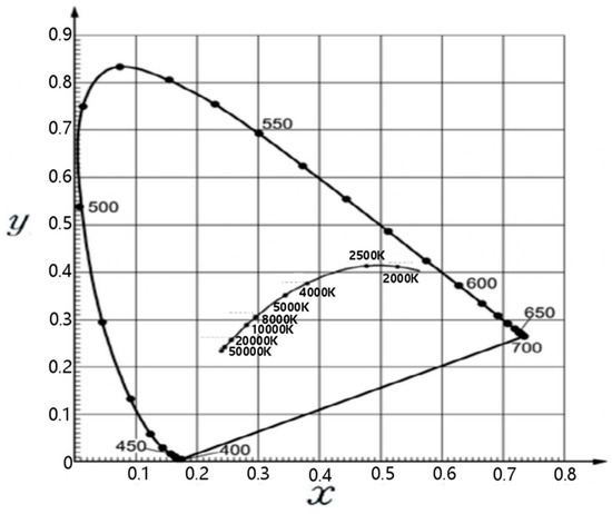
Figure 1.
2-dimensional chromaticity diagram.
A blackbody is an object that emits different colors of light corresponding to its temperature. A line that connects the chromaticity points of blackbody radiation is a blackbody locus, the small locus inside the large spectrum locus, shown in Figure 1. The blackbody locus shows x and y coordinates corresponding to the color temperature (K). The black dots on the outer trajectory mean the nm wavelength of light. In this study, the LED is assumed as a blackbody. To take advantage of the color temperature characteristics of light, warm, warm white, and white LEDs were used to have different color temperatures. Three different LEDs with color temperatures of 3000 K, 4500 K, and 6000 K are used to be measured different chromaticity values corresponding to the position of the sensor, as shown in Figure 2 and Figure 3 [1,2,3,4]. In this study, x-chromaticity was used to estimate the x-distance. The reason is that among the changes in x and y between 3000 K and 6000 K in Figure 1. the 2-dimensional chromaticity diagram, x has a wider range of change than y. Therefore, it can be estimated more sensitively to x-distance changes [1,2,3,4].
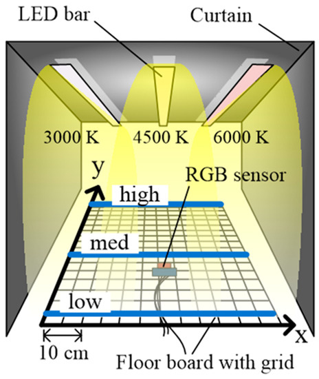
Figure 2.
Experimental environment (tunnel simulator).
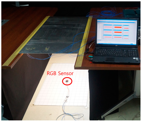
Figure 3.
Tunnel Test-bed environment.
3. System Principle
3.1. Construction of Tunnel Simulator
In this study, a tunnel environment simulator was built to validate the proposed positioning technique (see Figure 2). The simulator contained LED bars with the chromaticity of 3000 K, 4500 K, and 6000 K to illuminate a floorboard containing an x-axis (60 cm) and y-axis (80 cm). The interval between the LED bars was approximately 20 cm, and they were suspended at the height of 73 cm above the floorboard. The size of the square cells marked by grids on the floorboard was 5 cm × 5 cm and the chromaticity values were measured in each cell. After the LED lights were switched on, different chromaticity values were measured at each measurement site using the mixed lights of 3000 K, 4500 K, and 6000 K LEDs [1,2,3,4].
As shown in Figure 4, the entire system configuration sends the RGB signal input to the RGB sensor to Half-Wave Rectification & Amplifier. It proceeds with anti-distortion and amplification due to different light. In the Micro-AutoBox, a bandpass filter for removing different light signals for positioning is passed to derive chromaticity values and lateral position values through Arduino 2560&Matlab [1,2,3,4].
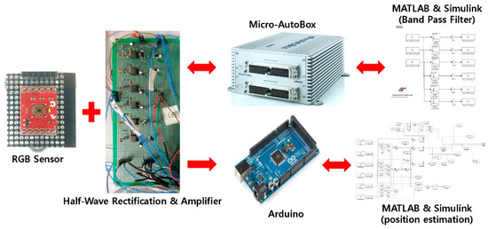
Figure 4.
Positioning system configuration plot.
3.2. RGB Sensor Signal Processing Method
The RGB sensor (HDJD-s822) used in the experiment output analog voltage values. Therefore, it also reacted to other lights from the surrounding traffic roads, in addition to the LED lights for lane positioning. To solve this problem, the RGB stimulus values of the RGB sensor from LED lights for lane positioning were separated from the other lights present in the experimental environment. The LED lights for lane positioning and the other lights were distinguished by accelerating the change over time of the former in contrast to that of the latter, which changed very slowly over time [1,2,3,4].
To apply this change of light over time, pulse-width modulation (PWM) of 1.75 kHz and 50% duty was applied by the LED switching driver. Figure 5 shows measured RGB sensor signals during signal processing. Figure 5a shows an output signal of the RGB sensor without external disturbances. It is different from those of external lights, such as those of car headlights and various road signboards. When the external light was irradiated together with the LED light for lane positioning, it showed distortion in the waveform by the frequency component of the disturbance and the floating component by the DC component of the disturbance. Figure 5b shows an output waveform of the RGB sensor when external disturbances are given. The floating components by the DC component of general light can be removed by using a capacitor. From the test, the floating component was removed by using a ceramic condenser (capacity: 0.0005 μF). The RGB stimulus values input to the RGB sensor passed through the preprocess circuit to remove the floating components and negative half of the signals before they are transferred to the Micro-AutoBox (ds1401), as shown in Figure 5c. To remove the frequency components of disturbances, digital filters are applied. An infinite impulse response (IIR) bandpass filter, which has fewer delay factors, is used. The bandpass filter is designed by using the MATLAB FDA tool and Simulink to pass the 1.75 kHz component. The Simulink model of this filter is interconnected with the Micro-AutoBox, and the performance of the filter is monitored in real-time. Figure 5d shows an output signal measured after filtering. Next, the output signal of the filter was converted to DC signal by using capacitors and inputs of the Arduino2560 (MCU). The calculation of x-chromaticity value and lane position using the fuzzy algorithm is also conducted by the Simulink model connected to Arduino2560 through the Embedded coder toolbox in MATLAB [1,2,3,4].
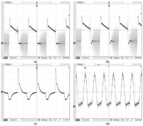
Figure 5.
Measured RGB sensor signals during signal processing [1]. (a) the output signal of the RGB sensor without external disturbances. (b) the output signal of the RGB sensor with external disturbances. (c) the output signal is measured after pre-processing circuit. (d) the output signal is measured after the bandpass filter.
4. Experiment and Analysis
4.1. Fuzzy Logic System Design
The reference chromaticity data were required to be collected before the fuzzy controller was designed. For chromaticity measurement, the chromaticity values on three lines, low, mid, and high in Figure 2, were measured corresponding to the same x-distance value on the floor coordinates. The x-distance value was increased at 10 cm intervals until it reached 60 cm and the corresponding three chromaticity values on the three lines were continuously measured. The mean value of the three chromaticity data corresponding to each x distance value was calculated and listed in Table 1. The lane positioning was conducted corresponding to the chromaticity value by using a fuzzy system designed based on the chromaticity values in Table 1.

Table 1.
Measured x-chromaticity values.
For the input of the designed single input single output (SIOS) Fuzzy system, the x-chromaticity value was defined as the input variable and the lane position, the x-distance (cm), was defined as the output. The fuzzy system, consisting of fuzzification, rule evaluation, and defuzzification procedures, was designed based on the experimental data in Table 1. Figure 6a shows the input membership function of the x-chromaticity value, which is an input variable. A triangular membership function was used in this fuzzy system. In the fuzzification procedure, x-chromaticity values were classified using the input membership function. During the procedure, the weights of the x-chromaticity values were between 0 and 1 in the triangular functions from fin1 to fin7. The rule evaluation procedure consisted of ‘if ~ then’ rule statements. This study used seven fuzzy rules (Figure 6c), which give output position values from the fuzzification procedure. To note, the rules which only have non-zero weights were activated. In the defuzzification process, the lane position was calculated from the outputs generated during the rule evaluation process. Furthermore, the weighted average technique defined by Equation (3) was used where ‘i’ is the number of activated rules, ‘M’ is the weight generated in the fuzzification procedure, and ‘W’ is the center values (0, 10, 20, …, 60) of triangle functions, in the output membership functions in Figure 6b, which was selected in the rule evaluation procedure [3].
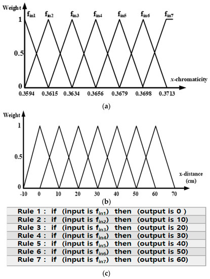
Figure 6.
Fuzzy System. (a) Input membership function. (b) Output membership function. (c) 7 Fuzzy rules.
4.2. Experimental Results
The designed fuzzy system was added to the Simulink model for lane positioning and interconnected with Arduino2560 (MCU).
Figure 7 shows the overall system diagram of this study. When the LED component with the frequency component is input to the RGB sensor, x-chromaticity is calculated through the filter unit, and the x-distance is estimated through the fuzzy system using this value.
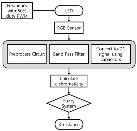
Figure 7.
System diagram of Positioning of Autonomous Vehicles.
As shown in Figure 4. To estimate the lane position corresponding to the x-chromaticity, the RGB sensor was moved by 5 cm units from 5 to 60 cm along the x-axis and 5 to 80 cm along the y-axis on the floor shown in Figure 2. The measurement results are listed in Table 2. Furthermore, to analyze the lane positioning error, the percentile errors of positioning were calculated in terms of x-distance (cm). The maximum error occurred when the x-distance was 5 cm, and the mean error was about 22.8%. The minimum error occurred when the x-distance was 60 cm, with a mean error of about 1.4%. When the errors of the first lane were excluded, the mean error was smaller than 4.86% (0.5 cm), which is smaller than the errors reported in other positioning studies [1,2,3]. Figure 8 shows the error distribution of the data. The average error rate is about 4.86%, and the almost data distribution falls within 10%, especially 0–5%, and most of the large errors occurred around 5 cm of the x-distance.
Table 2.
Experimental results of lane positioning.
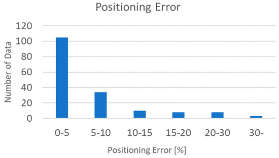
Figure 8.
Number of data per error.
5. Conclusions
In conclusion, the RGB stimulus values of LED lights were analyzed and a lane positioning system for autonomous vehicles was developed. The newly developed positioning system was also verified through experimental studies. LED lamps with three color temperatures of 3000 K, 4500 K, and 6000 K were used. The color temperatures of the lamps were mixed and overlapped, which changed the chromaticity. These changes in chromaticity were used, and the position was measured using the x-chromaticity value, which showed a larger change than the y-chromaticity value. To receive a signal differentiated from other disturbances, a specific frequency is applied to drive the LED, and as a result of the experiment using the fuzzy system, it was shown that the proposed positioning system could recognize the position well with an error level of less than 4.86% on average. It is expected that the precision of the lane positioning system under GPS-denied environments can be improved if the proposed lane positioning technology based on the chromaticity of LED street lamps is fused with the existing GPS, vision, and IMU techniques through continuous research. Besides lane positioning, two-dimensional plane positioning is also possible by arranging the LED street lamps proposed in this study under GPS-denied environments, such as inside a tunnel. Therefore, the proposed system is expected to be applicable when it is difficult to recognize lanes due to the presence of GPS interference points.
Author Contributions
Conceptualization, J.-H.J. and J.W.; methodology, J.-H.J., S.-H.J. and J.W.; software, J.-H.J. and J.W.; validation, J.-H.J. and Y.-M.J.; formal analysis, S.-G.J., Y.-M.J., S.-H.J. and J.W.; investigation, S.-H.J.; data curation, S.-H.J. and J.W.; writing original draft preparation, S.-H.J.; writing—review and editing, S.-Y.K., S.-H.J. and J.W.; visualization, J.-H.S., S.-H.J. and J.W.; supervision, J.-H.S., G.-S.B., J.-H.J. and S.-Y.K.; project administration, S.-G.J., G.-S.B. and J.-H.J. All authors have read and agreed to the published version of the manuscript.
Funding
This work was supported by a Research Grant of Pukyong National University (2021).
Institutional Review Board Statement
Not applicable.
Informed Consent Statement
Not applicable.
Data Availability Statement
Not applicable.
Conflicts of Interest
The authors declare no conflict of interest.
References
- Jeong, J.H.; Lee, D.H.; Byun, G.S.; Cho, H.R.; Cho, Y.H. The Tunnel Lane Positioning System of an Autonomous Vehicle in the LED Lighting. J. Korean Inst. Intel. Transp. Syst. 2017, 16, 186–195. [Google Scholar] [CrossRef]
- Jeong, J.H.; Kim, M.; Byun, G.S. Position Recognition for an Autonomous Vehicle Based on Vehicle-to-Led Infrastructure. In AETA 2016: Recent Advances in Electrical Engineering and Related Sciences; Lecture Notes in Electrical Engineering; Springer: Busan, Korea, 2017; pp. 913–921. [Google Scholar]
- Jeong, J.-H.; Byun, G.-S.; Park, K. Tunnel lane-positioning system for autonomous driving cars using LED chromaticity and fuzzy logic system. ETRI J. 2019, 41, 506–514. [Google Scholar] [CrossRef]
- Jeong, J.-H.; Park, K. Numerical Analysis of 2-D Positioned, Indoor, Fuzzy-Logic, Autonomous Navigation System Based on Chromaticity and Frequency-Component Analysis of LED Light. Sensors 2021, 21, 4345. [Google Scholar] [CrossRef] [PubMed]
- Kong, S.H.; Jeong, G.S. GPS/GNSS based Vehicular Positioning and Navigation Techniques. Int. J. Automot. Technol. 2015, 37, 24–28. [Google Scholar]
- Kong, S.H.; Jeon, S.Y.; Ko, H.W. Status and Trends in The Sensor Fusion Positioning Technology. J. Korean Inst. Commun. Sci. 2015, 32, 45–53. [Google Scholar]
- Lee, J.K. Automatic Driving Cars Developments Trends and Implications. Korean Inst. Electr. Eng. 2015, 64, 24–28. [Google Scholar]
- Yao, Z.; Jiang, H.; Cheng, Y.; Jiang, Y.; Ran, B. Integrated Schedule and Trajectory Optimization for Connected Automated Vehicles in a Conflict Zone. IEEE Trans. Intel. Transp. Syst. 2022, 23, 1841–1851. [Google Scholar] [CrossRef]
- Yun, D.S.; Yu, H.S. Development of the Optimized Autonomous Navigation Algorithm for the Unmanned Vehicle Using Extended Kalman Filter. Korean Soc. Automot. Eng. 2008, 16, 7–14. [Google Scholar]
- Chung, B.M.; Seok, J.W.; Cho, C.S.; Lee, J.W. Autonomous Tracking Control of Intelligent Vehicle Using GPS Information. J. Korean Soc. Precis. Eng. 2008, 25, 58–66. [Google Scholar]
- Zhu, H.; Yuen, K.-V.; Mihaylova, L.; Leung, H. Overview of Environment Perception for Intelligent Vehicles. IEEE Trans. Intel. Transp. Syst. 2017, 18, 2584–2601. [Google Scholar] [CrossRef] [Green Version]
- Rahman, M.S.; Haque, M.M.; Kim, K.-D. Indoor positioning by LED visible light communication and image sensors. Int. J. Electr. Comput. Eng. 2011, 1, 161–170. [Google Scholar] [CrossRef]
- Del Campo-Jimenez, G.; Perandones, J.M.; Lopez-Hernandez, F.J. A VLC-based beacon location system for mobile applications. In Proceedings of the 2013 International Conference on Localization and GNSS (ICL-GNSS), Turin, Italy, 1–4 June 2013. [Google Scholar]
- Fang, J.; Zhen, Y.; Shun, L.; Wu, Z.; Zhao, X.; Liang, F.; Jiang, Z.L.; Chen, Z. High-speed indoor navigation system based on visible light and mobile phone. IEEE Photon. J. 2017, 9, 1–11. [Google Scholar] [CrossRef]
- Wang, J.; Schroedl, S.; Mezger, K.; Ortloff, R.; Joos, A.; Passegger, T. Lane Keeping Based on Location Technology. IEEE Trans. Intel. Transp. Syst. 2005, 6, 351–356. [Google Scholar] [CrossRef]
- Noboru, O. Introduction to Color Reproduction Technology; JINSEM MEDIA: Seoul, Korea, 2011; pp. 9–25. [Google Scholar]
Publisher’s Note: MDPI stays neutral with regard to jurisdictional claims in published maps and institutional affiliations. |
© 2022 by the authors. Licensee MDPI, Basel, Switzerland. This article is an open access article distributed under the terms and conditions of the Creative Commons Attribution (CC BY) license (https://creativecommons.org/licenses/by/4.0/).