An Image Augmentation Method Based on Limited Samples for Object Tracking Based on Mobile Platform


Abstract
:
1. Introduction
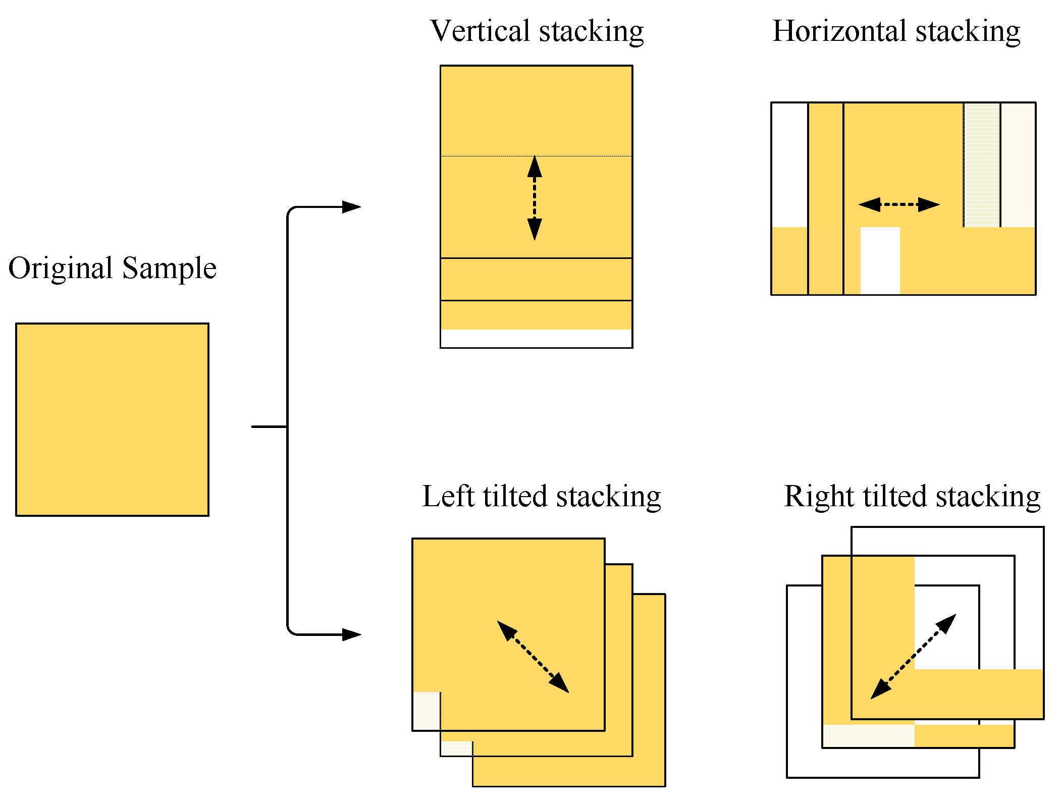
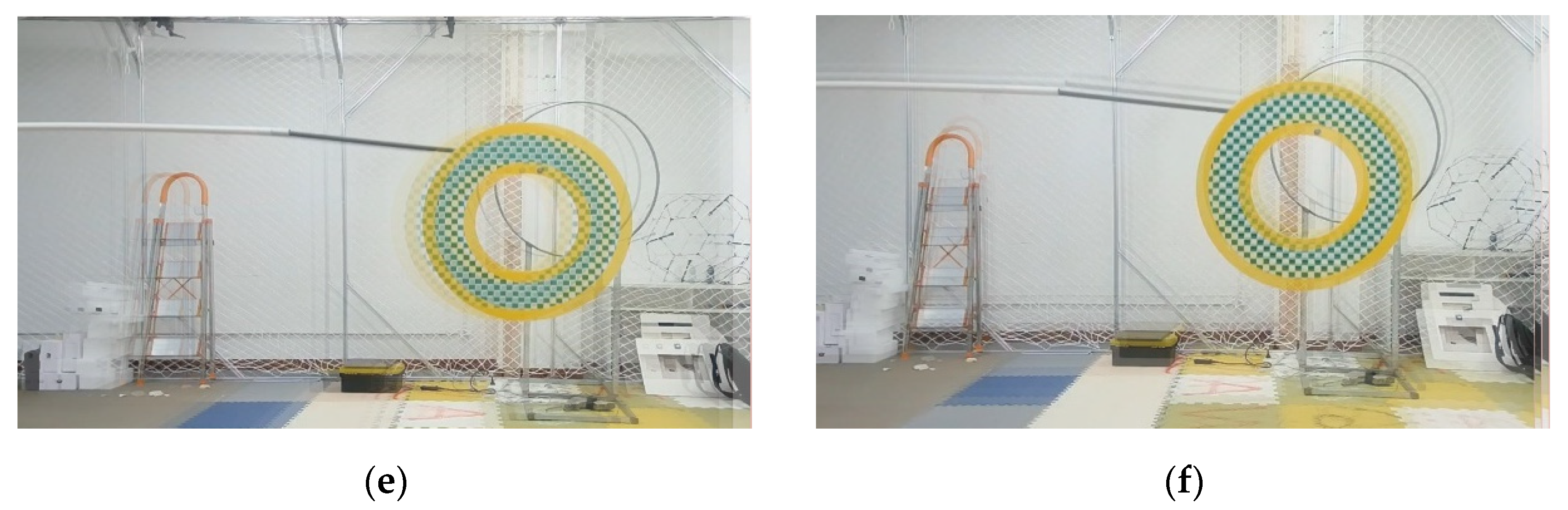
- A multi-directional stacking blur augmentation method is proposed to deal with the imaging blur problem caused by the platform shaking and the fast-moving object in the scene of a mobile platform. Experiments show that the blur augmentation method can effectively improve the recognition accuracy of the test set with imaging blur characteristics. A random background padding method is proposed to deal with the missing images such as black borders and black blocks in the augmented area due to geometric transformation. Experiments show that the background padding method can improve the recognition accuracy of the neural-network-based detection model to a certain extent.
- Based on the two augmentation methods in part 1, combined with traditional augmentation methods such as geometric augmentation, brightness adjustment, Gaussian noise injection, and color jittering, an image augmentation model is proposed to deal with the problem of object tracking in insufficient samples. Experiments show that the model can effectively improve the tracking accuracy of random moving objects in three-dimensional space.
- Combined with the author’s previous research work on object tracking [19,20], the object localization and tracking framework with image augmentation for limited samples is proposed. This framework can effectively deal with the problem of object loss caused by space rotation, platform jitter, and fast movement of the object in the 3D tracking. Besides, we use multiple open-source datasets for testing, which verifies the reliability and stability of the algorithm proposed in this paper.
2. Related Works
2.1. Datasets for Tracking
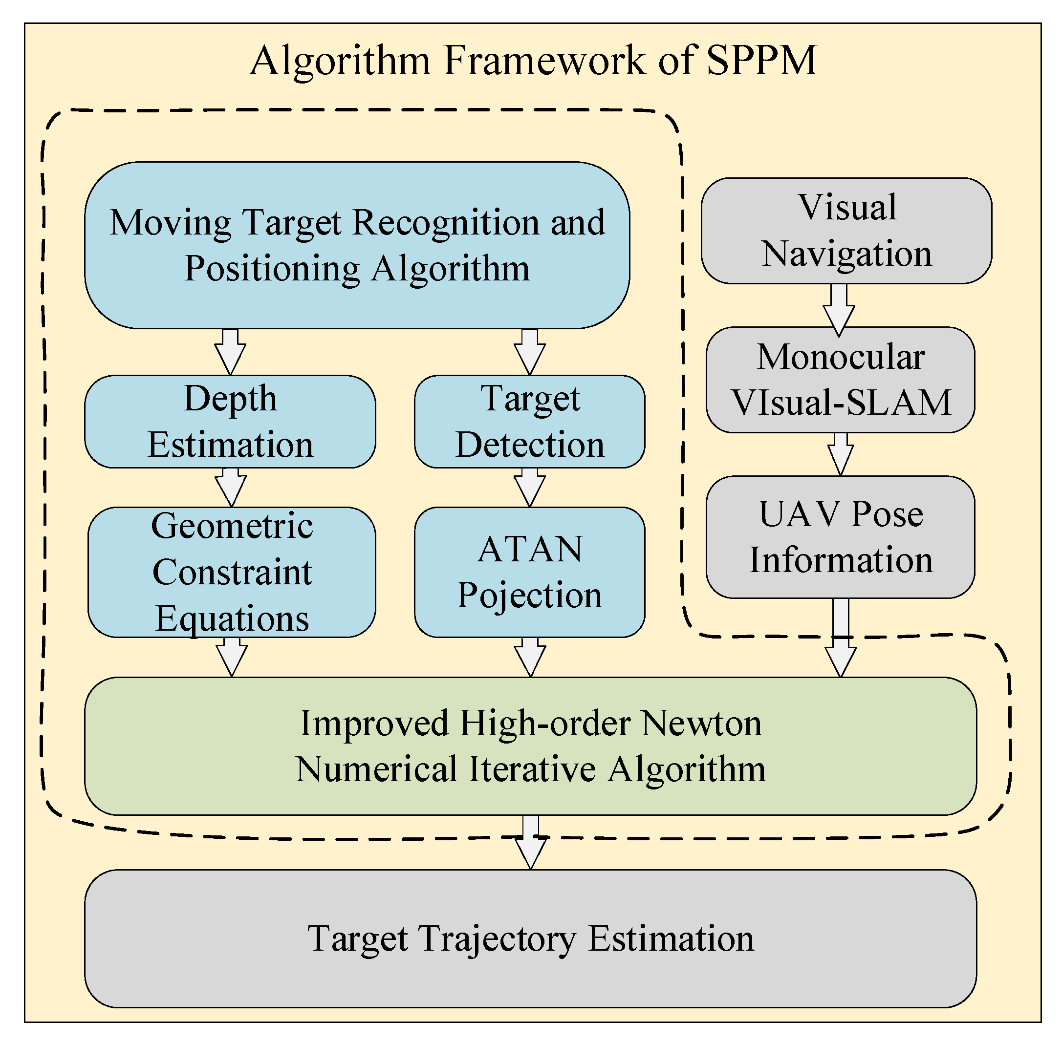
2.2. SPPM for 3D Positioning Method
2.3. Detection Model and Augmentation Methods
3. Image Augmentation Based on Limited Samples
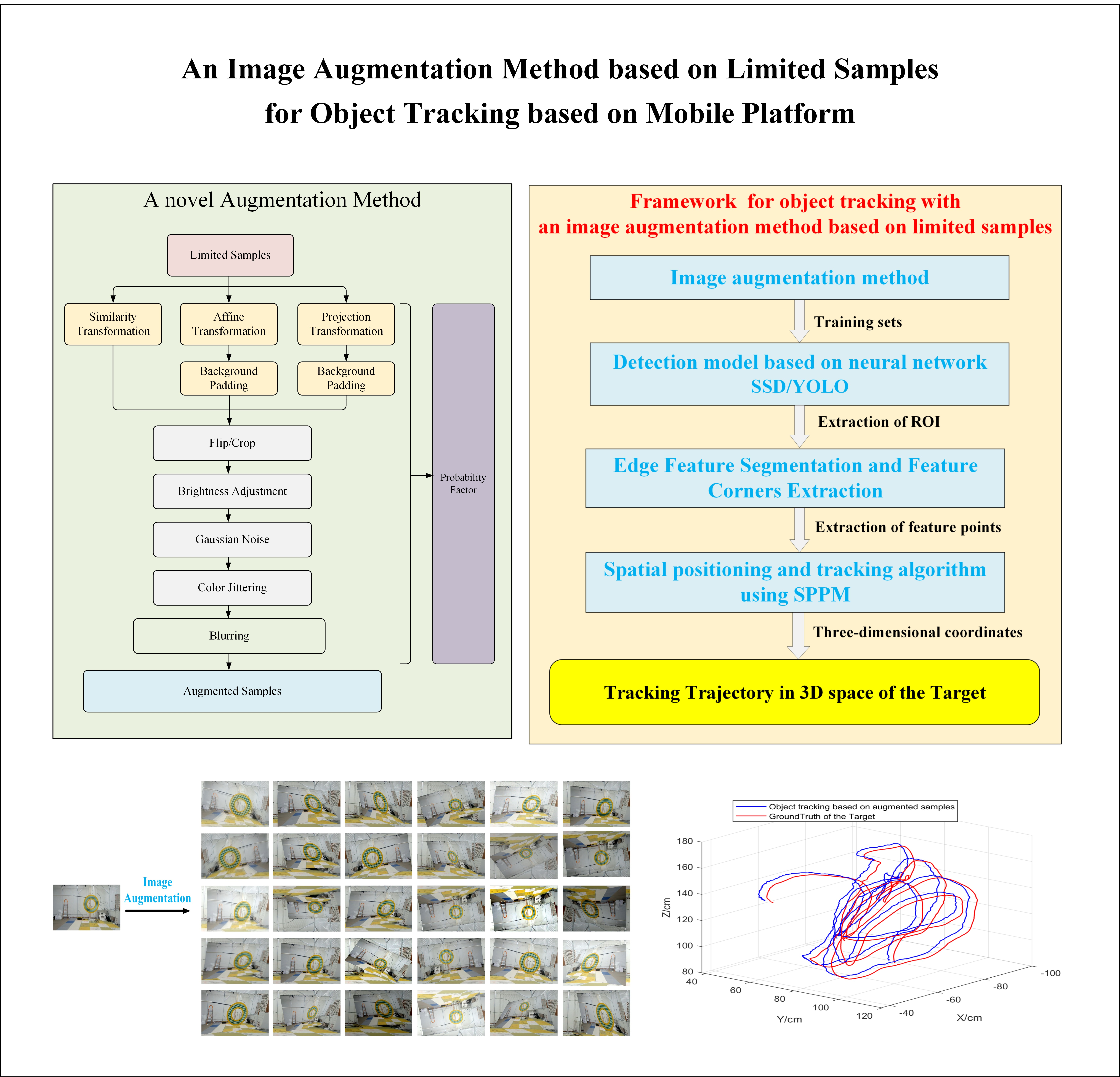
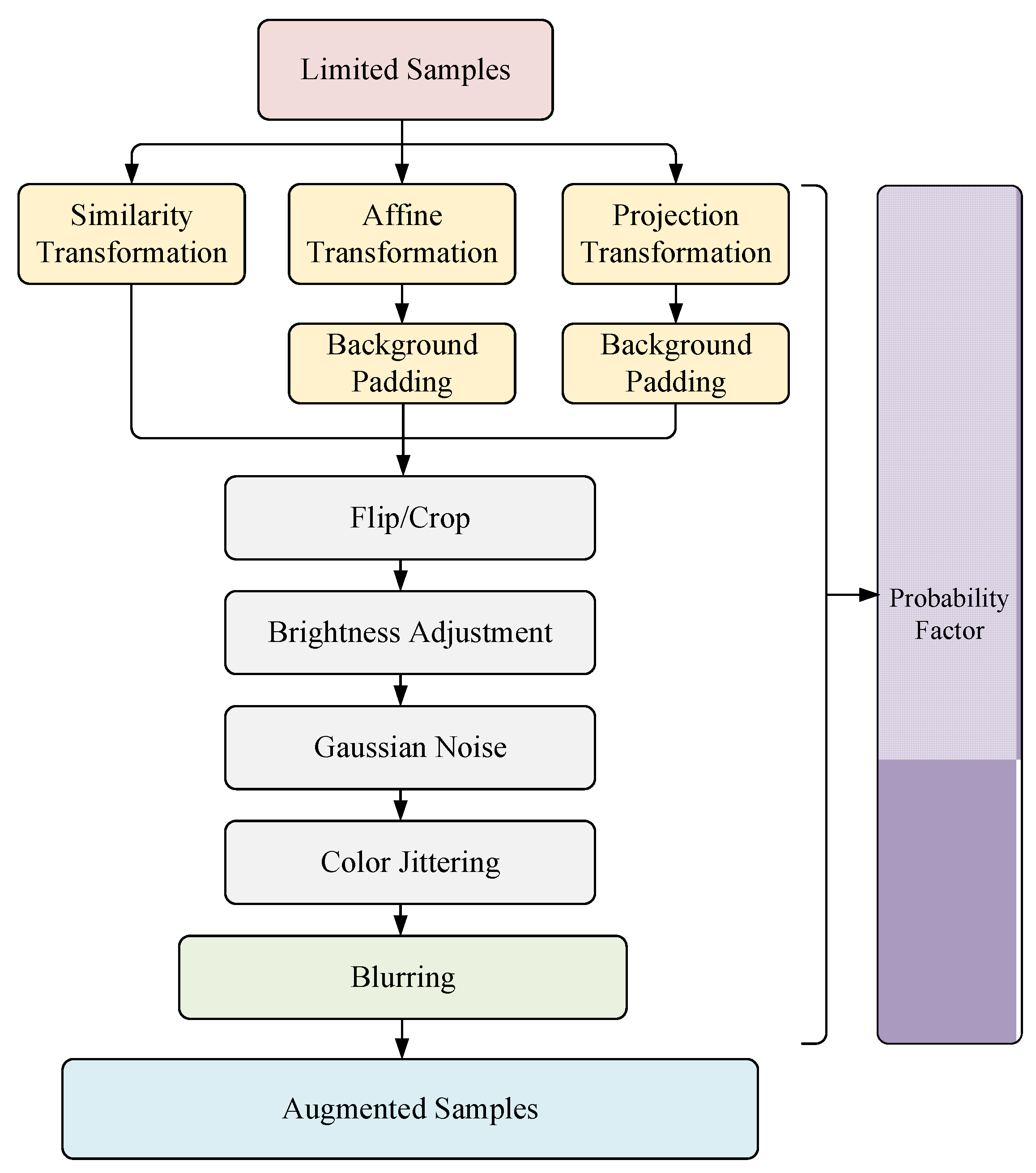
3.1. Overall Framework
3.2. Transformations
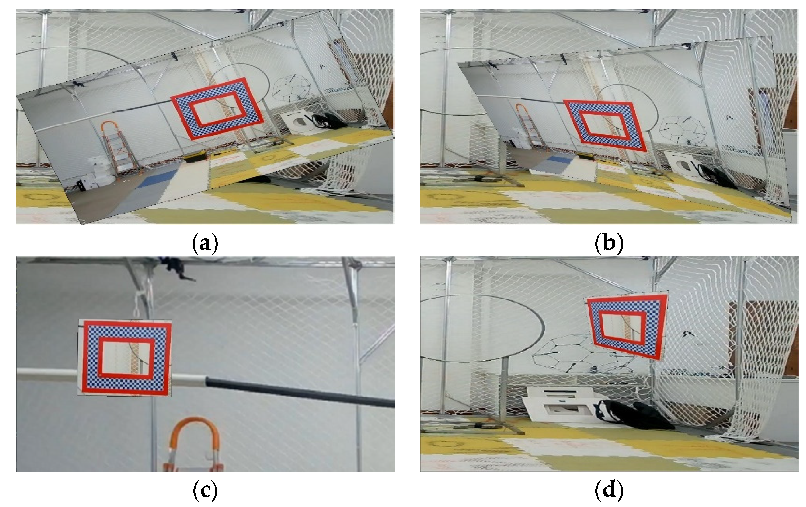
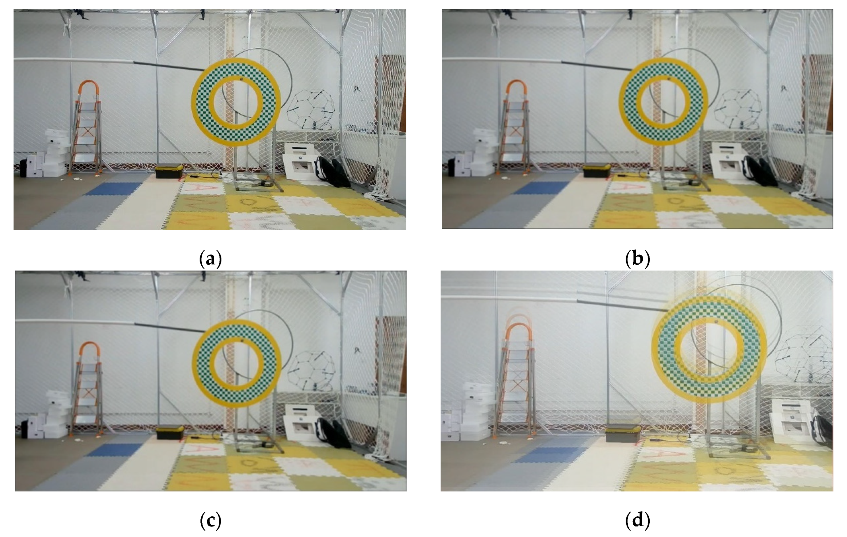
3.2.1. Affine Augmentation
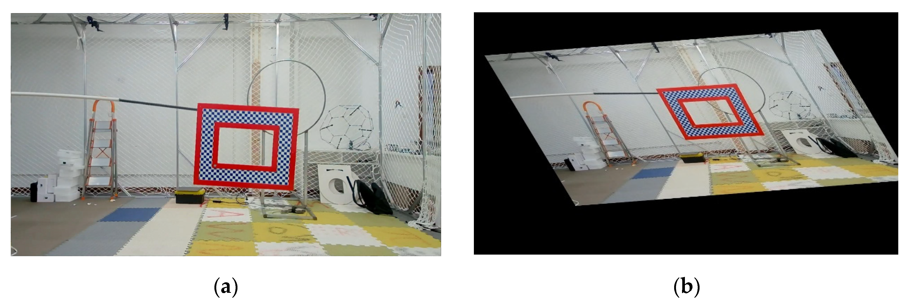
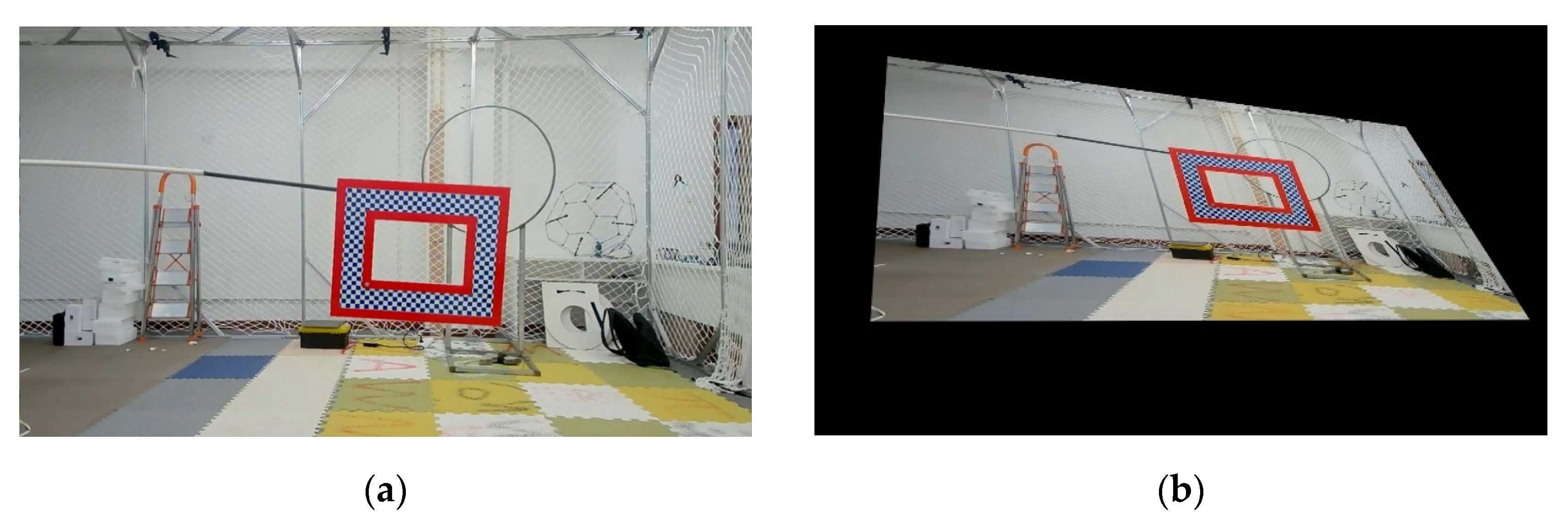
3.2.2. Projection Augmentation
3.3. Background Padding for Affine and Projection
3.4. Blurring Augmentation
3.5. Probability Factors
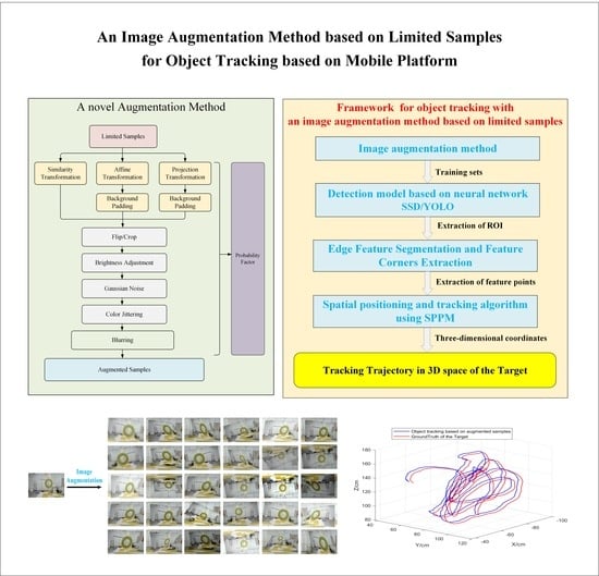
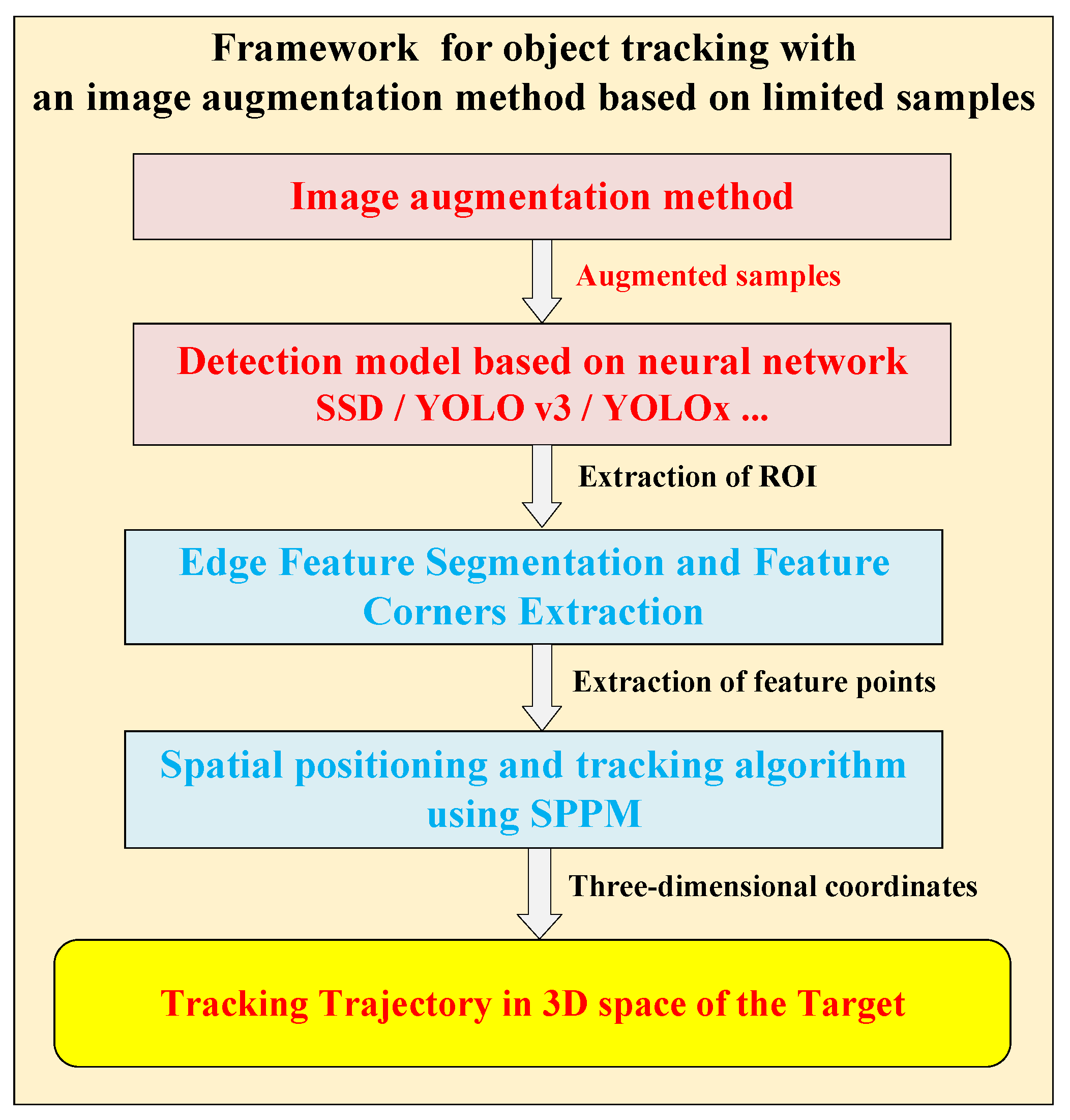
3.6. Framework for Object Tracking Based on Motion Platform
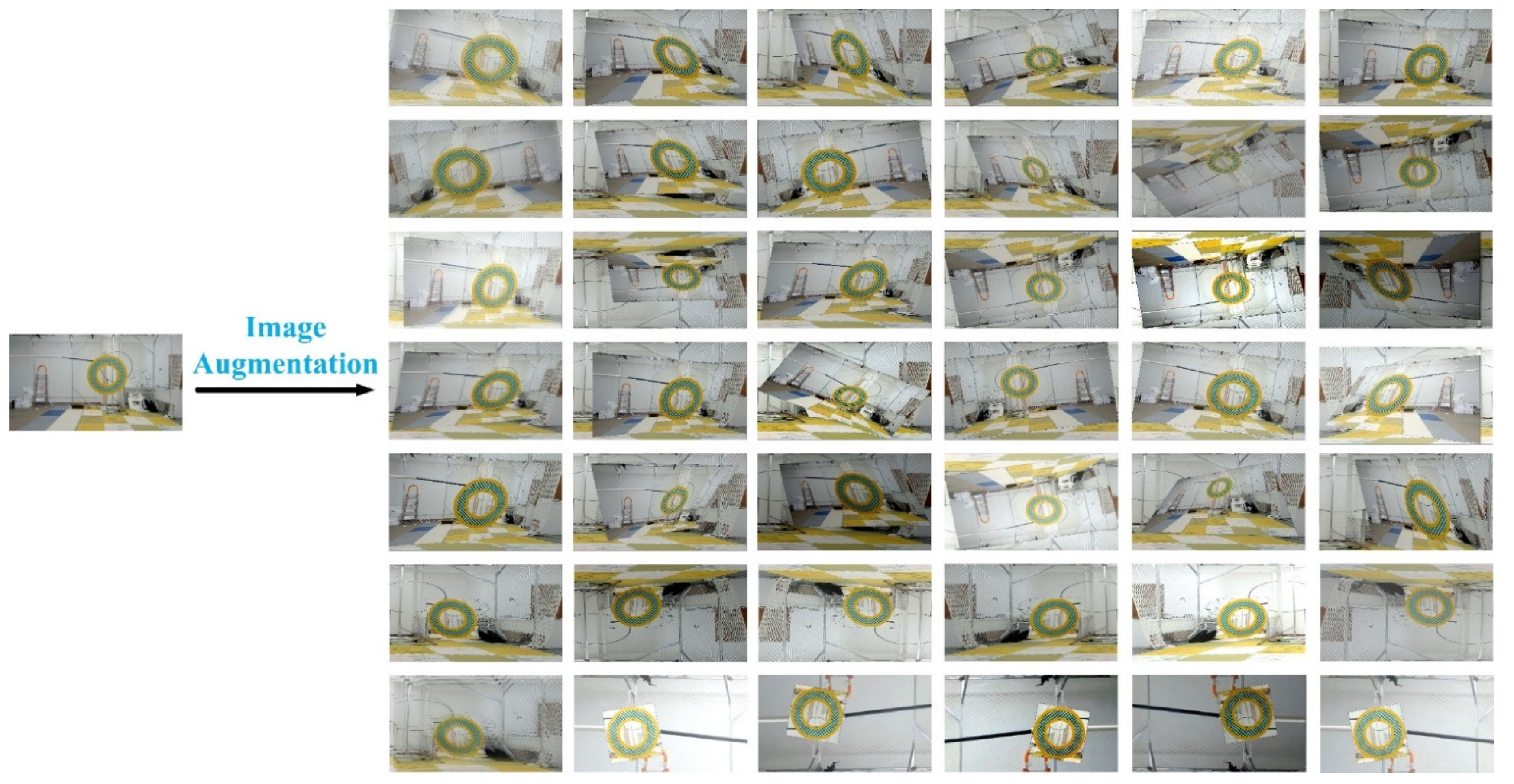
- Image augmentation module: Based on a small amount of sample sets, affine transformation and projection transformation are firstly used to simulate the rotation of the object in the frame. Then the multi-direction blur algorithm is used to simulate the blurring caused by the jitter of the sensor platform and the high-speed object. Finally, the general augmentation model and augmentation probability factors are combined to realize the augmentation tasks of the sample;
- Neural network detection model: The augmented samples are put into the neural network model for training to obtain the network parameters and extract the ROI anchor frame area of the object. This experiment adopts SSD and YOLOv3 models;
- Object feature segmentation and keypoints extraction algorithm: According to the needs of different object types and tracking tasks, the objects in the ROI are further segmented and extracted to obtain the required features. The neural networks at the level of semantic segmentation, such as U-Net [29], or traditional image processing methods can be adopted;
- Three-dimensional positioning algorithm: The SPPM method is adopted to quickly solve the depth value of the object feature point, in order to obtain the spatial coordinates of the object and finally acquire the spatial trajectory information of the object. In the author’s previous work [19,20,30,31], we discuss in detail object feature extraction and detection (FDA-SSD), planar feature moving object localization method (SPPM), and an autonomous localization method for motion platforms based on object tracking (MLSS-VO) respectively. In order not to distract the reader, we will not elaborate on what has been published in the manuscript, instead, we will focus on the elaboration of the image augmentation method. Therefore, the correlation between object tracking and SLAM can refer to the author’s previous research results.
4. Experiments
- (1)
- The angular range of geometric transformation augmentation
- (2)
- The number of stacks that controls the multi-directional stack blur augmentation degree = 3; pixel step size ; transparency parameter .
- (3)
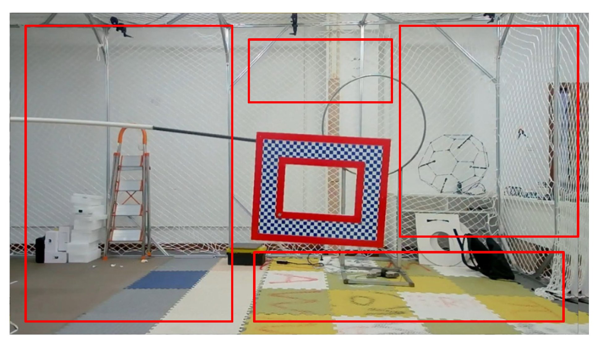
- The cropping size for random background padding, we recommend using a background with a side length greater than 100 pixels and an aspect ratio close to the original image ratio.
- (4)
- Probabilistic augmentation factor , since we are discussing augmentation methods for small sample sets. The selection of the probability factor depends on the characteristic environment. In Section 3.5, we supplement the value suggestion of the probability factor.
5. Conclusions
Author Contributions
Funding
Institutional Review Board Statement
Informed Consent Statement
Data Availability Statement
Conflicts of Interest
References
- LeCun, Y.; Bottou, L.; Bengio, Y.; Haffner, P. Gradient-based learning applied to document recognition. Proc. IEEE 1998, 86, 2278–2324. [Google Scholar] [CrossRef] [Green Version]
- Krizhevsky, A.; Sutskever, I.; Hinton, G.E. Imagenet classification with deep convolutional neural networks. Adv. Neural Inf. Process. Syst. 2012, 25. [Google Scholar] [CrossRef]
- Simonyan, K.; Zisserman, A. Very deep convolutional networks for large-scale image recognition. arXiv 2014, arXiv:1409.1556. [Google Scholar]
- Szegedy, C.; Liu, W.; Jia, Y.; Sermanet, P.; Reed, S.; Anguelov, D.; Erhan, D.; Vanhoucke, V.; Rabinovich, A. Going deeper with convolutions. In Proceedings of the IEEE Conference on Computer Vision and Pattern Recognition, Boston, MA, USA, 7–12 June 2015; pp. 1–9. [Google Scholar]
- He, K.; Zhang, X.; Ren, S.; Sun, J. Deep residual learning for image recognition. In Proceedings of the IEEE Conference on Computer Vision and Pattern Recognition, Las Vegas, NV, USA, 27–30 June 2016; pp. 770–778. [Google Scholar]
- Huang, G.; Liu, Z.; Van Der Maaten, L.; Weinberger, K.Q. Densely connected convolutional networks. In Proceedings of the IEEE Conference on Computer Vision and Pattern Recognition, Honolulu, HI, USA, 21–26 July 2017; pp. 4700–4708. [Google Scholar]
- Hussain, Z.; Gimenez, F.; Yi, D.; Rubin, D. Differential data augmentation techniques for medical imaging classification tasks. AMIA Annu. Symp. Proc. 2017, 2017, 979–984. [Google Scholar] [PubMed]
- Yun, S.; Han, D.; Oh, S.J.; Chun, S.; Choe, J.; Yoo, Y. Cutmix: Regularization strategy to train strong classifiers with localizable features. In Proceedings of the IEEE/CVF International Conference on Computer Vision, Long Beach, CA, USA, 15–20 June 2019; pp. 6023–6032. [Google Scholar]
- Bochkovskiy, A.; Wang, C.-Y.; Liao, H.-Y.M. Yolov4: Optimal speed and accuracy of object detection. arXiv 2020, arXiv:2004.10934. [Google Scholar]
- Zhang, H.; Cisse, M.; Dauphin, Y.N.; Lopez-Paz, D. mixup: Beyond empirical risk minimization. arXiv 2017, arXiv:1710.09412. [Google Scholar]
- Ge, Z.; Liu, S.; Wang, F.; Li, Z.; Sun, J. Yolox: Exceeding yolo series in 2021. arXiv 2021, arXiv:2107.08430. [Google Scholar]
- Zhong, Z.; Zheng, L.; Kang, G.; Li, S.; Yang, Y. Random erasing data augmentation. In Proceedings of the AAAI Conference on Artificial Intelligence, New York, NY, USA, 7–12 February 2020; pp. 13001–13008. [Google Scholar]
- Inoue, H. Data augmentation by pairing samples for images classification. arXiv 2018, arXiv:1801.02929. [Google Scholar]
- Kiran, B.R.; Sobh, I.; Talpaert, V.; Mannion, P.; Al Sallab, A.A.; Yogamani, S.; Pérez, P. Deep reinforcement learning for autonomous driving: A survey. IEEE Trans. Intell. Transp. Syst. 2021. [Google Scholar] [CrossRef]
- Zhuang, F.; Qi, Z.; Duan, K.; Xi, D.; Zhu, Y.; Zhu, H.; Xiong, H.; He, Q. A comprehensive survey on transfer learning. Proc. IEEE 2020, 109, 43–76. [Google Scholar] [CrossRef]
- Cubuk, E.D.; Zoph, B.; Mane, D.; Vasudevan, V.; Le, Q.V. Autoaugment: Learning augmentation strategies from data. In Proceedings of the IEEE/CVF Conference on Computer Vision and Pattern Recognition, Long Beach, CA, USA, 15–20 June 2019; pp. 113–123. [Google Scholar]
- Cubuk, E.D.; Zoph, B.; Shlens, J.; Le, Q.V. Randaugment: Practical automated data augmentation with a reduced search space. In Proceedings of the IEEE/CVF Conference on Computer Vision and Pattern Recognition Workshops, Seattle, WA, USA, 14–19 June 2020; pp. 702–703. [Google Scholar]
- Niemeyer, M.; Geiger, A. Giraffe: Representing scenes as compositional generative neural feature fields. In Proceedings of the IEEE/CVF Conference on Computer Vision and Pattern Recognition, Nashville, TN, USA, 20–25 June 2021; pp. 11453–11464. [Google Scholar]
- Wang, Z.-H.; Chen, W.-J.; Qin, K.-Y. Dynamic Target Tracking and Ingressing of a Small UAV Using Monocular Sensor Based on the Geometric Constraints. Electronics 2021, 10, 1931. [Google Scholar] [CrossRef]
- Wang, Z.; Yang, S.; Shi, M.; Qin, K. FDA-SSD: Fast Depth-Assisted Single-Shot MultiBox Detector for 3D Tracking Based on Monocular Vision. Appl. Sci. 2022, 12, 1164. [Google Scholar] [CrossRef]
- Wu, Y.; Lim, J.; Yang, M.-H. Online object tracking: A benchmark. In Proceedings of the IEEE conference on computer vision and pattern recognition, Portland, OR, USA, 23–28 June 2013; pp. 2411–2418. [Google Scholar]
- Wu, Y.; Lim, J.; Yang, M. Object Tracking Benchmark. IEEE Trans. Pattern Anal. Mach. Intell. 2015, 37, 1834–1848. [Google Scholar] [CrossRef] [PubMed] [Green Version]
- Sharma, J.R.; Gupta, P. An efficient fifth order method for solving systems of nonlinear equations. Comput. Math. Appl. 2014, 67, 591–601. [Google Scholar] [CrossRef]
- Redmon, J.; Farhadi, A. Yolov3: An incremental improvement. arXiv 2018, arXiv:1804.02767. [Google Scholar]
- Liu, W.; Anguelov, D.; Erhan, D.; Szegedy, C.; Reed, S.; Fu, C.Y.; Berg, A.C. Ssd: Single shot multibox detector. In Proceedings of the European Conference on Computer Vision, Amsterdam, The Netherlands, 8–16 October 2016; pp. 21–37. [Google Scholar]
- Redmon, J.; Divvala, S.; Girshick, R.; Farhadi, A. You only look once: Unified, real-time object detection. In Proceedings of the IEEE Conference on Computer Vision and Pattern Recognition, Las Vegas, NV, USA, 27–30 June 2016; pp. 779–788. [Google Scholar]
- Ren, S.; He, K.; Girshick, R.; Sun, J. Faster r-cnn: Towards real-time object detection with region proposal networks. Adv. Neural Inf. Process. Syst. 2015, 28, 91–99. [Google Scholar] [CrossRef] [PubMed] [Green Version]
- Buslaev, A.; Iglovikov, V.I.; Khvedchenya, E.; Parinov, A.; Druzhinin, M.; Kalinin, A.A. Albumentations: Fast and flexible image augmentations. Information 2020, 11, 125. [Google Scholar] [CrossRef] [Green Version]
- Ronneberger, O.; Fischer, P.; Brox, T. U-net: Convolutional networks for biomedical image segmentation. In Proceedings of the International Conference on Medical Image Computing and Computer-Assisted Intervention, Munich, Germany, 5–9 October 2015; pp. 234–241. [Google Scholar]
- Wang, Z.; Yang, S.; Shi, M.; Qin, K. MLSS-VO: A Multi-Level Scale Stabilizer with Self-Supervised Features for Monocular Visual Odometry in Target Tracking. Electronics 2022, 11, 223. [Google Scholar] [CrossRef]
- Wang, Z.H.; Qin, K.Y.; Zhang, T.; Zhu, B. An Intelligent Ground-Air Cooperative Navigation Framework Based on Visual-Aided Method in Indoor Environments. Unmanned Syst. 2021, 9, 237–246. [Google Scholar] [CrossRef]


| Augmentations | Building Method | Advantages | Disadvantages |
|---|---|---|---|
| Augmentation based on general detection model | Use augmented modules in existing detection models (SSD, Yolo v4, Yolo x, etc.) | End-to-end augmentation; no redundant design required. | Augmentation may not be ideal in certain scenarios; detection scenarios with insufficient samples are not applicable. |
| Our Augmentation framework | A suitable augmented model is constructed for the needs of object rotation and imaging blur in the mobile platform. | Targeted for object tracking scenarios; Suitable for scenarios with fewer pre-training samples. | The construction of the augmented model needs to analyze the characteristics of the scene; the construction process is relatively cumbersome. |
| No. | Scenarios | Geometric Transformation | Brightness Adjustment | Flip | Crop | Gaussian Noise | Color Jittering | Burring |
|---|---|---|---|---|---|---|---|---|
| 1 | Unknown scene | 0.5 | 0.5 | 0.5 | 0.2 | 0.2 | 0.2 | 0.5 |
| 2 | Indoor/Object rotation/Platform shake | 0.8 | 0.1 | 0.5 | 0.1 | 0.1 | 0.1 | 0.8 |
| 3 | Indoor/Object occlusion/High-speed moving object | 0.5 | 0.1 | 0.5 | 0.6 | 0.1 | 0.1 | 0.8 |
| 4 | Outdoor short-term tracking/No rotation/Platform shaking | 0.3 | 0.5 | 0.1 | 0.2 | 0.3 | 0.3 | 0.8 |
| 5 | Outdoor long-term tracking/Object rotation/Fixed platform | 0.8 | 0.8 | 0.5 | 0.2 | 0.3 | 0.3 | 0.4 |
| Methods | Datasets | Input Resolution | Augmented | mAP50 | mAP75 |
|---|---|---|---|---|---|
| SSD | OTB100-Toy | 320 × 240 | Yes | 0.729 | 0.583 |
| SSD | OTB100-Toy | 320 × 240 | No | 0.608 | 0.510 |
| SSD | OTMP-Grid-like Circle | 1280 × 720 | Yes | 0.893 | 0.781 |
| SSD | OTMP-Grid-like Circle | 1280 × 720 | No | 0.596 | 0.472 |
| YOLOv3 | OTB100-Toy | 320 × 240 | Yes | 0.752 | 0.598 |
| YOLOv3 | OTB100-Toy | 320 × 240 | No | 0.648 | 0.521 |
| YOLOv3 | OTMP-Grid-like Circle | 1280 × 720 | Yes | 0.913 | 0.841 |
| YOLOv3 | OTMP-Grid-like Circle | 1280 × 720 | No | 0.692 | 0.575 |
| YOLOv4 | OTB100-Toy | 320 × 240 | Yes | 0.791 | 0.648 |
| YOLOv4 | OTB100-Toy | 320 × 240 | No | 0.672 | 0.560 |
| YOLOv4 | OTMP-Grid-like Circle | 1280 × 720 | Yes | 0.924 | 0.822 |
| YOLOv4 | OTMP-Grid-like Circle | 1280 × 720 | No | 0.801 | 0.611 |
| YOLOx | OTB100-Toy | 320 × 240 | Yes | 0.789 | 0.638 |
| YOLOx | OTB100-Toy | 320 × 240 | No | 0.633 | 0.564 |
| YOLOx | OTMP-Grid-like Circle | 1280 × 720 | Yes | 0.936 | 0.851 |
| YOLOx | OTMP-Grid-like Circle | 1280 × 720 | No | 0.812 | 0.632 |
| Methods | Datasets | Input Resolution | Affine & Projection | mAP50 | mAP75 |
|---|---|---|---|---|---|
| SSD | OTB50-Liquor | 640 × 480 | Yes | 0.821 | 0.747 |
| SSD | OTB50-Liquor | 640 × 480 | No | 0.737 | 0.622 |
| SSD | OTMP-Grid-like Circle | 1280 × 720 | Yes | 0.893 | 0.781 |
| SSD | OTMP-Grid-like Circle | 1280 × 720 | No | 0.640 | 0.517 |
| YOLOv3 | OTB50-Liquor | 640 × 480 | Yes | 0.837 | 0.737 |
| YOLOv3 | OTB50-Liquor | 640 × 480 | No | 0.778 | 0.672 |
| YOLOv3 | OTMP-Grid-like Circle | 1280 × 720 | Yes | 0.913 | 0.841 |
| YOLOv3 | OTMP-Grid-like Circle | 1280 × 720 | No | 0.602 | 0.512 |
| YOLOv4 | OTB50-Liquor | 640 × 480 | Yes | 0.886 | 0.780 |
| YOLOv4 | OTB50-Liquor | 640 × 480 | No | 0.792 | 0.705 |
| YOLOv4 | OTMP-Grid-like Circle | 1280 × 720 | Yes | 0.924 | 0.822 |
| YOLOv4 | OTMP-Grid-like Circle | 1280 × 720 | No | 0.840 | 0.657 |
| YOLOx | OTB50-Liquor | 640 × 480 | Yes | 0.878 | 0.789 |
| YOLOx | OTB50-Liquor | 640 × 480 | No | 0.784 | 0.712 |
| YOLOx | OTMP-Grid-like Circle | 1280 × 720 | Yes | 0.936 | 0.851 |
| YOLOx | OTMP-Grid-like Circle | 1280 × 720 | No | 0.839 | 0.660 |
| Methods | Datasets | Input Resolution | Background Padding | mAP50 | mAP75 |
|---|---|---|---|---|---|
| SSD | OTB50-Liquor | 640 × 480 | Yes | 0.821 | 0.747 |
| SSD | OTB50-Liquor | 640 × 480 | No | 0.817 | 0.728 |
| SSD | OTMP-Grid-like Circle | 1280 × 720 | Yes | 0.893 | 0.781 |
| SSD | OTMP-Grid-like Circle | 1280 × 720 | No | 0.870 | 0.785 |
| YOLOv3 | OTB50-Liquor | 640 × 480 | Yes | 0.837 | 0.737 |
| YOLOv3 | OTB50-Liquor | 640 × 480 | No | 0.815 | 0.712 |
| YOLOv3 | OTMP-Grid-like Circle | 1280 × 720 | Yes | 0.913 | 0.841 |
| YOLOv3 | OTMP-Grid-like Circle | 1280 × 720 | No | 0.901 | 0.838 |
| YOLOv4 | OTB50-Liquor | 640 × 480 | Yes | 0.886 | 0.780 |
| YOLOv4 | OTB50-Liquor | 640 × 480 | No | 0.872 | 0.778 |
| YOLOv4 | OTMP-Grid-like Circle | 1280 × 720 | Yes | 0.924 | 0.822 |
| YOLOv4 | OTMP-Grid-like Circle | 1280 × 720 | No | 0.915 | 0.817 |
| YOLOx | OTB50-Liquor | 640 × 480 | Yes | 0.878 | 0.789 |
| YOLOx | OTB50-Liquor | 640 × 480 | No | 0.851 | 0.768 |
| YOLOx | OTMP-Grid-like Circle | 1280 × 720 | Yes | 0.936 | 0.851 |
| YOLOx | OTMP-Grid-like Circle | 1280 × 720 | No | 0.932 | 0.847 |
| Methods | Datasets | Input Resolution | Blurring | mAP50 | mAP75 |
|---|---|---|---|---|---|
| SSD | OTB50-BlurOwl | 640 × 480 | Yes | 0.731 | 0.649 |
| SSD | OTB50-BlurOwl | 640 × 480 | No | 0.610 | 0.508 |
| SSD | OTMP-Grid-like Circle | 1280 × 720 | Yes | 0.893 | 0.781 |
| SSD | OTMP-Grid-like Circle | 1280 × 720 | No | 0.801 | 0.714 |
| YOLOv3 | OTB50-BlurOwl | 640 × 480 | Yes | 0.726 | 0.660 |
| YOLOv3 | OTB50-BlurOwl | 640 × 480 | No | 0.636 | 0.462 |
| YOLOv3 | OTMP-Grid-like Circle | 1280 × 720 | Yes | 0.913 | 0.841 |
| YOLOv3 | OTMP-Grid-like Circle | 1280 × 720 | No | 0.821 | 0.730 |
| YOLOv4 | OTB50-BlurOwl | 320 × 240 | Yes | 0.782 | 0.629 |
| YOLOv4 | OTB50-BlurOwl | 320 × 240 | No | 0.712 | 0.554 |
| YOLOv4 | OTMP-Grid-like Circle | 1280 × 720 | Yes | 0.924 | 0.822 |
| YOLOv4 | OTMP-Grid-like Circle | 1280 × 720 | No | 0.873 | 0.766 |
| YOLOx | OTB50-BlurOwl | 320 × 240 | Yes | 0.802 | 0.673 |
| YOLOx | OTB50-BlurOwl | 320 × 240 | No | 0.743 | 0.630 |
| YOLOx | OTMP-Grid-like Circle | 1280 × 720 | Yes | 0.936 | 0.851 |
| YOLOx | OTMP-Grid-like Circle | 1280 × 720 | No | 0.878 | 0.807 |
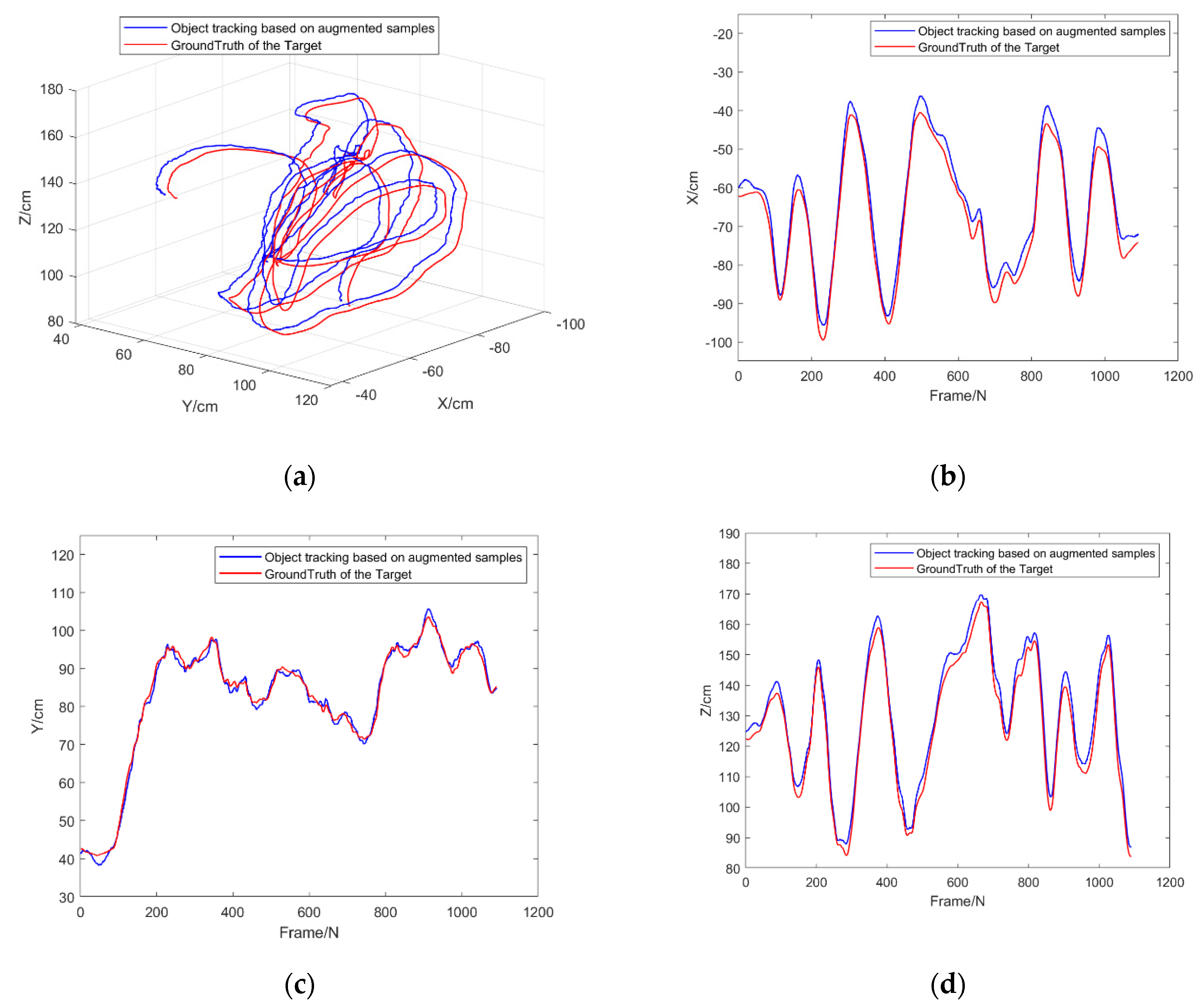
| Axis | X [cm] | Y [cm] | Z [cm] |
|---|---|---|---|
| RMSE | 4.15 | 3.18 | 4.21 |
Publisher’s Note: MDPI stays neutral with regard to jurisdictional claims in published maps and institutional affiliations. |
© 2022 by the authors. Licensee MDPI, Basel, Switzerland. This article is an open access article distributed under the terms and conditions of the Creative Commons Attribution (CC BY) license (https://creativecommons.org/licenses/by/4.0/).
Share and Cite
Wang, Z.; Yang, S.; Shi, M.; Qin, K. An Image Augmentation Method Based on Limited Samples for Object Tracking Based on Mobile Platform. Sensors 2022, 22, 1967. https://doi.org/10.3390/s22051967
Wang Z, Yang S, Shi M, Qin K. An Image Augmentation Method Based on Limited Samples for Object Tracking Based on Mobile Platform. Sensors. 2022; 22(5):1967. https://doi.org/10.3390/s22051967
Chicago/Turabian StyleWang, Zihao, Sen Yang, Mengji Shi, and Kaiyu Qin. 2022. "An Image Augmentation Method Based on Limited Samples for Object Tracking Based on Mobile Platform" Sensors 22, no. 5: 1967. https://doi.org/10.3390/s22051967
APA StyleWang, Z., Yang, S., Shi, M., & Qin, K. (2022). An Image Augmentation Method Based on Limited Samples for Object Tracking Based on Mobile Platform. Sensors, 22(5), 1967. https://doi.org/10.3390/s22051967