
Precise Target Geo-Location of Long-Range Oblique Reconnaissance System for UAVs

Abstract
:1. Introduction
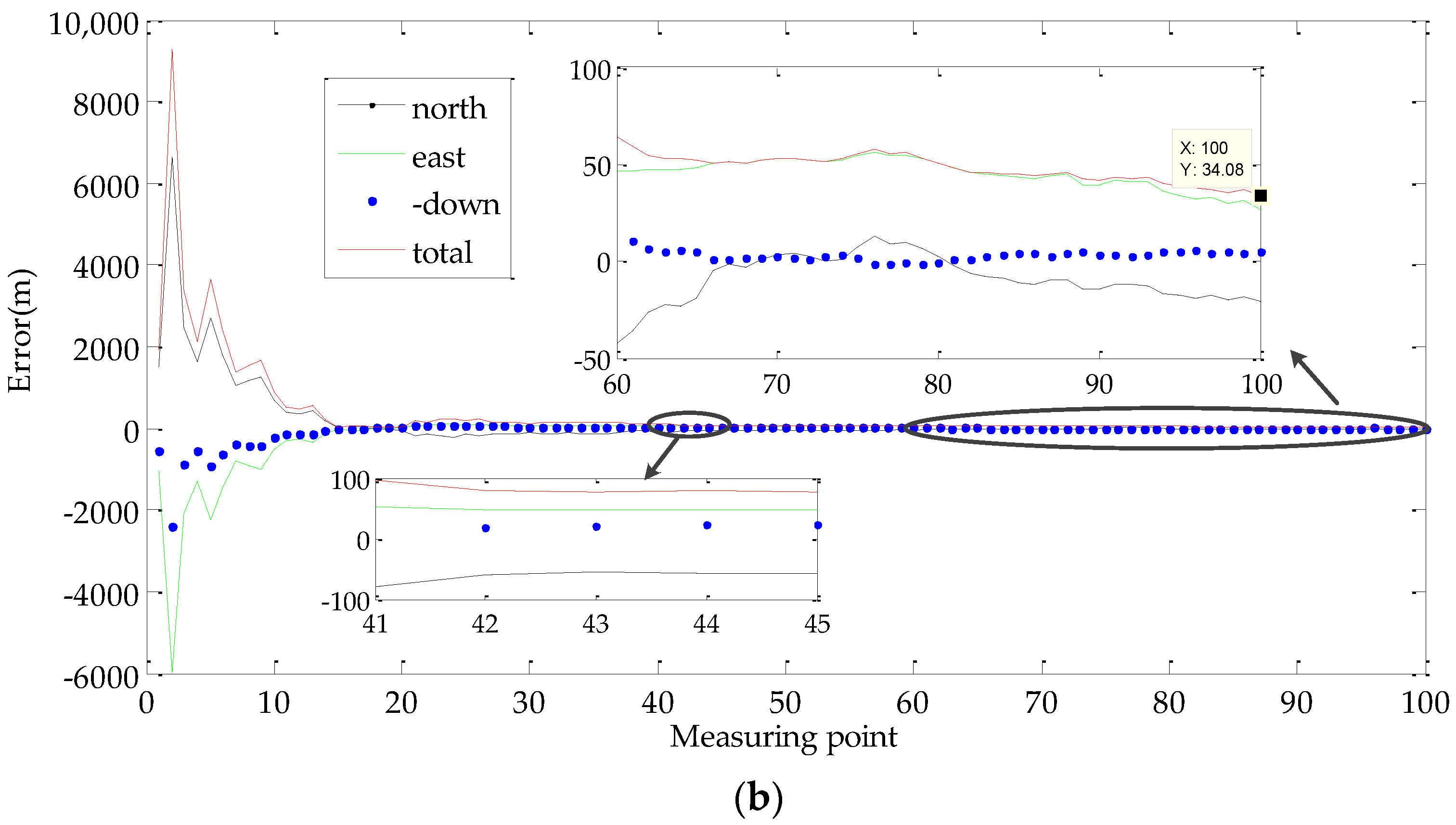
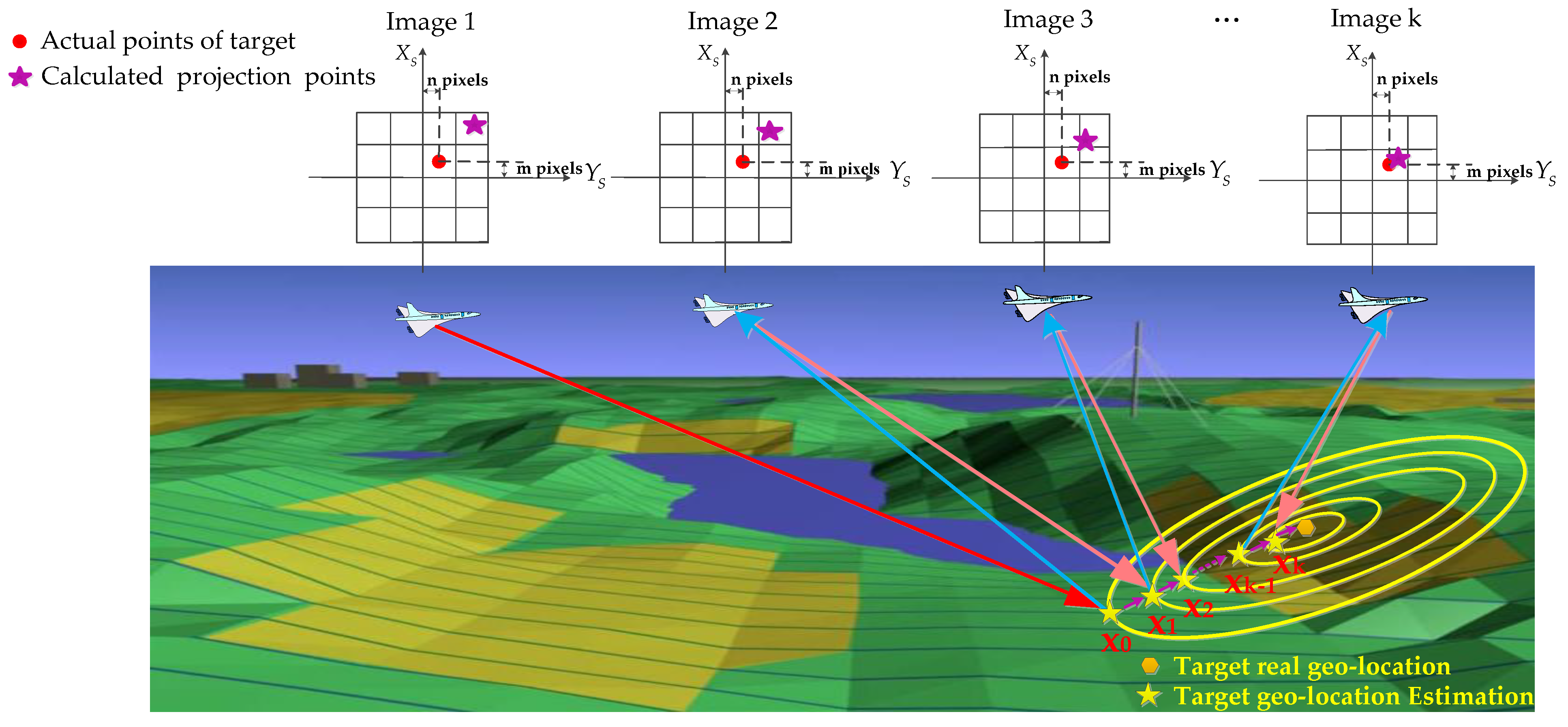
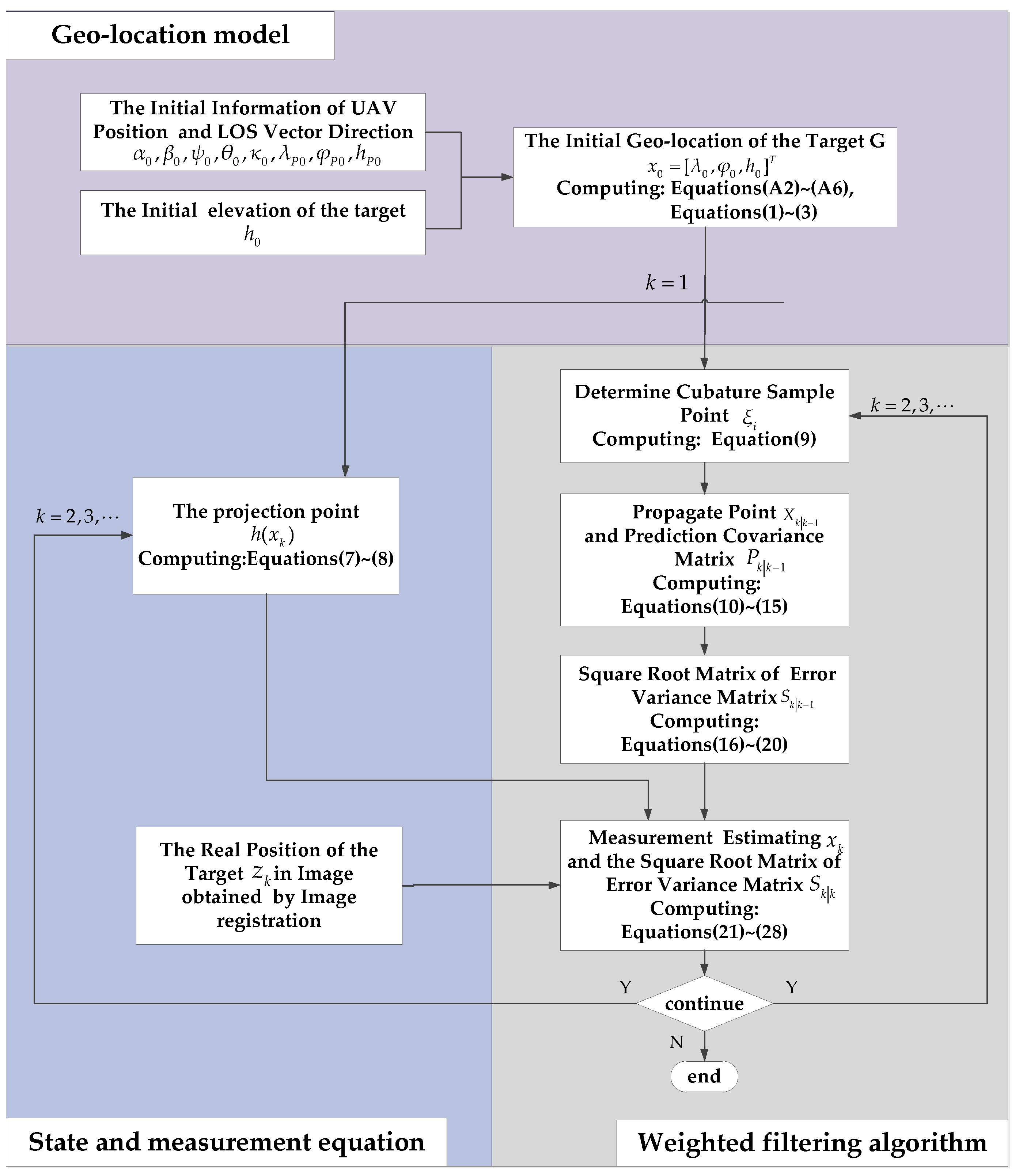
- Based on a comparative analysis of the present methods affecting geo-location accuracy, a set of work patterns and a novel geo-location method are proposed in this paper to address these problems. There is an iterative process in the proposed method, and the geo-location accuracy is improved greatly by repeatedly imaging the same stationary target point. In brief, the procedure can be summarized by the following: Step 1, calculate the rough geo-location of the target using the traditional method. Step 2, based the rough geo-location of the target, adjust the position of the gimbal and reimage the target. Step 3, process the reprojection errors and obtain optimized target geo-location. Repeat the above process; after several iterations, the estimated geo-location converges on the true value.
- Compared with the traditional method, the proposed method does not rely on the accuracy of GPS/INS and target elevation, which are regarded as the key error sources in the traditional method. Compared with the laser range finder method, the proposed method is not limited by laser ranging distance. Compared with the DEM method and image method, high-precision real-time geo-location can be realized without DEM or geographic reference data. Compared with cooperative localization between UAVs, the proposed method can achieve high precision without multiple UAVs.
- The proposed method can achieve high precision, without high-precision GPS/INS, multiple UAVs, and geographic reference data, such as a standard map, DEM, and so on. The proposed method has strong timeliness and a more extensive application value in practical engineering.
2. Geo-Location Method Based on WGS-84 Ellipsoidal Earth Model
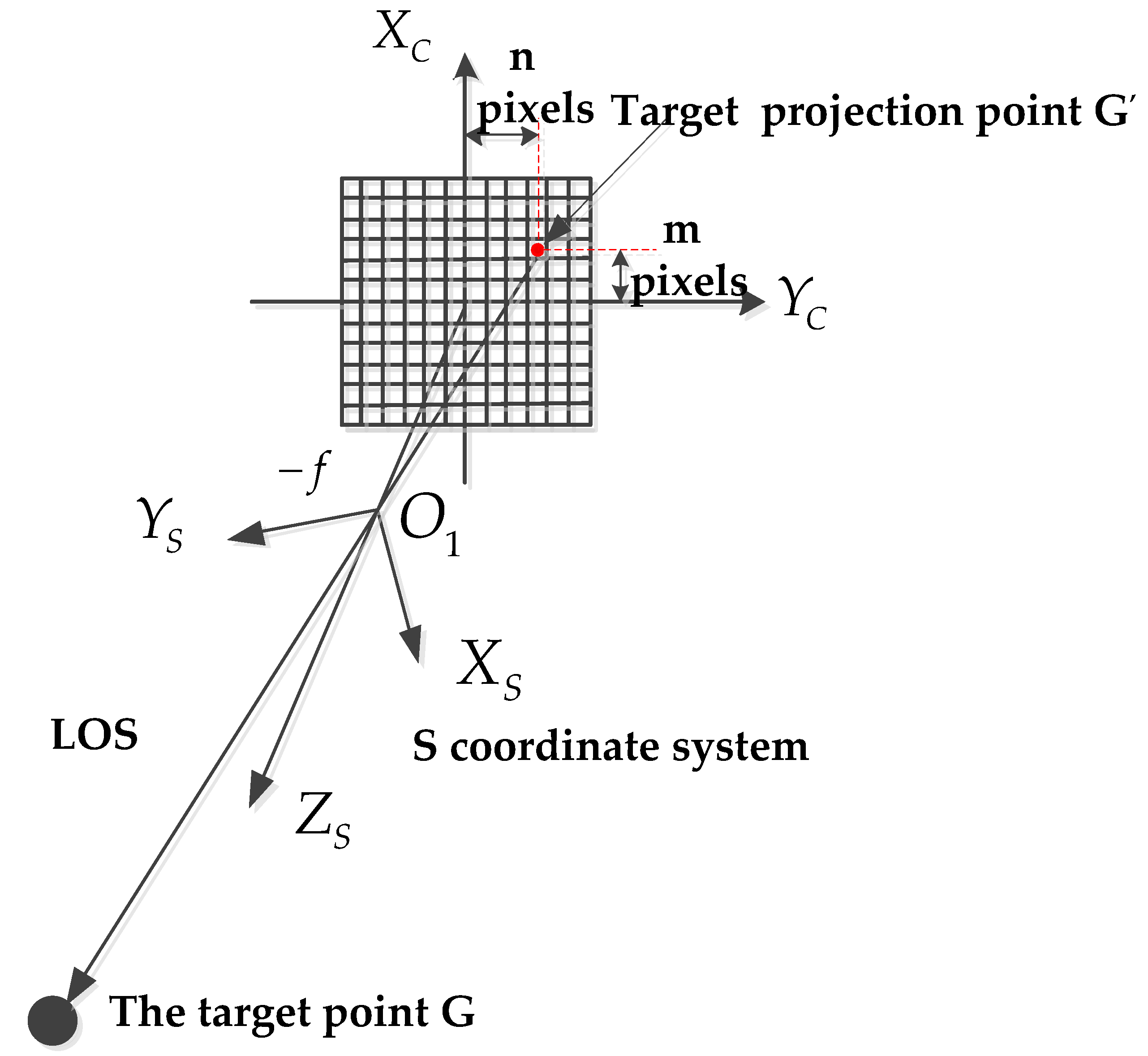
2.1. Geo-Location Model using the Traditional Method
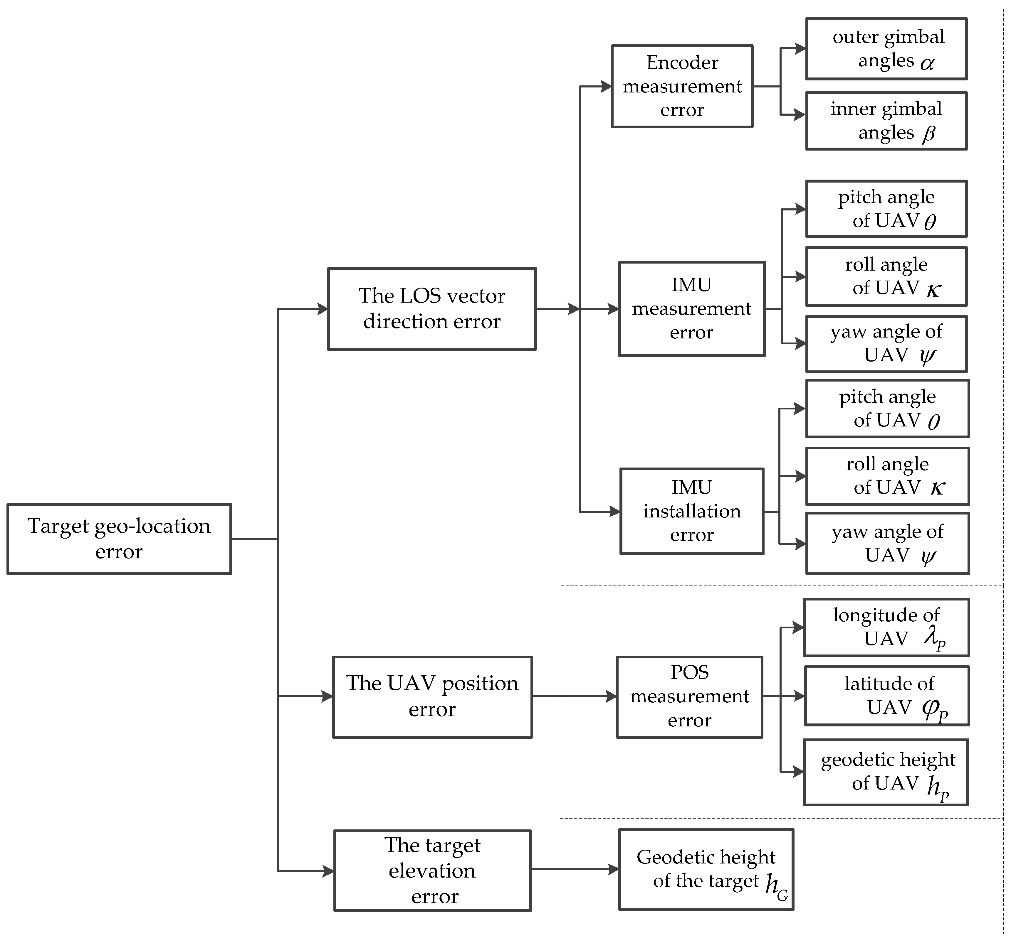
2.2. The Sources of Influence in the Traditional Method on Geo-Location Accuracy
3. The Proposed Geo-Location Method
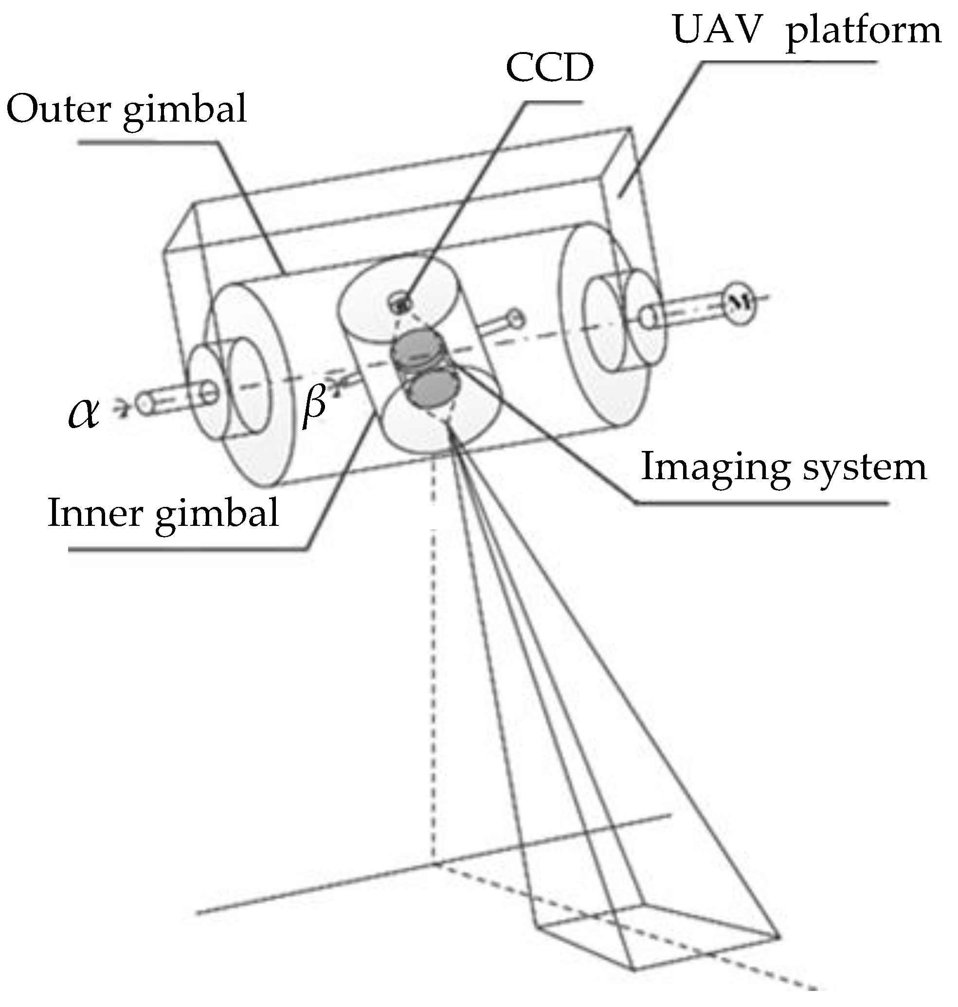
3.1. The Work Pattern of LRORS
3.2. The Proposed Algorithm
4. Experiments
4.1. Simulation
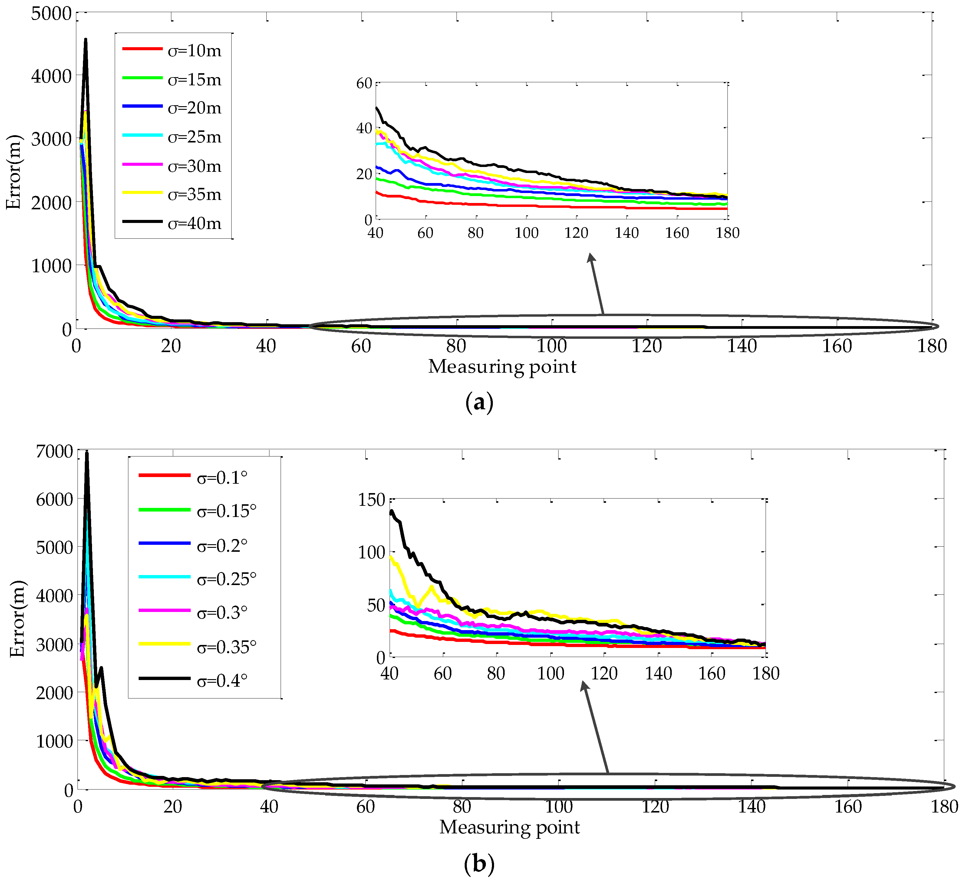
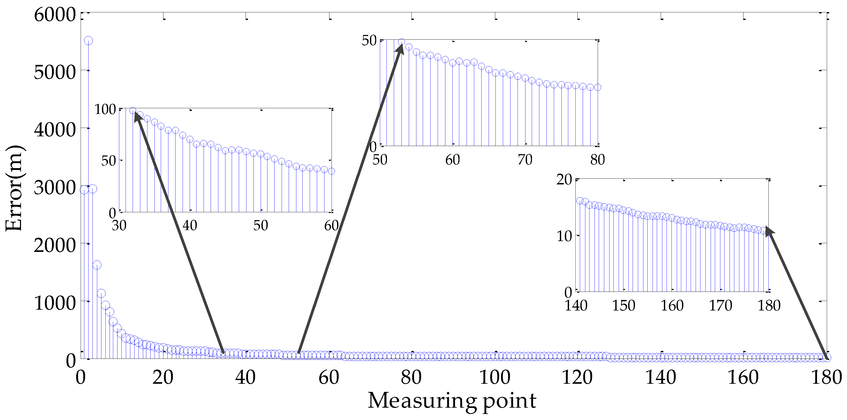
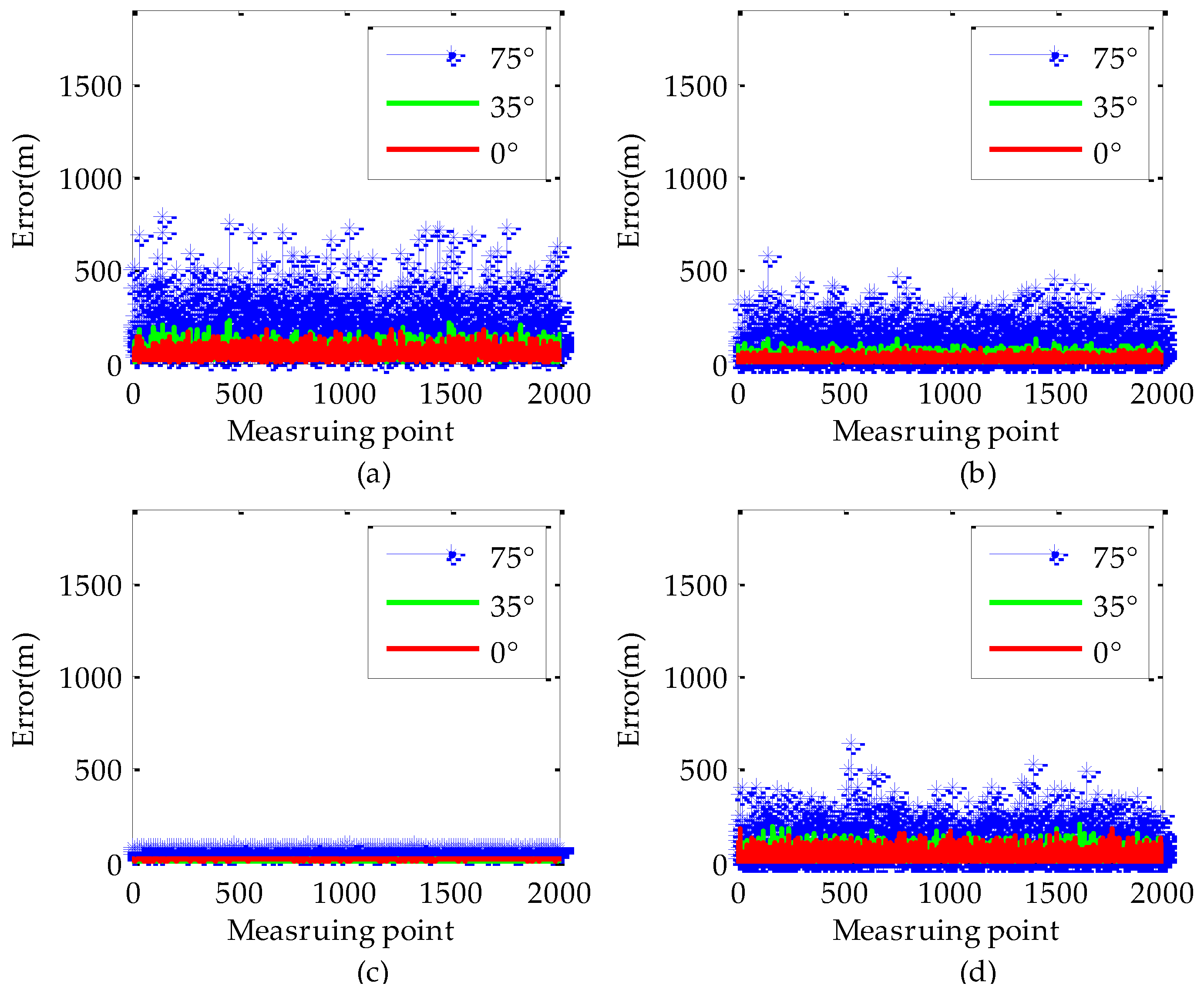
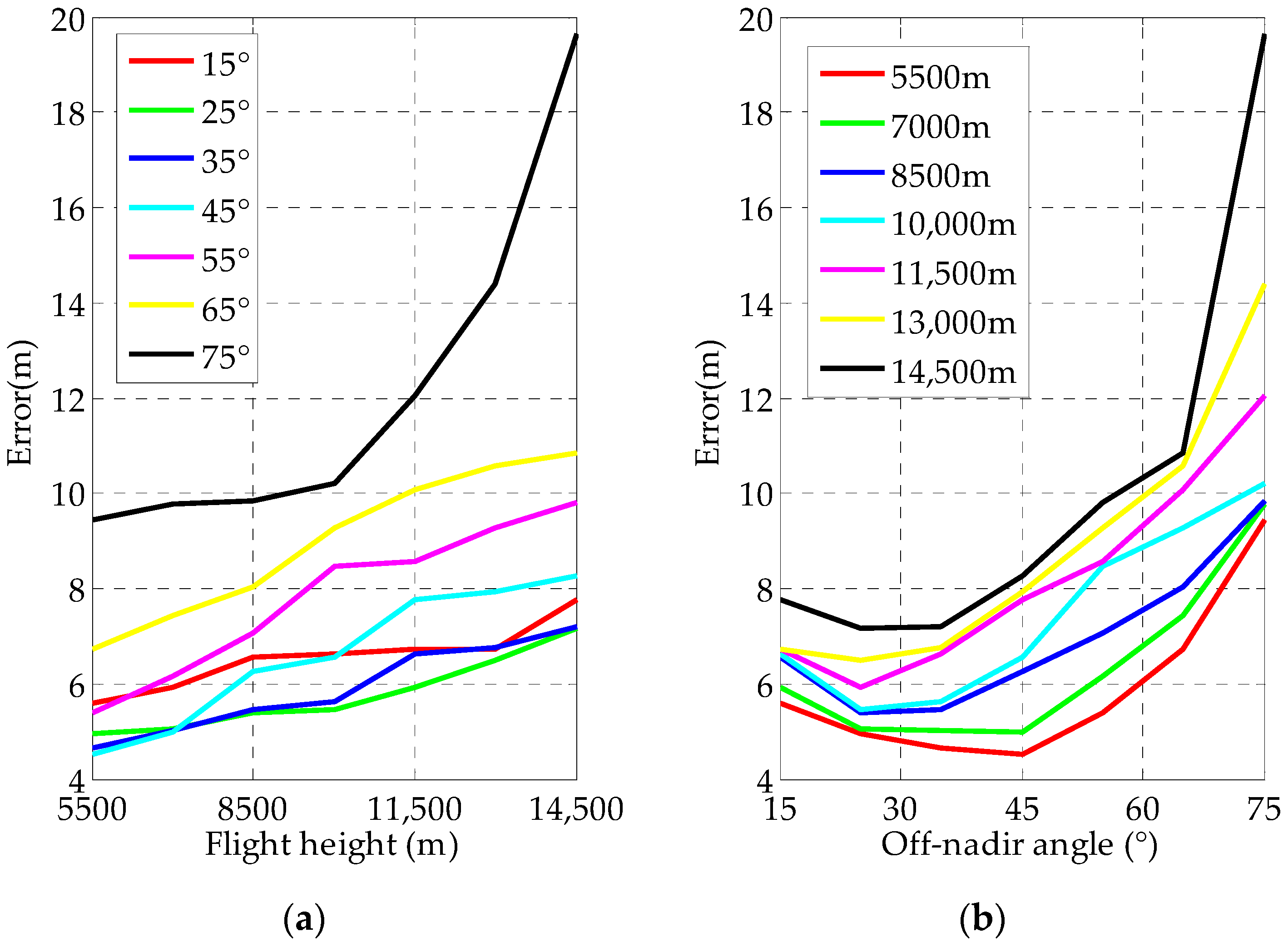
4.1.1. Effect of Flight Heights and Off-Nadir Looking Angle on Geo-Location Accuracy
- The geo-location accuracy is decreased with increasing flight height.
- The influence of the off-nadir looking angle on the geo-location accuracy is increased with the increment of the flight height.
- Even at a flight height of 14,500 m and an off-nadir looking angle of 75°, the target geo-location error is less than 20 m.
4.1.2. Effect of Target Elevation on Geo-Location Accuracy
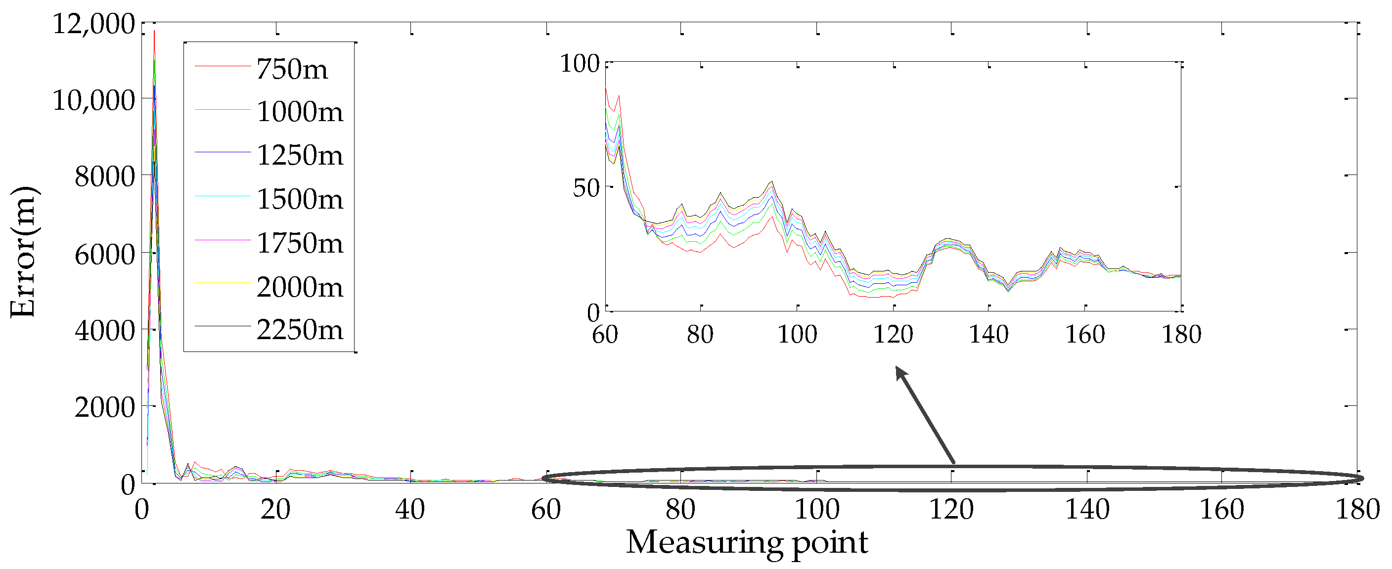
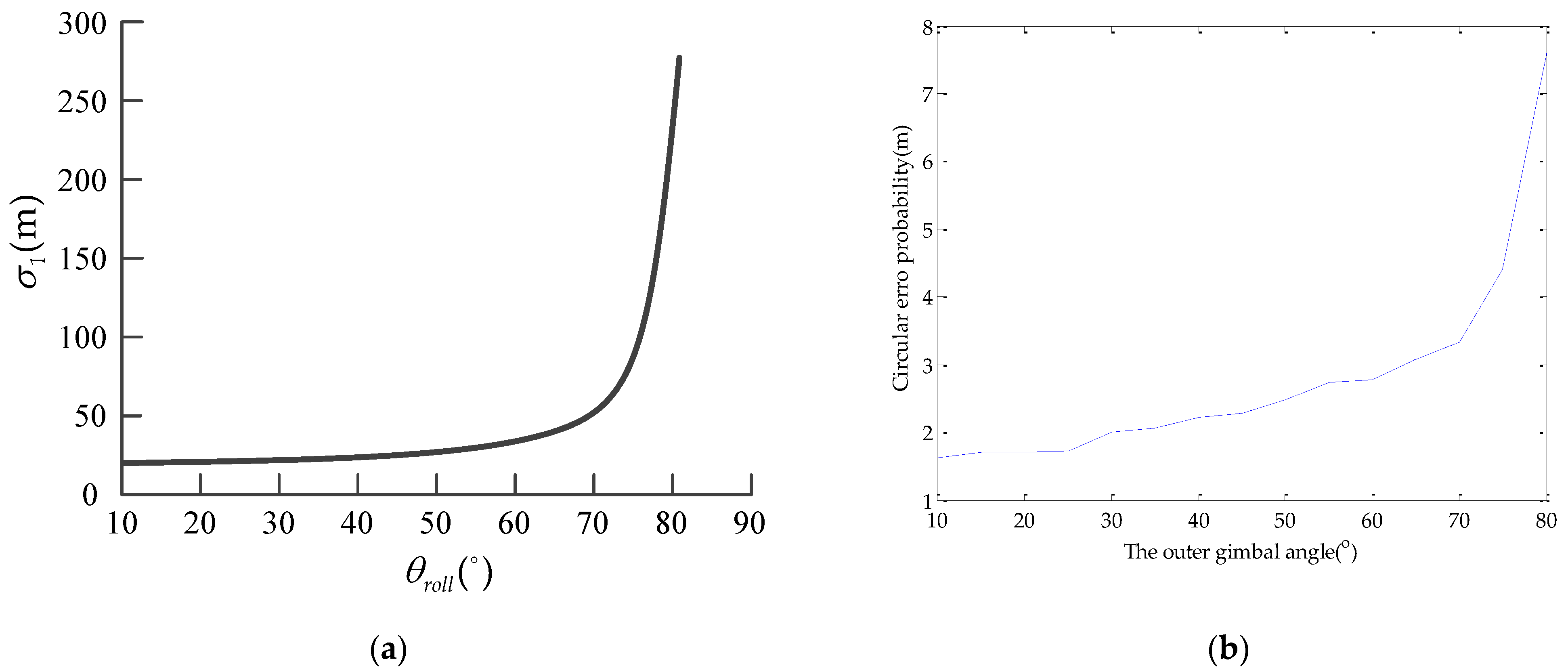
4.1.3. Effect of UAV Position and LOS Vector Direction on Geo-Location Accuracy
4.1.4. Comprehensive Simulation
4.1.5. Comparison of Simulation Experiment with the Traditional Method
4.1.6. Comparison of the Simulation Experiment with the DEM Method
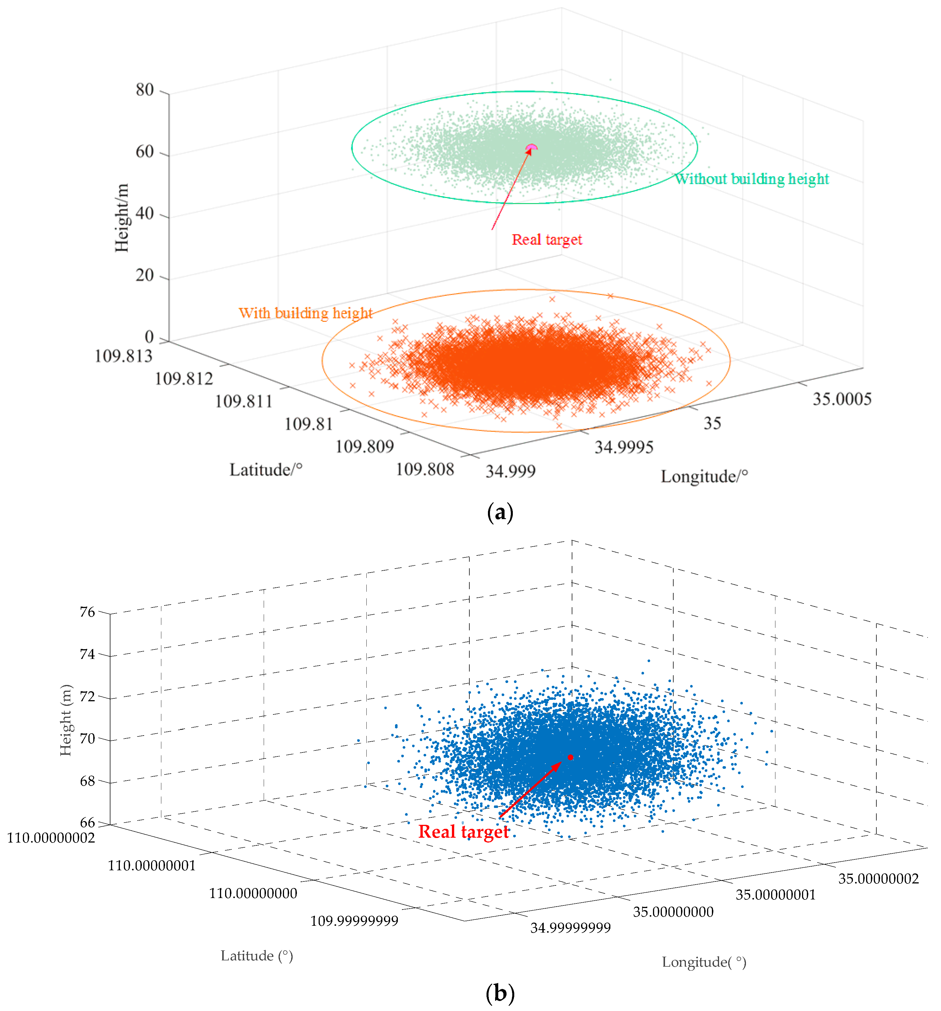
4.1.7. Comparison of the Simulation Experiment with the Building Target Geo-Location Method
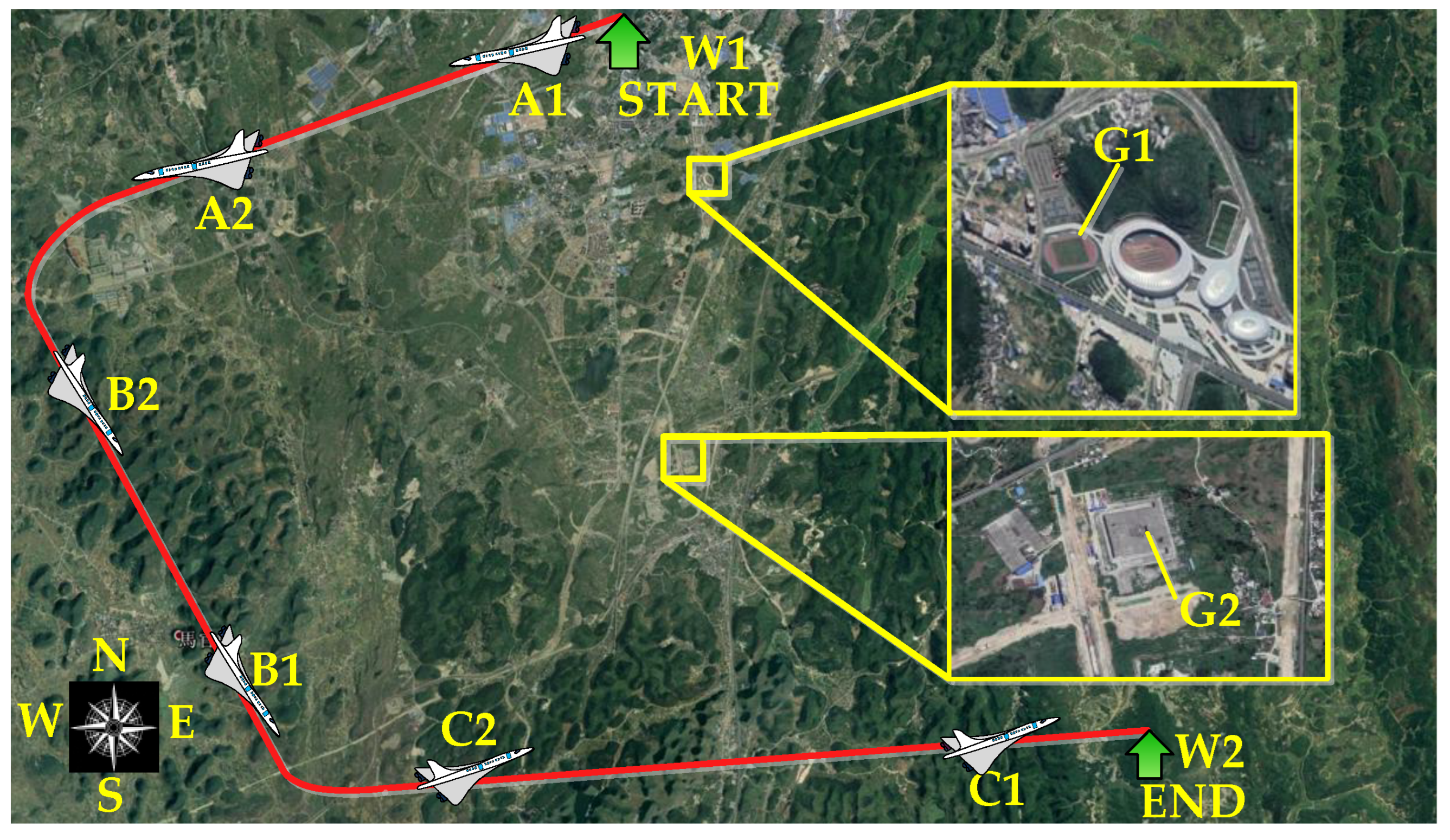
4.2. Flight Experiment and Results
5. Discussions
6. Conclusions
Author Contributions
Funding
Institutional Review Board Statement
Informed Consent Statement
Conflicts of Interest
Appendix A

References
- Iyengar, M.; Lange, D. The Goodrich 3rd generation DB-110 system: Operational on tactical and unmanned aircraft. Proc. SPIE 2006, 6209, 620909. [Google Scholar]
- Sohn, S.; Lee, B.; Kim, J.; Kee, C. Vision-based real-time target localization for single-antenna GPS-guided UAV. IEEE Trans. Aerosp. Electron. Syst. 2008, 44, 1391–1401. [Google Scholar] [CrossRef]
- Brownie, R.; Larroque, C. Night reconnaissance for F-16 multi-role reconnaissance pod. Proc. SPIE 2004, 5409, 1–7. [Google Scholar]
- Chai, R.; Savvaris, A.; Tsourdos, A.; Chai, S.; Xia, Y. Optimal tracking guidance for aeroassisted spacecraft reconnaissance mission based on receding horizon control. IEEE Trans. Aerosp. Electron. Syst. 2018, 54, 1575–1588. [Google Scholar] [CrossRef] [Green Version]
- Li, Y.; Zhang, W.; Li, P.; Ning, Y.; Suo, C. A method for autonomous navigation and positioning of UAV based on electric field array detection. Sensors 2021, 21, 1146. [Google Scholar] [CrossRef]
- Brown, S.; Lambrigtsen, B.; Denning, R.; Gaier, T.; Kangaslahti, P.; Lim, B.; Tanabe, J.; Tanner, A. The high-altitude MMIC sounding radiometer for the global hawk unmanned aerial vehicle: Instrument description and performance. IEEE Trans. Geosci. Remote Sens. 2011, 49, 3291–3301. [Google Scholar] [CrossRef]
- Popescu, D.; Stoican, F.; Stamatescu, G.; Ichim, L.; Dragana, C. Advanced UAV–WSN system for intelligent monitoring in precision agriculture. Sensors 2020, 20, 817. [Google Scholar] [CrossRef] [PubMed] [Green Version]
- Zheng, Q.; Huang, W.; Ye, H.; Dong, Y.; Shi, Y.; Chen, S. Using continous wavelet analysis for monitoring wheat yellow rust in different infestation stages based on unmanned aerial vehicle hyperspectral. Appl. Opt. 2020, 59, 8003–8013. [Google Scholar] [CrossRef] [PubMed]
- Wang, Y.; Yang, Y.; Kuang, H.; Yuan, D.; Yu, C.; Chen, J.; Huan, N.; Hou, H. High performance both in low-speed tracking and large-angle swing scanning based on adaptive nonsingular fast terminal sliding mode control for a three-axis universal inertially stabilized platform. Sensors 2020, 20, 5785. [Google Scholar] [CrossRef]
- Yuan, G.; Zheng, L.; Ding, Y.; Zhang, H.; Zhang, X.; Liu, X.; Sun, J. A precise calibration method for line scan cameras. IEEE Trans. Instrum. Meas. 2021, 70, 5013709. [Google Scholar] [CrossRef]
- Held, K.; Robinson, B. TIER II plus airborne EO sensor LOS control and image geolocation. In Proceedings of the IEEE Aerospace Conference, Snowmass, CO, USA, 13 February 1997; pp. 377–405. [Google Scholar]
- Sun, J.; Ding, Y.; Zhang, H.; Yuan, G.; Zheng, Y. Conceptual design and image motion compensation rate analysis of two-axis fast steering mirror for dynamic scan and stare imaging system. Sensors 2021, 21, 6441. [Google Scholar] [CrossRef] [PubMed]
- Yuan, G.; Zheng, L.; Sun, J.; Liu, X.; Wang, X.; Zhang, Z. Practical Calibration Method for Aerial Mapping Camera based on Multiple Pinhole Collimator. IEEE Access 2019, 8, 39725–39733. [Google Scholar] [CrossRef]
- Downs, J.; Prentice, R.; Dalzell, S.; Besachio, A.; Mansur, M. Control system development and flight test experience with the MQ-8B fire scout vertical take-Off unmanned aerial vehicle (VTUAV). In Annual Forum Proceedings-American Helicopter Society; American Helicopter Society, Inc.: Fairfax, VA, USA, 2007; pp. 566–592. [Google Scholar]
- Barber, D.; Redding, J.; McLain, T.; Beard, R.; Taylor, C. Vision-based target geolocation using a fixed-wing miniature air vehicle. J. Intell. Robot. Syst. 2006, 47, 361–382. [Google Scholar] [CrossRef]
- Stich, E. Geo-pointing and threat location techniques for airborne border surveillance. In Proceedings of the IEEE International Conference on Technologies for Homeland Security, Waltham, MA, USA, 12–14 November 2013; pp. 136–140. [Google Scholar]
- Du, Y.; Ding, Y.; Xu, Y.; Liu, Z.; Xiu, J. Geolocation algorithm for TDI-CCD aerial panoramic camera. Acta Opt. Sin. 2017, 37, 0328003. [Google Scholar]
- Zhang, H.; Qiao, C.; Kuang, H. Target-geo-location based on laser range finder for airborne electro-optical imaging systems. Opt. Precis. Eng. 2019, 27, 8–16. [Google Scholar] [CrossRef]
- Amann, M.; Bosch, T.; Lescure, M.; Myllyla, R.; Rioux, M. Laser ranging: A critical review of usual techniques for distance measurement. Opt. Eng. 2001, 40, 10–19. [Google Scholar]
- Qiao, C.; Ding, Y.; Xu, Y.; Ding, Y.; Xiu, J.; Du, Y. Ground target geo-location using imaging aerial camera with large inclined angles. Opt. Precis. Eng. 2017, 25, 1714–1726. [Google Scholar]
- Qiao, C.; Ding, Y.; Xu, Y.; Xiu, J. Ground target geolocation based on digital elevation model for airborne wide-area reconnaissance system. J. Appl. Remote Sens. 2018, 12, 016004. [Google Scholar] [CrossRef]
- Cai, Y.; Ding, Y.; Zhang, H.; Xiu, J.; Liu, Z. Geo-location algorithm for building target in oblique remote sensing images based on deep learning and height estimation. Remote Sens. 2020, 12, 2427. [Google Scholar] [CrossRef]
- Shiguemori, E.; Martins, M.; Monteiro, M. Landmarks recognition for autonomous aerial navigation by neural networks and Gabor transform. Proc. SPIE 2007, 6497, 64970R. [Google Scholar]
- Kumar, R.; Samarasekera, S.; Hsu, S.; Hanna, K. Registration of highly-oblique and zoomed in aerial video to reference imagery. In Proceedings of the 15th International Conference on Pattern Recognition(ICPR), Barcelona, Spain, 3–7 September 2000; pp. 303–307. [Google Scholar]
- Kumar, R.; Sawhney, H.; Asmuth, J.; Pope, A.; Hsu, S. Registration of video to geo-referenced imagery. In Proceedings of the 14th International Conference on Pattern Recognition(ICPR), Brisbane, QLD, Australia, 20 August 1998; pp. 1393–1400. [Google Scholar]
- Wang, Z.; Wang, H. Target Location of Loitering Munitions Based on Image Matching. In Proceedings of the IEEE Conference on Industrial Electronics and Applications, Beijing, China, 21–23 June 2011; pp. 606–609. [Google Scholar]
- Pack, D.; Toussaint, G. Cooperative control of UAVs for localization of intermittently emitting mobile targets. IEEE Trans. Syst. Man. Cybern 2009, 39, 959–970. [Google Scholar] [CrossRef] [PubMed]
- Lee, W.; Bang, H.; Leeghim, H. Cooperative localization between small UAVs using a combination of heterogeneous sensors. Aerosp. Sci. Technol 2013, 27, 105–111. [Google Scholar] [CrossRef]
- Bai, G.; Liu, J.; Song, Y.; Zuo, Y. Two-UAV intersection localization system based on the airborne optoelectronic platform. Sensors 2017, 17, 98. [Google Scholar] [CrossRef] [PubMed] [Green Version]
- Frew, E. Sensitivity of cooperative target geolocalization to orbit coordination. J. Guid. Control Dynam. 2008, 31, 1028–1040. [Google Scholar] [CrossRef]
- Ienkaran, A.; Simon, H. Cubature kalman filters. IEEE Trans. Automat. Contr. 2009, 54, 1254–1269. [Google Scholar]
- Zhang, Z.; Li, Q.; Han, L.; Dong, X.; Liang, Y.; Ren, Z. Consensus based strong tracking adaptive cubature kalman filtering for nonlinear system distributed estimation. IEEE Access 2019, 7, 98820–98831. [Google Scholar] [CrossRef]
- Kumar, P.; Da-Wei, G.; Ian, P. Square root cubature information filter. IEEE Sens. J. 2013, 13, 750–758. [Google Scholar]
- Mu, J.; Wang, C. Levenberg-marquardt method based iteration square root cubature kalman filter ant its applications. In Proceedings of the International Conference on Computer Network, Electronic and Automation, Xi’an, China, 23–25 September 2017; pp. 33–36. [Google Scholar]
- Helgesen, H.H.; Leira, F.S.; Johansen, T.A.; Fossen, T.I. Detection and Tracking of Floating Objects Using a UAV with Thermal Camera. In Sensing and Control for Autonomous Vehicles: Applications to Land, Water and Air Vehicles; Springer: Cham, Switzerland, 2017; pp. 289–316. [Google Scholar]
- Pan, H.; Tao, C.; Zou, Z. Precise georeferencing using the rigorous sensor model and rational function model for ZiYuan-3 strip scenes with minimum control. ISPRS J. Photogramm. Remote Sens. 2016, 119, 259–266. [Google Scholar] [CrossRef]
- Doneus, M.; Wieser, M.; Verhoeven, G.; Karel, W.; Fera, M.; Pfeifer, N. Automated Archiving of Archaeological Aerial Images. Remote Sens. 2016, 8, 209. [Google Scholar] [CrossRef] [Green Version]
- Jia, G.; Zhao, H.; Shang, H.; Lou, C.; Jiang, C. Pixel-size-varying method for simulation of remote sensing images. J. Appl. Remote Sens. 2014, 8, 083551. [Google Scholar] [CrossRef]


| Error Type | Error Value | |
|---|---|---|
| UAV position | latitude (north) | 0.00018° |
| longitude (east) | 0.00024° | |
| geodetic height (down) | 40 m | |
| UAV attitude | yaw | 0.3° |
| pitch | 0.1° | |
| roll | 0.1° | |
| gimbal angle | outer | 0.01° |
| inner | 0.01° |
| Method | Off-Nadir Looking Angle | The Geo-Location Error | |||
|---|---|---|---|---|---|
| UAV Position Error | LOS Vector Direction Error | Target Elevation Error | Total Error | ||
| The traditional method | 60° | 91 m | 24 m | 99 m | 151 m |
| 65° | 111 m | 30 m | 117 m | 182 m | |
| 70° | 141 m | 46 m | 147 m | 237 m | |
| 75° | 191 m | 69 m | 195 m | 316 m | |
| The proposed method | 60° | 2.36 m | 7.35 m | 0.73 m | 8.83 m |
| 65° | 2.45 m | 7.93 m | 0.76 m | 9.27 m | |
| 70° | 3.25 m | 8.26 m | 0.81 m | 9.98 m | |
| 75° | 4.3554 m | 9.52 m | 0.87 m | 10.44 m | |
| Error Type | Error Value | |
|---|---|---|
| UAV position | latitude (north) | 0.0001° |
| longitude (east) | 0.0001° | |
| geodetic height (down) | 5 m | |
| UAV attitude | yaw | 0.02° |
| pitch | 0.01° | |
| roll | 0.01° | |
| gimbal angle | outer | 0.006° |
| inner | 0.006° | |
| UAV flight | height | 18,000 m |
| Error Type | Error Value | |
|---|---|---|
| UAV position | latitude (north) | 0.0001° |
| longitude (east) | 0.0001° | |
| geodetic height (down) | 10 m | |
| UAV attitude | yaw | 0.06° |
| pitch | 0.02° | |
| roll | 0.02° | |
| gimbal angle | outer | 0.006° |
| inner | 0.006° | |
| UAV flight | height | 10,000 m |
| Method | The Average Position Error of the Latitude | The Average Position Error of the Longitude |
|---|---|---|
| The building target geo-location method [22] | 2.8738 × 10⁻⁶° | 2.3203 × 10⁻⁶° |
| The proposed method | 3.6398 × 10⁻⁹° | 4.3882 × 10⁻⁹° |
| Method | Error Type | Target Point G1 | Target Point G2 |
|---|---|---|---|
| Geographical position standard value by GNSS | latitude (north) | 26.221386° | 26.184767° |
| longitude (east) | 105.894206° | 105.857411° | |
| geodetic height (down) | 1367.89 m | 1324.67 m | |
| The proposed method | latitude (north) | 26.221087° | 26.184489° |
| longitude (east) | 105.894025° | 105.857283° | |
| geodetic height (down) | 1365.24 m | 1321.78 m | |
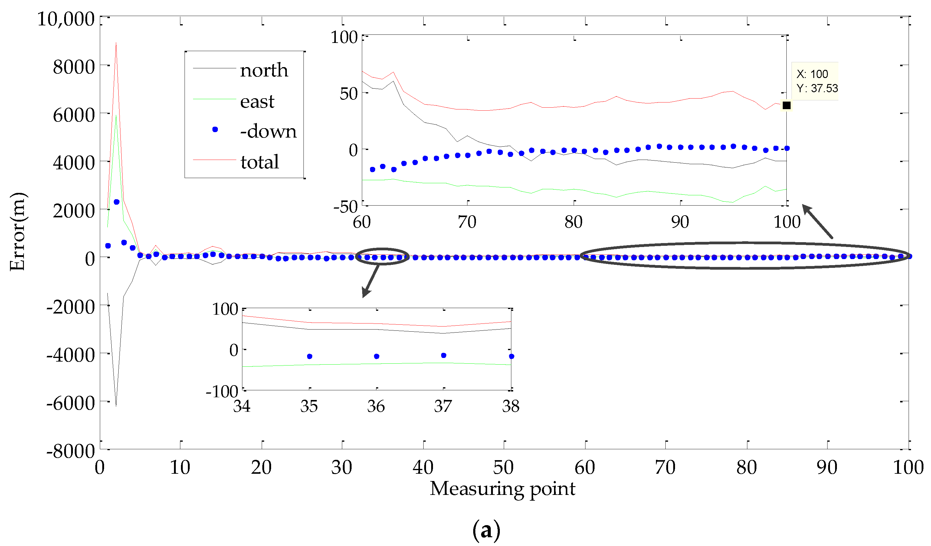
| total error | 37.53 m | 34.08 m | |
| The traditional method | latitude (north) | 26.2135937° | 26.1955568° |
| longitude (east) | 105.8838978° | 105.8639344° | |
| geodetic height (down) | 800 m | 800 m | |
| total error | 1459.3 m | 1459.5 m |
Publisher’s Note: MDPI stays neutral with regard to jurisdictional claims in published maps and institutional affiliations. |
© 2022 by the authors. Licensee MDPI, Basel, Switzerland. This article is an open access article distributed under the terms and conditions of the Creative Commons Attribution (CC BY) license (https://creativecommons.org/licenses/by/4.0/).
Share and Cite
Zhang, X.; Yuan, G.; Zhang, H.; Qiao, C.; Liu, Z.; Ding, Y.; Liu, C. Precise Target Geo-Location of Long-Range Oblique Reconnaissance System for UAVs. Sensors 2022, 22, 1903. https://doi.org/10.3390/s22051903
Zhang X, Yuan G, Zhang H, Qiao C, Liu Z, Ding Y, Liu C. Precise Target Geo-Location of Long-Range Oblique Reconnaissance System for UAVs. Sensors. 2022; 22(5):1903. https://doi.org/10.3390/s22051903
Chicago/Turabian StyleZhang, Xuefei, Guoqin Yuan, Hongwen Zhang, Chuan Qiao, Zhiming Liu, Yalin Ding, and Chongyang Liu. 2022. "Precise Target Geo-Location of Long-Range Oblique Reconnaissance System for UAVs" Sensors 22, no. 5: 1903. https://doi.org/10.3390/s22051903
APA StyleZhang, X., Yuan, G., Zhang, H., Qiao, C., Liu, Z., Ding, Y., & Liu, C. (2022). Precise Target Geo-Location of Long-Range Oblique Reconnaissance System for UAVs. Sensors, 22(5), 1903. https://doi.org/10.3390/s22051903