
Design and Development of an Autonomous Underwater Helicopter for Ecological Observation of Coral Reefs

 ,
,  and
and 
Abstract
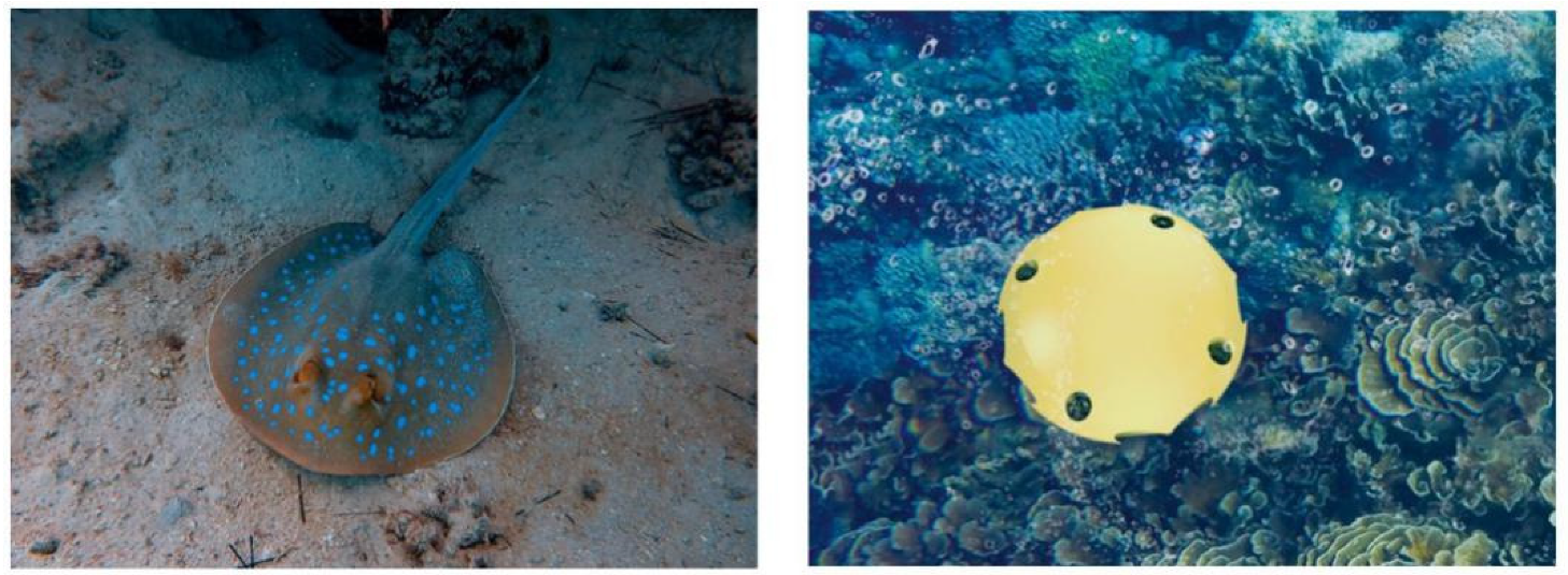
1. Introduction
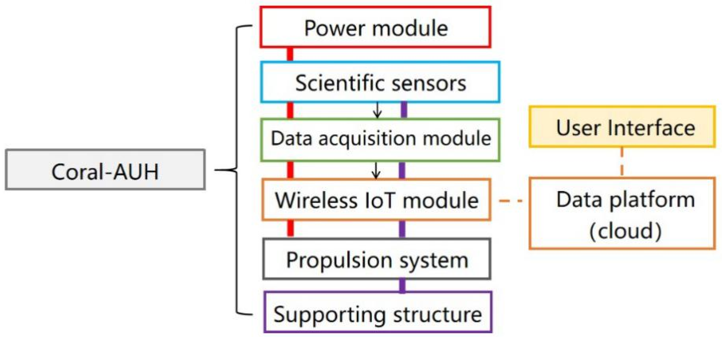
2. Configuration of Coral-AUH
2.1. System Architecture
2.2. Kinematic Modelling and Motion Analysis
2.3. CFD Simulation
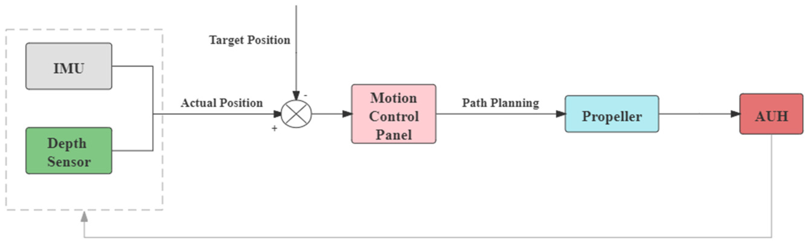
3. Guidance and Control Method
3.1. Guidance and Actuators
3.2. Motion Control
- (i)
- Forward and backward
- (ii)
- Up and down
- (iii)
- Left and right steering
3.3. Fuzzy-PID Control Algorithm
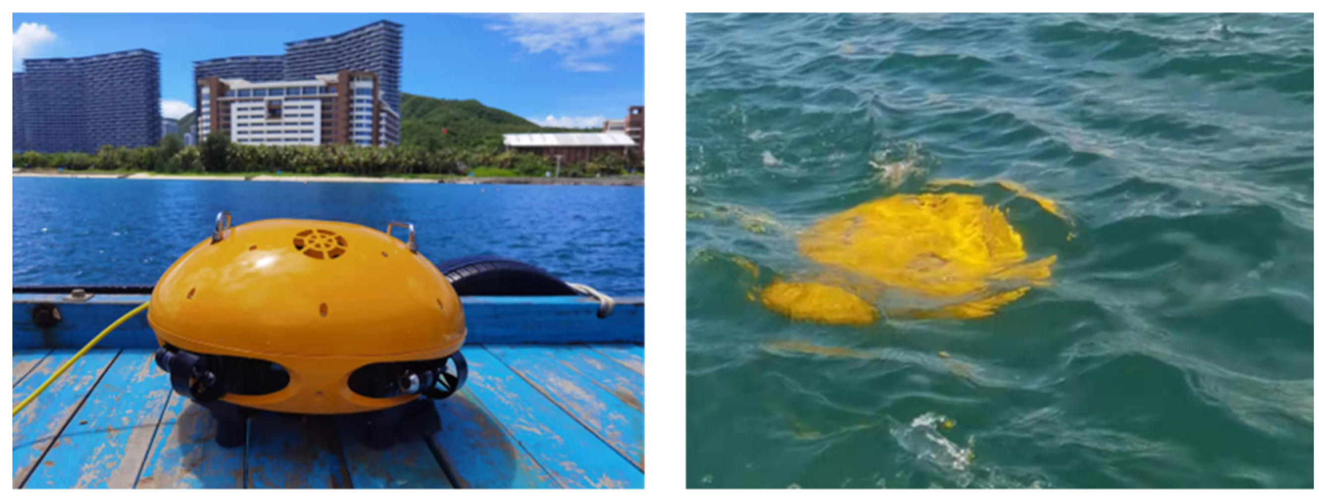
4. Field Test
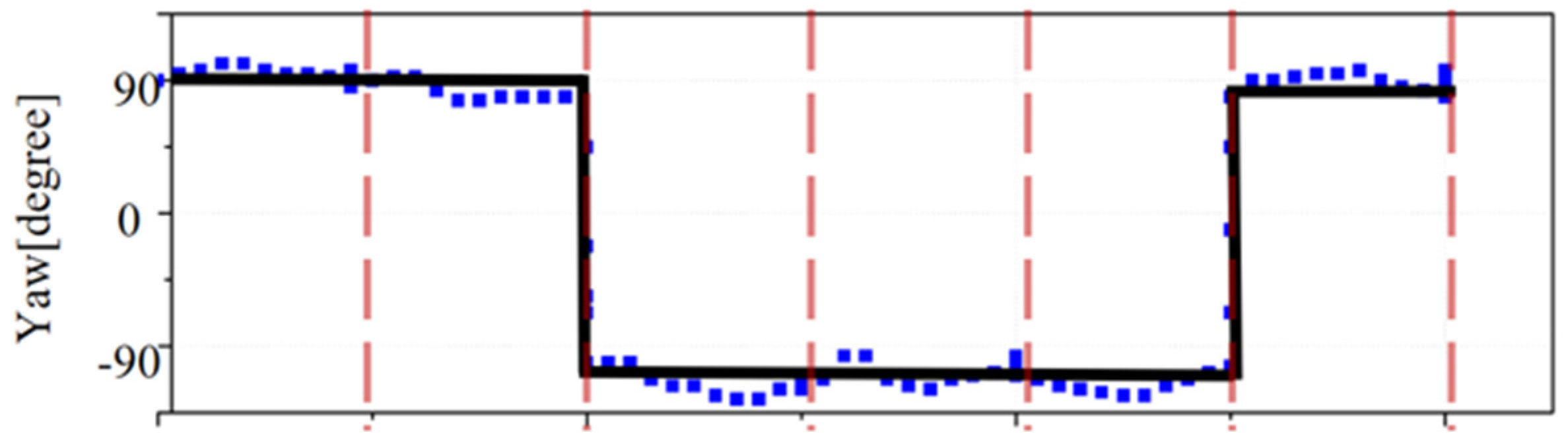
4.1. Motion Test
4.2. Field Test
5. Conclusions
Author Contributions
Funding
Institutional Review Board Statement
Informed Consent Statement
Data Availability Statement
Acknowledgments
Conflicts of Interest
References
- Burke, L.; Reytar, K.; Spalding, M.D. Reefs at risk revisited in the coral triangle. Ethics Med. 2011, 22, 2008–2010. [Google Scholar]
- Xing, X.; Wang, G.; Li, M.; Chen, Y.; Tian, T. Development of a comprehensive monitoring system on environmental information in sea ranching. J. Dalian Ocean. Univ. 2017, 32, 105–110. [Google Scholar]
- Xavier, H.; Madhumi, M.; Abhijit, N. Using remote sensing and remotely operated vehicles to improve ground-truthing efforts for underwater resources in a developing island nation. J. Appl. Remote Sens. 2013, 1, 1–8. [Google Scholar]
- Kilgour, M.J.; Auster, P.J.; Packer, D.; Purcell, M.; Packard, G.; Dessner, M.; Rissolo, D. Use of AUVs to inform management of deep-sea corals. Mar. Technol. Soc. J. 2014, 48, 21–27. [Google Scholar] [CrossRef]
- Morris, K.J.; Bett, B.J.; Durden, J.M.; Huvenne, V.A.; Milligan, R.; Jones, D.O.; Ruhl, H.A. A new method for ecological surveying of the abyss using autonomous underwater vehicle photography. Limnol. Oceanogr. Methods 2014, 12, 795–809. [Google Scholar] [CrossRef]
- Peng, W. The Research of Underwater Vehicle Used on Marine Ranching; Shanghai Ocean University: Shanghai, China, 2014. [Google Scholar]
- Berget, G.E.; Fossum, T.O.; Johansen, T.A.; Eidsvik, J.; Rajan, K. Adaptive Sampling of Ocean Processes Using an AUV with a Gaussian Proxy Model. IFAC-PapersOnLine 2018, 51, 238–243. [Google Scholar] [CrossRef]
- Wynn, R.B.; Huvenne, V.A.I.; Le Bas, T.P.; Murton, B.J.; Connelly, D.P.; Bett, B.J.; Ruhl, H.A.; Morris, K.J.; Peakall, J.; Parsons, D.R.; et al. Autonomous Underwater Vehicles (AUVs): Their past, present and future contributions to the advancement of marine geoscience. J. Mar. Geol. 2014, 352, 451–468. [Google Scholar] [CrossRef]
- Doya, C.; Chatzievangelou, D.; Bahamon, N.; Purser, A.; de Leo, F.C.; Juniper, S.K.; Thomsen, L.; Aguzzi, J. Seasonal monitoring of deep-sea megabenthos in Barkley Canyon cold seep by internet operated vehicle (IOV). PLoS ONE 2017, 12, e0176917. [Google Scholar] [CrossRef] [PubMed]
- Laschi, C.; Mazzolai, B.; Cianchetti, M. Soft robotics: Technologies and systems pushing the boundaries of robot abilities. Sci. Robot. 2016, 1, eaah3690. [Google Scholar] [CrossRef] [PubMed]
- Yoshida, H.; Aoki, T.; Osawa, H.; Ishibashi, S.; Watanabe, Y.; Tahara, J.; Miyazaki, T.; Itoh, K. A deepest depth ROV for sediment sampling and its sea trial result. In 2007 Symposium on Underwater Technology and Workshop on Scientific Use of Submaine Cables and Related Technologies; IEEE: Piscataway, NJ, USA, 2007; pp. 28–33. [Google Scholar]
- Chen, C.-W.; Jiang, Y.; Huang, H.-C.; Ji, D.-X.; Sun, G.-Q.; Yu, Z.; Chen, Y. Computational fluid dynamics study of the motion stability of an autonomous underwater helicopter. Ocean Eng. 2017, 143, 227–239. [Google Scholar] [CrossRef]
- Feng, Z.; Chen, C.-W.; Yu, Z.; Huang, H.-C.; Su, H.; Leng, J.-X.; Chen, Y. Hydrodynamic Performance Analysis of Underwater Helicopter Based on STAR-CCM+. In OCEANS-MTS; IEEE: Piscataway, NJ, USA, 2018. [Google Scholar]
- Cai, Q.-W.; Chen, C.-W.; Yu, Z.; Huang, H.-C.; Yan, N.-M.; Su, H.; Leng, J.-X.; Chen, Y. Numerical Analysis of Hydrodynamic Interaction for AUH and Mother Ship in Different Regular Wave Directions. In OCEANS-MTS; IEEE: Piscataway, NJ, USA, 2018. [Google Scholar]
- Chen, C.-W.; Yan, N.-M. Prediction of added mass for an autonomous underwater vehicle moving near sea bottom using panel method. In Proceedings of the 4th International Conference on Information Science and Control Engineering (ICISCE 2017), Changsha, China, 21–23 July 2017; pp. 1094–1098. [Google Scholar]
- Chen, C.; Yan, N.; Leng, J.; Chen, Y. Numerical analysis of second-order wave forces acting on an autonomous underwater helicopter using panel method. In OCEANS-MTS; IEEE: Piscataway, NJ, USA, 2017. [Google Scholar]
- Wang, Z.; Liu, X.; Huang, H.; Chen, Y. Development of an underwater autonomous helicopter with high maneuverability. Appl. Sci. 2019, 9, 4072. [Google Scholar] [CrossRef]
- Ji, D.; Chen, C.; Chen, Y. Autonomous Underwater Helicopters, AUV with Disc-shaped Design for Deepwater Agility. Sea Technol. 2018, 59, 25–27. [Google Scholar]
- Jiang, X. Unmanned Underwater Vehicles; Liaoning Science and Techinology Publishing House: Shenyang, China, 2000; pp. 244–248. [Google Scholar]
- Titterton, D.; Weston, J.L.; Weston, J. Strapdown Inertial Navigation Technology, 2nd ed.; The Institution of Engineering and Technology: London, UK, 2004; p. 574. [Google Scholar]
- Yakhot, V.; Orszag, S.A. Renormalization-Group Analysis of Turbulence. Phys. Rev. Lett. 1986, 57, 1722–1724. [Google Scholar] [CrossRef] [PubMed]


| Parameter | Displacement | Position Angle |
|---|---|---|
| Vector | Speed (V) | Angular Velocity (Ω) | Force (F) | Torque (M) |
|---|---|---|---|---|
| x | u | p | X | K |
| y | v | q | Y | M |
| z | w | r | Z | N |
| Position | pH | Electric Conductivity (uS/cm) | Dissolved Oxygen Concentration (mg/L) | Turbidity (FTU) | Chlorophyll (ug/L) | |
|---|---|---|---|---|---|---|
| Eastern Longitude | Northern Latitude | |||||
| 18°12′42′’ | 109°28′21” | 8.08 | 47.8 | 6.32 | 21.05 | 3.02 |
| 18°12′45′’ | 109°28′25′’ | 8.13 | 46.35 | 6.17 | 19.83 | 3 |
| 18°12′46′’ | 109°28′34” | 8.11 | 47.48 | 5.93 | 23.42 | 2.72 |
| 18°12′47” | 109°28′38” | 8.13 | 52.64 | 5.89 | 16.8 | 3.39 |
| Position | pH | Electric Conductivity (uS/cm) | Dissolved Oxygen Concentration (mg/L) | Turbidity (FTU) | Chlorophyll (ug/L) | |
|---|---|---|---|---|---|---|
| Eastern Longitude | Northern Latitude | |||||
| 18°19′32′’ | 108°59′30′’ | 8.06 | 47.8 | 5.99 | 20.21 | 3.2 |
| 18°19′28′’ | 108°59′20′’ | 8.15 | 46.35 | 6.03 | 35.02 | 4.81 |
| 18°19′42′’ | 108°59′18′’ | 8.2 | 47.48 | 6.01 | 15.98 | 2.91 |
| 18°19′44′’ | 108°59′19′’ | 8.25 | 52.64 | 5.91 | 16.13 | 3.23 |
Publisher’s Note: MDPI stays neutral with regard to jurisdictional claims in published maps and institutional affiliations. |
© 2022 by the authors. Licensee MDPI, Basel, Switzerland. This article is an open access article distributed under the terms and conditions of the Creative Commons Attribution (CC BY) license (https://creativecommons.org/licenses/by/4.0/).
Share and Cite
Zhou, J.; Zhou, N.; Che, Y.; Gao, J.; Zhao, L.; Huang, H.; Chen, Y. Design and Development of an Autonomous Underwater Helicopter for Ecological Observation of Coral Reefs. Sensors 2022, 22, 1770. https://doi.org/10.3390/s22051770
Zhou J, Zhou N, Che Y, Gao J, Zhao L, Huang H, Chen Y. Design and Development of an Autonomous Underwater Helicopter for Ecological Observation of Coral Reefs. Sensors. 2022; 22(5):1770. https://doi.org/10.3390/s22051770
Chicago/Turabian StyleZhou, Jing, Nanxi Zhou, Yuchao Che, Jian Gao, Liming Zhao, Haocai Huang, and Ying Chen. 2022. "Design and Development of an Autonomous Underwater Helicopter for Ecological Observation of Coral Reefs" Sensors 22, no. 5: 1770. https://doi.org/10.3390/s22051770
APA StyleZhou, J., Zhou, N., Che, Y., Gao, J., Zhao, L., Huang, H., & Chen, Y. (2022). Design and Development of an Autonomous Underwater Helicopter for Ecological Observation of Coral Reefs. Sensors, 22(5), 1770. https://doi.org/10.3390/s22051770