
A Cylindrical Grip Type of Tactile Device Using Magneto-Responsive Materials Integrated with Surgical Robot Console: Design and Analysis


Abstract
:1. Introduction
1.1. Literature Review
1.2. Proposed Design Methodology
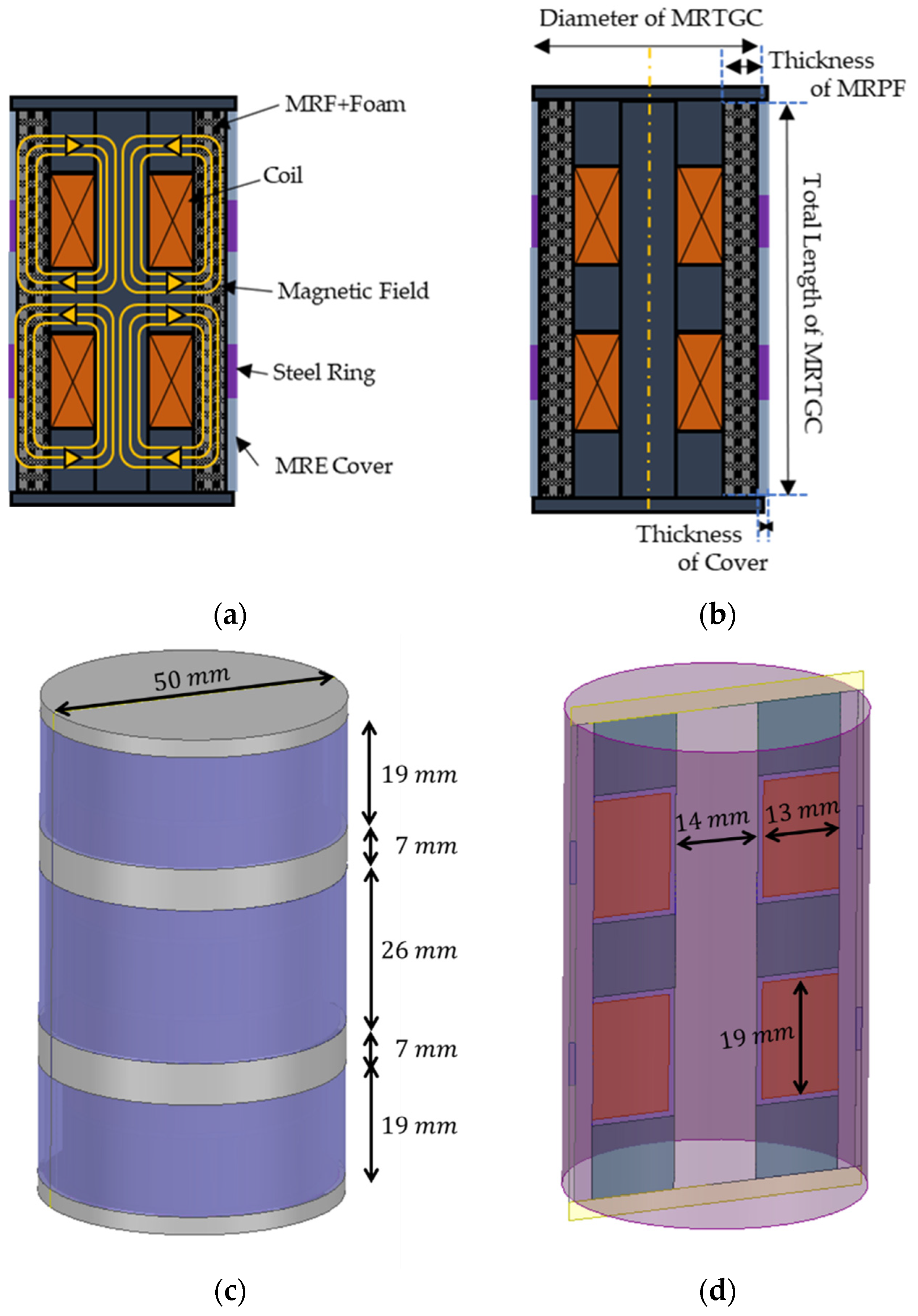
2. Design Concept of MRTGC
3. Characteristics of Magnetic-Responsive Materials
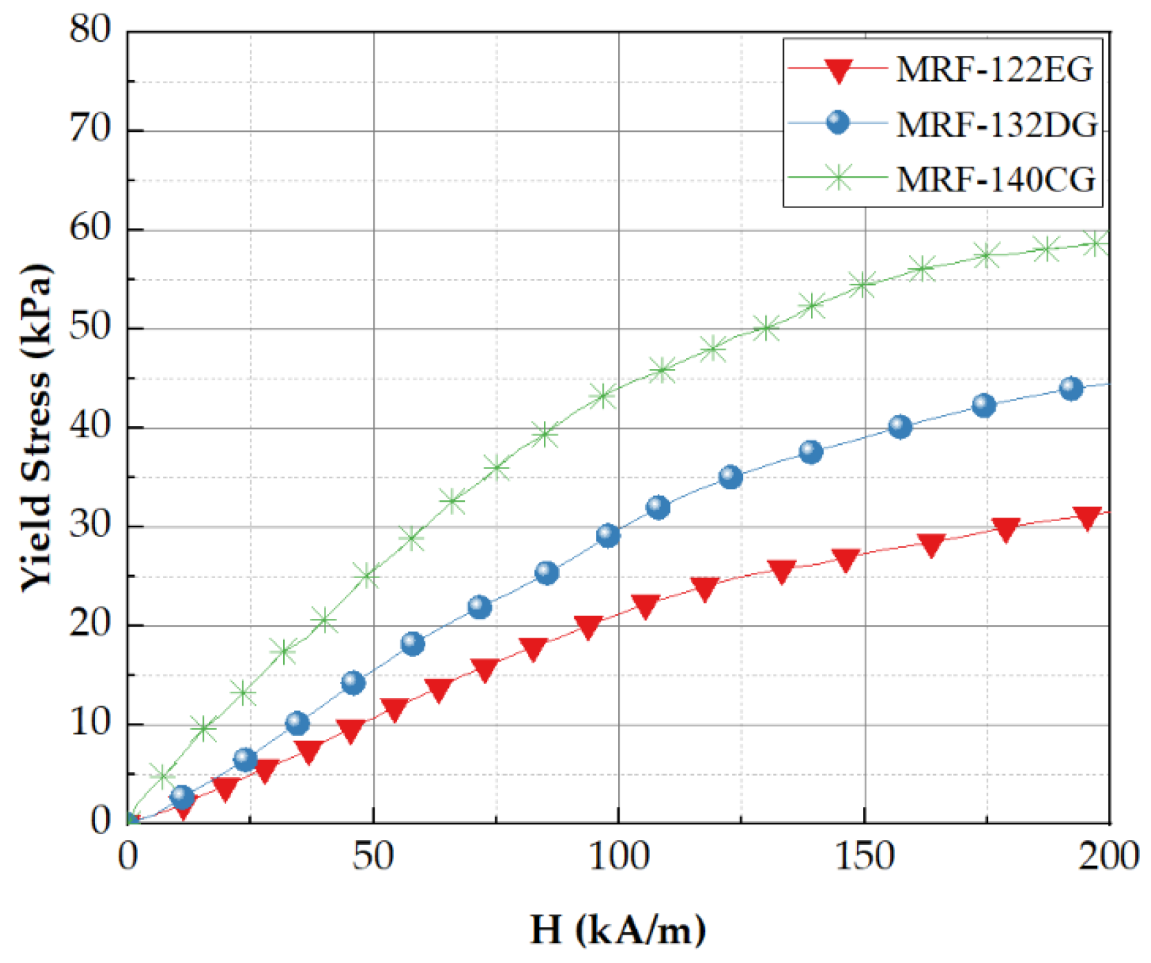
3.1. Magnetorheological Fluid
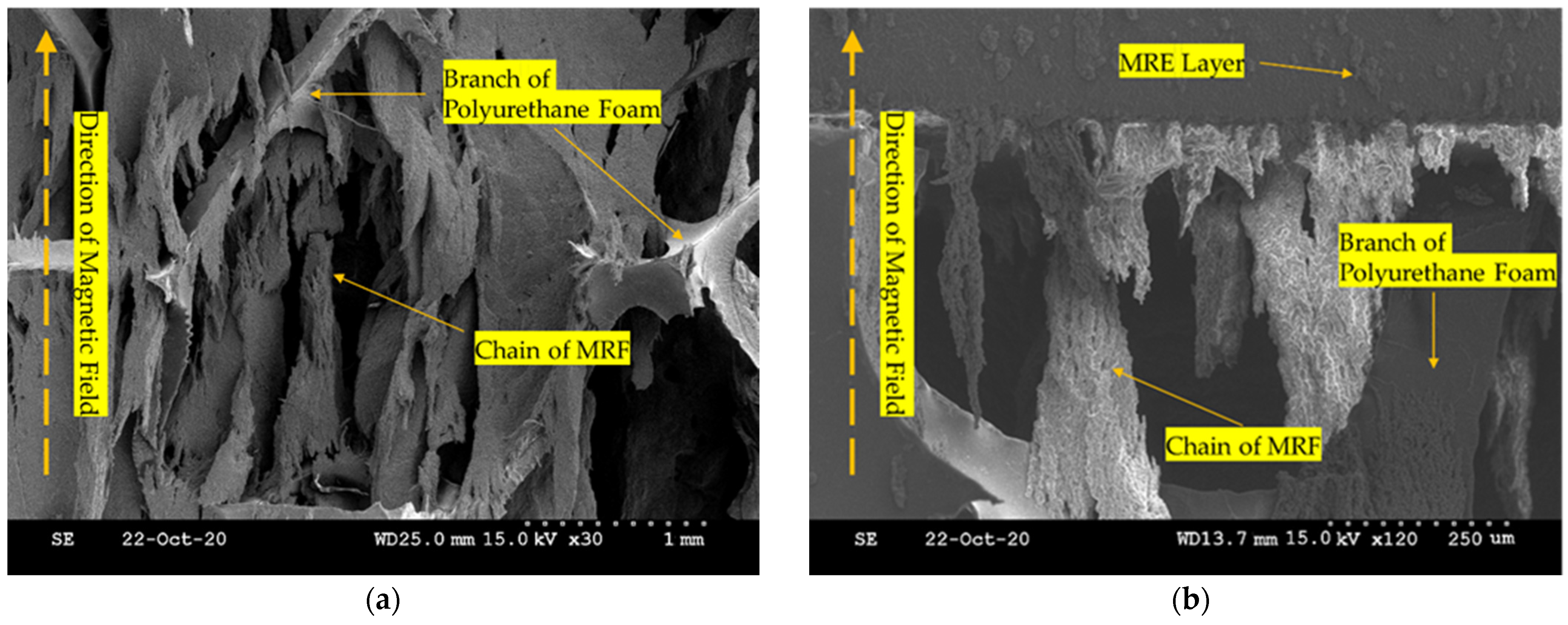
3.2. Magnetorheological Elastomer and Polyurethane Foam
4. Yield Stress Analysis of MRTGC
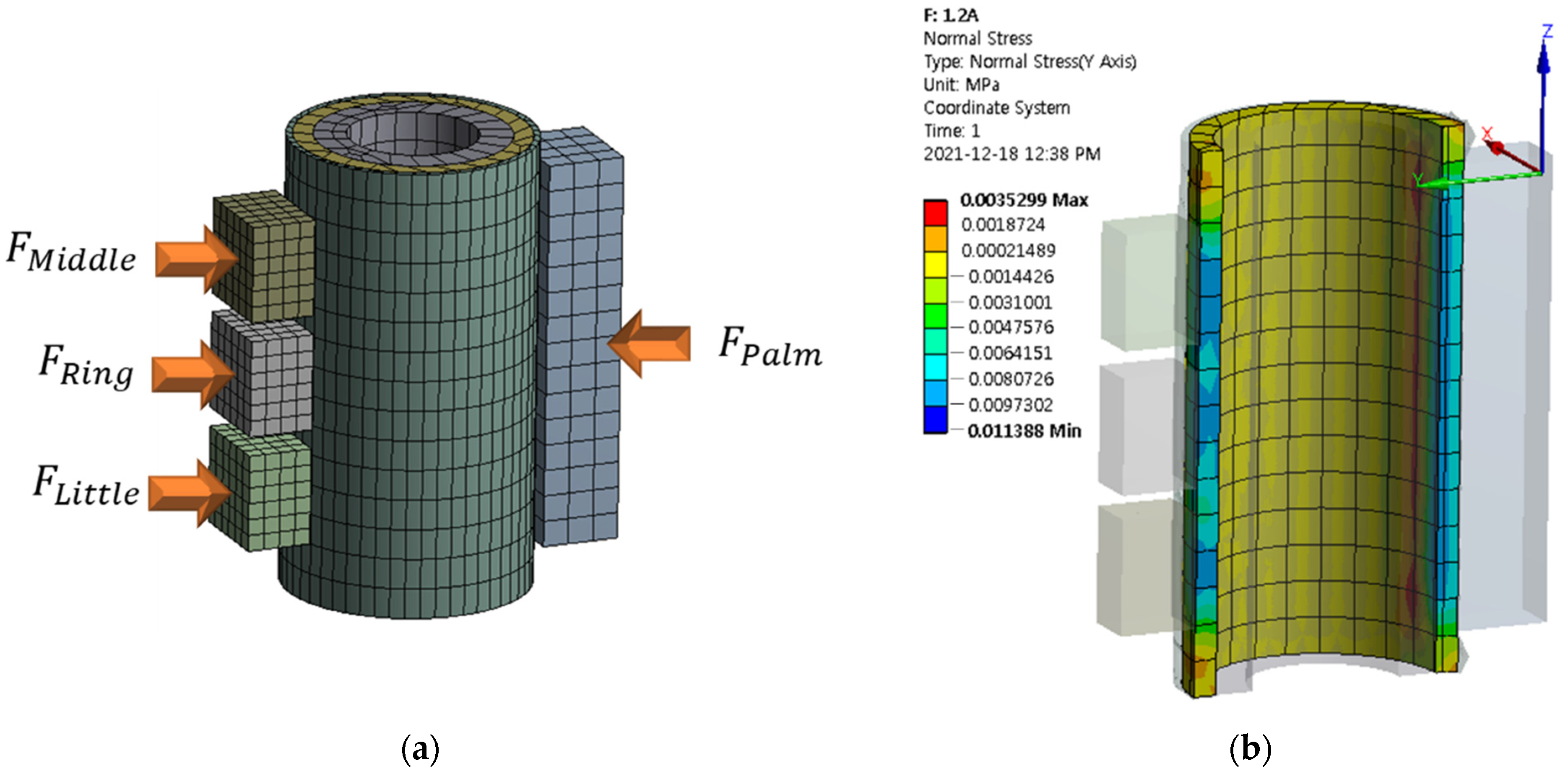
5. Stiffness Analysis
6. Conclusions
Author Contributions
Funding
Institutional Review Board Statement
Informed Consent Statement
Data Availability Statement
Conflicts of Interest
References
- Schostek, S.; Schurr, M.O.; Buess, G.F. Review on aspects of artificial tactile feedback in laparoscopic surgery. Med. Eng. Phys. 2009, 31, 887–898. [Google Scholar] [CrossRef] [PubMed]
- Naitoh, T.; Gagner, M.; Garcia-Ruiz, A.; Heniford, B.; Ise, H.; Matsuno, S. Hand-assisted laparoscopic digestive surgery provides safety and tactile sensation for malignancy or obesity. Surg. Endosc. 1999, 13, 157–160. [Google Scholar] [CrossRef] [PubMed]
- Schostek, S.; Ho, C.N.; Kalanovic, D.; Schurr, M.O. Artificial tactile sensing in minimally invasive surgery—A new technical approach. Minim. Invasive Ther. Allied Technol. 2006, 15, 296–304. [Google Scholar] [CrossRef] [PubMed]
- Kraft, B.; Jäger, C.; Kraft, K.; Leibl, B.; Bittner, R. The AESOP robot system in laparoscopic surgery: Increased risk or advantage for surgeon and patient? Surg. Endosc. Other Interv. Tech. 2004, 18, 1216–1223. [Google Scholar] [CrossRef] [PubMed]
- Troisi, R.I.; Patriti, A.; Montalti, R.; Casciola, L. Robot assistance in liver surgery: A real advantage over a fully laparoscopic approach? Results of a comparative bi-institutional analysis. Int. J. Med. Robot. Comput. Assist. Surg. 2013, 9, 160–166. [Google Scholar] [CrossRef]
- Dupont, P.E.; Nelson, B.J.; Goldfarb, M.; Hannaford, B.; Menciassi, A.; O’Malley, M.K.; Simaan, N.; Valdastri, P.; Yang, G.Z. A decade retrospective of medical robotics research from 2010 to 2020. Sci. Robot. 2021, 6, eabi8017. [Google Scholar] [CrossRef]
- Fuchs, K. Minimally invasive surgery. Endoscopy 2002, 34, 154–159. [Google Scholar] [CrossRef]
- Robinson, T.; Stiegmann, G. Minimally invasive surgery. Endoscopy 2004, 36, 48–51. [Google Scholar] [PubMed]
- McDonald, G.J. Design and Modeling of Millimeter-Scale Soft Robots for Medical Applications. Ph.D. Thesis, University of Minnesota, Minneapolis, MN, USA, 2021. [Google Scholar]
- Currò, G.; La Malfa, G.; Caizzone, A.; Rampulla, V.; Navarra, G. Three-dimensional (3D) versus two-dimensional (2D) laparoscopic bariatric surgery: A single-surgeon prospective randomized comparative study. Obes. Surg. 2015, 25, 2120–2124. [Google Scholar] [CrossRef] [PubMed]
- Dogangil, G.; Davies, B.; Rodriguez y Baena, F. A review of medical robotics for minimally invasive soft tissue surgery. Proc. Inst. Mech. Eng. Part H J. Eng. Med. 2010, 224, 653–679. [Google Scholar] [CrossRef]
- Yu, L.; Wang, Z.; Yu, P.; Wang, T.; Song, H.; Du, Z. A new kinematics method based on a dynamic visual window for a surgical robot. Robotica 2014, 32, 571–589. [Google Scholar] [CrossRef]
- Okamura, A.M. Haptics in robot-assisted minimally invasive surgery. In the Encyclopedia of Medical Robotics; Minimally Invasive Surgical Robotics; World Scientific: Singapore, 2019; Volume 1, pp. 317–339. [Google Scholar] [CrossRef]
- Byrn, J.C.; Schluender, S.; Divino, C.M.; Conrad, J.; Gurland, B.; Shlasko, E.; Szold, A. Three-dimensional imaging improves surgical performance for both novice and experienced operators using the da Vinci Robot System. Am. J. Surg. 2007, 193, 519–522. [Google Scholar] [CrossRef] [PubMed]
- Kim, S.; Chung, J.; Yi, B.-J.; Kim, Y.S. An assistive image-guided surgical robot system using O-arm fluoroscopy for pedicle screw insertion: Preliminary and cadaveric study. Neurosurgery 2010, 67, 1757–1767. [Google Scholar] [CrossRef] [PubMed] [Green Version]
- Nagy, T.D.; Haidegger, T. A dvrk-based framework for surgical subtask automation. Acta Polytech. Hung. 2019, 16, 61–78. [Google Scholar]
- Millan, B.; Nagpal, S.; Ding, M.; Lee, J.Y.; Kapoor, A. A Scoping Review of Emerging and Established Surgical Robotic Platforms With Applications in Urologic Surgery. Société Int. D’urologie J. 2021, 2, 300–310. [Google Scholar] [CrossRef]
- Nagyné Elek, R.; Haidegger, T. Robot-assisted minimally invasive surgical skill assessment—Manual and automated platforms. Acta Polytech. Hung. 2019, 16, 141–169. [Google Scholar]
- Bark, K.; McMahan, W.; Remington, A.; Gewirtz, J.; Wedmid, A.; Lee, D.I.; Kuchenbecker, K.J. In vivo validation of a system for haptic feedback of tool vibrations in robotic surgery. Surg. Endosc. 2013, 27, 656–664. [Google Scholar] [CrossRef]
- Van der Meijden, O.A.; Schijven, M.P. The value of haptic feedback in conventional and robot-assisted minimal invasive surgery and virtual reality training: A current review. Surg. Endosc. 2009, 23, 1180–1190. [Google Scholar] [CrossRef] [Green Version]
- Bethea, B.T.; Okamura, A.M.; Kitagawa, M.; Fitton, T.P.; Cattaneo, S.M.; Gott, V.L.; Baumgartner, W.A.; Yuh, D.D. Application of haptic feedback to robotic surgery. J. Laparoendosc. Adv. Surg. Tech. 2004, 14, 191–195. [Google Scholar] [CrossRef]
- Amirabdollahian, F.; Livatino, S.; Vahedi, B.; Gudipati, R.; Sheen, P.; Gawrie-Mohan, S.; Vasdev, N. Prevalence of haptic feedback in robot-mediated surgery: A systematic review of literature. J. Robot. Surg. 2018, 12, 11–25. [Google Scholar] [CrossRef] [Green Version]
- Okamura, A.M. Haptic feedback in robot-assisted minimally invasive surgery. Curr. Opin. Urol. 2009, 19, 102. [Google Scholar] [CrossRef] [PubMed]
- Okamura, A.M. Methods for haptic feedback in teleoperated robot-assisted surgery. Ind. Robot. Int. J. 2004, 31, 499–508. [Google Scholar] [CrossRef] [PubMed] [Green Version]
- Pacchierotti, C.; Scheggi, S.; Prattichizzo, D.; Misra, S. Haptic feedback for microrobotics applications: A review. Front. Robot. AI 2016, 3, 53. [Google Scholar] [CrossRef] [Green Version]
- Yeh, C.-H.; Su, F.-C.; Shan, Y.-S.; Dosaev, M.; Selyutskiy, Y.; Goryacheva, I.; Ju, M.-S. Application of piezoelectric actuator to simplified haptic feedback system. Sens. Actuators A Phys. 2020, 303, 111820. [Google Scholar] [CrossRef]
- Okamura, A.M.; Dennerlein, J.T.; Howe, R.D. Vibration feedback models for virtual environments. In Proceedings of the 1998 IEEE International Conference on Robotics and Automation (Cat. No. 98CH36146), Leuven, Belgium, 20 May 1998; Volume 1, pp. 674–679. [Google Scholar] [CrossRef]
- Luostarinen, L.O.; Åman, R.; Handroos, H. Haptic joystick for improving controllability of remote-operated hydraulic mobile machinery. In Fluid Power Systems Technology, Proceedings of the 9th FPNI Ph.D. Symposium on Fluid Power, Florianópolis, SC, Brazil, 26–28 October 2016; American Society of Mechanical Engineers: New York, NY, USA, 2016; Volume 50473, p. 00101003. [Google Scholar] [CrossRef]
- Shang, W.; Su, H.; Li, G.; Fischer, G.S. Teleoperation system with hybrid pneumatic-piezoelectric actuation for MRI-guided needle insertion with haptic feedback. In Proceedings of the 2013 IEEE/RSJ International Conference on Intelligent Robots and Systems, Tokyo, Japan, 3–7 November 2013; pp. 4092–4098. [Google Scholar] [CrossRef] [Green Version]
- Kim, P.; Kim, S.; Park, Y.-D.; Choi, S.-B. Force modeling for incisions into various tissues with MRF haptic master. Smart Mater. Struct. 2016, 25, 035008. [Google Scholar] [CrossRef]
- Hooshiar, A.; Payami, A.; Dargahi, J.; Najarian, S. Magnetostriction-based force feedback for robot-assisted cardiovascular surgery using smart magnetorheological elastomers. Mech. Syst. Signal Processing 2021, 161, 107918. [Google Scholar] [CrossRef]
- Shokrollahi, E.; Goldenberg, A.A.; Drake, J.M.; Eastwood, K.W.; Kang, M. Application of a nonlinear Hammerstein-Wiener estimator in the development and control of a magnetorheological fluid haptic device for robotic bone biopsy. Actuators 2018, 7, 83. [Google Scholar] [CrossRef] [Green Version]
- Najmaei, N.; Asadian, A.; Kermani, M.R.; Patel, R.V. Design and performance evaluation of a prototype MRF-based haptic interface for medical applications. IEEE/ASME Trans. Mechatron. 2015, 21, 110–121. [Google Scholar] [CrossRef]
- Song, Y.; Guo, S.; Yin, X.; Zhang, L.; Wang, Y.; Hirata, H.; Ishihara, H. Design and performance evaluation of a haptic interface based on MR fluids for endovascular tele-surgery. Microsyst. Technol. 2018, 24, 909–918. [Google Scholar] [CrossRef]
- Kikuchi, T.; Takano, T.; Yamaguchi, A.; Ikeda, A.; Abe, I. Haptic Interface with Twin-Driven MR Fluid Actuator for Teleoperation Endoscopic Surgery System. Actuators 2021, 10, 245. [Google Scholar] [CrossRef]
- Najmaei, N.; Asadian, A.; Kermani, M.R.; Patel, R.V. Performance evaluation of Magneto-Rheological based actuation for haptic feedback in medical applications. In Proceedings of the 2015 IEEE/RSJ International Conference on Intelligent Robots and Systems (IROS), Hamburg, Germany, 28 September–2 October 2015; pp. 573–578. [Google Scholar] [CrossRef]
- Gao, Q.; Zhan, Y.; Song, Y.; Liu, J.; Wu, J. An MR Fluid based Master Manipulator of the Vascular Intervention Robot with Haptic Feedback. In Proceedings of the 2021 IEEE International Conference on Mechatronics and Automation (ICMA), Takamatsu, Japan, 8–11 August 2021; pp. 158–163. [Google Scholar] [CrossRef]
- Nguyen, N.D.; Truong, T.D.; Nguyen, D.H.; Nguyen, Q.H. Development of a 3D haptic spherical master manipulator based on MRF actuators. In Active and Passive Smart Structures and Integrated Systems XIII International Society for Optics and Photonics, Proceedings of the SPIE Smart Structures + Nondestructive Evaluation, Denver, CO, USA, 3–7 March 2019; SPIE: Bellingham, WA, USA; Volume 10967, p. 109671. [CrossRef]
- Kim, S.; Kim, P.; Park, C.-Y.; Choi, S.-B. A new tactile device using magneto-rheological sponge cells for medical applications: Experimental investigation. Sens. Actuators A Phys. 2016, 239, 61–69. [Google Scholar] [CrossRef]
- Cha, S.-W.; Kang, S.-R.; Hwang, Y.-H.; Choi, S.-B. A single of MR sponge tactile sensor design for medical applications. In Active and Passive Smart Structures and Integrated Systems, Proceedings of the Spie Smart Structures And Materials + Nondestructive Evaluation And Health Monitoring, Portland, OR, USA, 25–29 March 2017; International Society for Optics and Photonics: Bellingham, WA, USA, 2017; p. 101642. [Google Scholar] [CrossRef]
- Oh, J.-S.; Sohn, J.W.; Choi, S.-B. Material characterization of hardening soft sponge featuring MR fluid and application of 6-DOF MR haptic master for robot-assisted surgery. Materials 2018, 11, 1268. [Google Scholar] [CrossRef] [PubMed] [Green Version]
- Park, Y.-J.; Choi, S.-B. A New Tactile Transfer Cell Using Magnetorheological Materials for Robot-Assisted Minimally Invasive Surgery. Sensors 2021, 21, 3034. [Google Scholar] [CrossRef] [PubMed]
- Park, Y.-J.; Yoon, J.-Y.; Kang, B.-H.; Kim, G.-W.; Choi, S.-B. A tactile device generating repulsive forces of various human tissues fabricated from magnetic-responsive fluid in porous polyurethane. Materials 2020, 13, 1062. [Google Scholar] [CrossRef] [PubMed] [Green Version]
- Chen, Y.S.; Han, P.H.; Hsiao, J.C.; Lee, K.C.; Hsieh, C.E.; Lu, K.Y.; Chou, C.H.; Hung, Y.P. Soes: Attachable augmented haptic on gaming controller for immersive interaction. In Proceedings of the 29th Annual Symposium on User Interface Software and Technology, Tokyo, Japan, 16–19 October 2016; pp. 71–72. [Google Scholar] [CrossRef]
- Napier, J.R. The prehensile movements of the human hand. J. Bone Jt. Surg. 1956, 38, 902–913. [Google Scholar] [CrossRef] [PubMed] [Green Version]
- Popplewell, J.; Rosensweig, R. Magnetorheological fluid composites. J. Phys. D Appl. Phys. 1996, 29, 2297. [Google Scholar] [CrossRef]
- Wang, J.; Meng, G. Magnetorheological fluid devices: Principles, characteristics and applications in mechanical engineering. Proc. Inst. Mech. Eng. Part L J. Mater. Des. Appl. 2001, 215, 165–174. [Google Scholar] [CrossRef]
- Liang, X.; Boppart, S.A. Biomechanical properties of in vivo human skin from dynamic optical coherence elastography. IEEE Trans. Biomed. Eng. 2009, 57, 953–959. [Google Scholar] [CrossRef] [Green Version]
- Handorf, A.M.; Zhou, Y.; Halanski, M.A.; Li, W.-J. Tissue stiffness dictates development, homeostasis, and disease progression. Organogenesis 2015, 11, 1–15. [Google Scholar] [CrossRef] [Green Version]


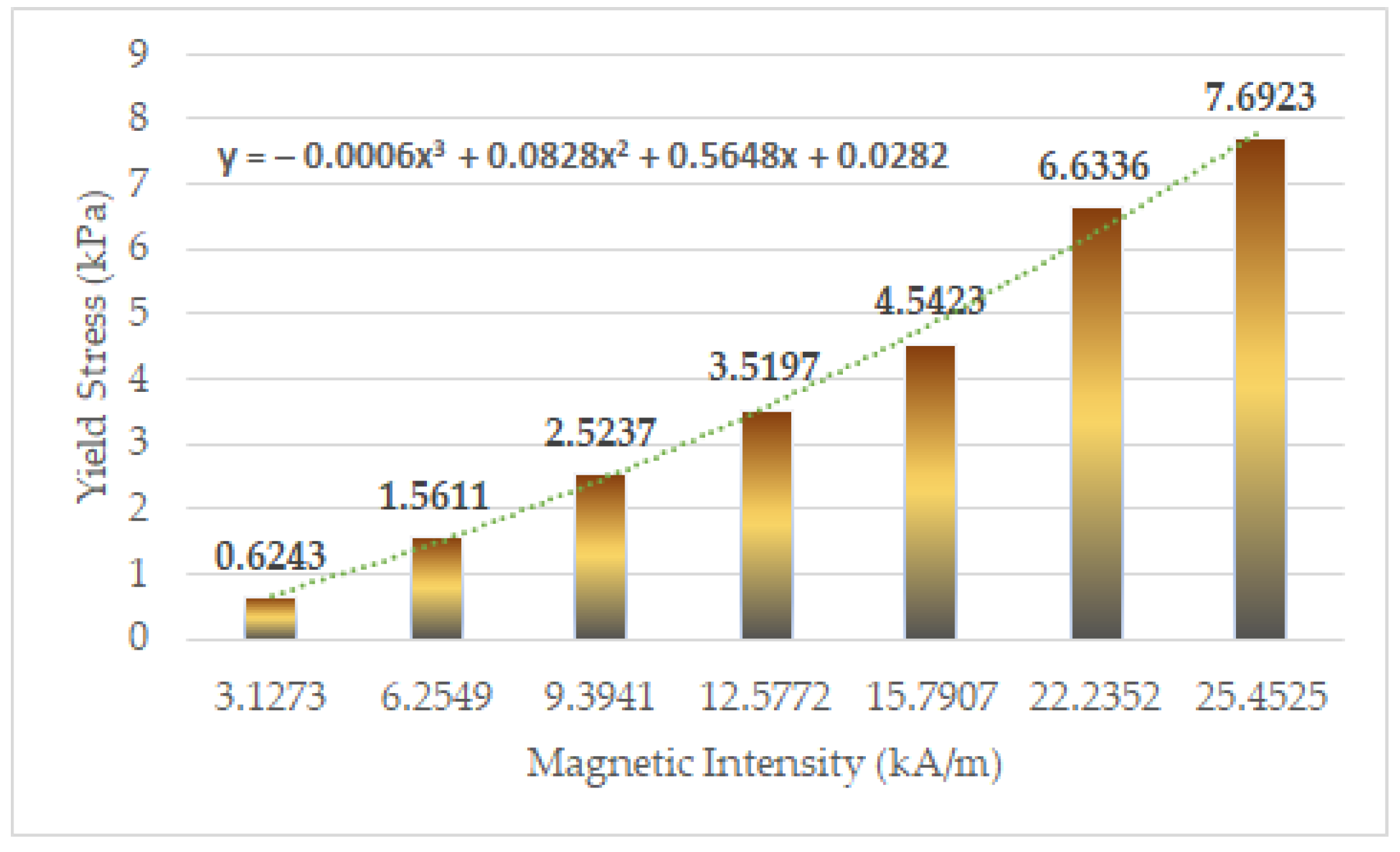
| Magnetic Field Strength (Input Value of Current) Unit: A | ||
|---|---|---|
| 0.05 | 3.1273 | 0.6243 |
| 0.1 | 6.2549 | 1.5611 |
| 0.15 | 9.3941 | 2.5237 |
| 0.2 | 12.5772 | 3.5197 |
| 0.25 | 15.7907 | 4.5423 |
| 0.3 | 22.2352 | 6.6336 |
| 0.35 | 25.4525 | 7.6923 |
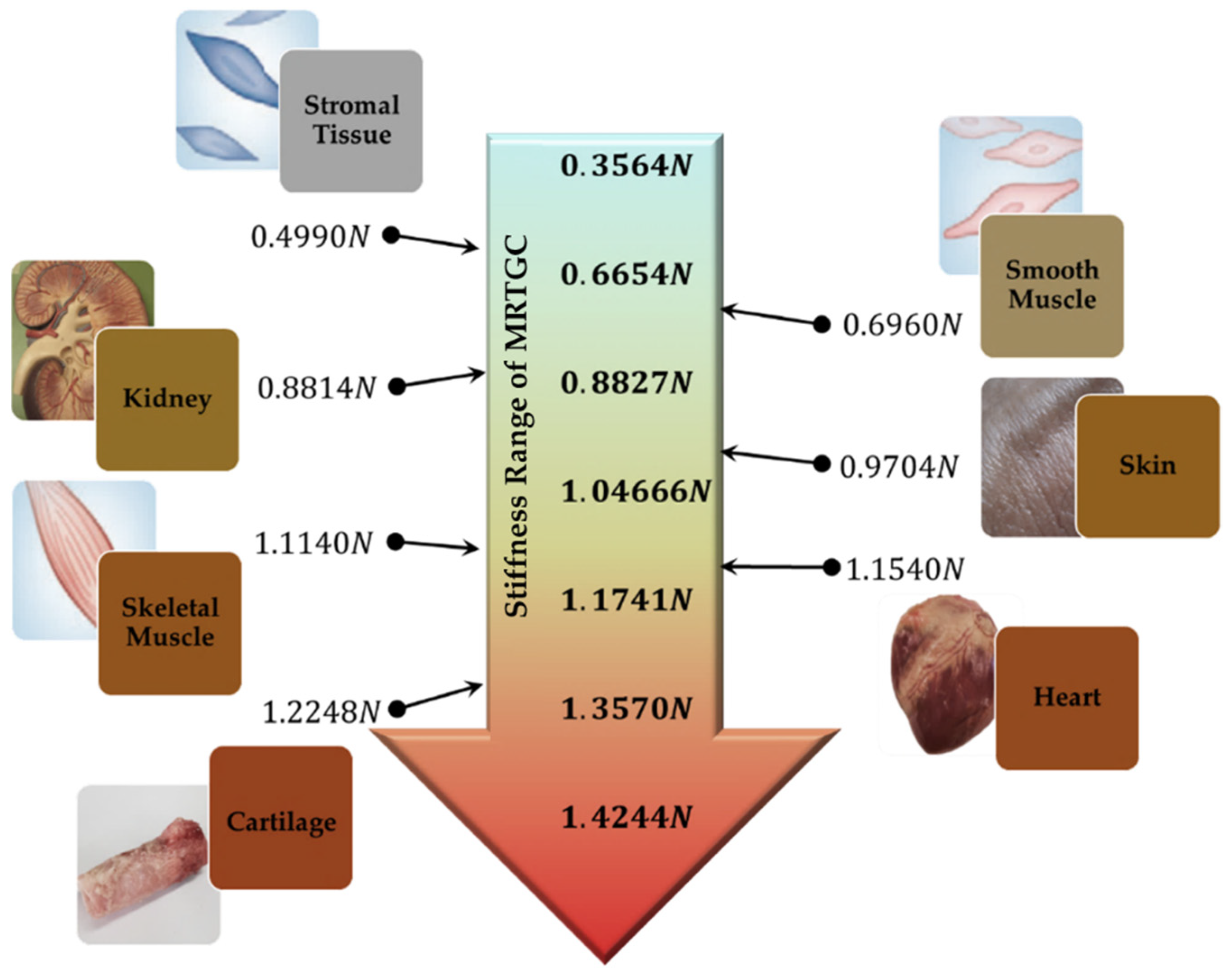
| Magnetic Field Strength (Input Value of Current) Unit: A | Stiffness (N) |
|---|---|
| 0.05 | 0.3564 |
| 0.1 | 0.6654 |
| 0.15 | 0.8827 |
| 0.2 | 1.0466 |
| 0.25 | 1.1741 |
| 0.3 | 1.3570 |
| 0.35 | 1.4244 |
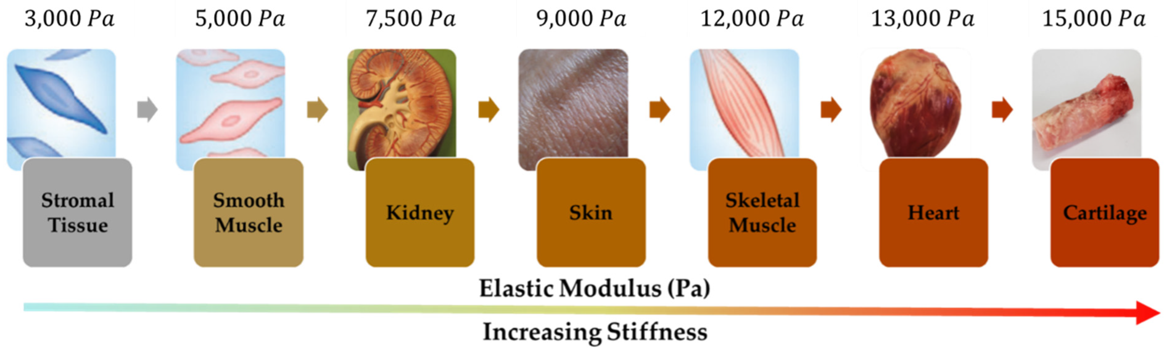
| Human Tissue | |
|---|---|
| Stromal Tissue | 0.4990 |
| Smooth Muscle | 0.6960 |
| Kidney | 0.8814 |
| Skin | 0.9704 |
| Skeletal Muscle | 1.1140 |
| Heart | 1.1540 |
| Cartilage | 1.2248 |
Publisher’s Note: MDPI stays neutral with regard to jurisdictional claims in published maps and institutional affiliations. |
© 2022 by the authors. Licensee MDPI, Basel, Switzerland. This article is an open access article distributed under the terms and conditions of the Creative Commons Attribution (CC BY) license (https://creativecommons.org/licenses/by/4.0/).
Share and Cite
Park, Y.-J.; Lee, E.-S.; Choi, S.-B. A Cylindrical Grip Type of Tactile Device Using Magneto-Responsive Materials Integrated with Surgical Robot Console: Design and Analysis. Sensors 2022, 22, 1085. https://doi.org/10.3390/s22031085
Park Y-J, Lee E-S, Choi S-B. A Cylindrical Grip Type of Tactile Device Using Magneto-Responsive Materials Integrated with Surgical Robot Console: Design and Analysis. Sensors. 2022; 22(3):1085. https://doi.org/10.3390/s22031085
Chicago/Turabian StylePark, Yu-Jin, Eun-Sang Lee, and Seung-Bok Choi. 2022. "A Cylindrical Grip Type of Tactile Device Using Magneto-Responsive Materials Integrated with Surgical Robot Console: Design and Analysis" Sensors 22, no. 3: 1085. https://doi.org/10.3390/s22031085
APA StylePark, Y.-J., Lee, E.-S., & Choi, S.-B. (2022). A Cylindrical Grip Type of Tactile Device Using Magneto-Responsive Materials Integrated with Surgical Robot Console: Design and Analysis. Sensors, 22(3), 1085. https://doi.org/10.3390/s22031085